ACKNOWLEDGEMEMTS
I would like to thank Dr. James E. Watson, Jr. for his personal interest and guidance during this study. I am also grateful to Dr. Douglas J. Crawford-Brown and Dr. Alvis G. Turner, Jr. for their positive criticism and support during the preparation of this report.
Support by Carolina Power & Light Company through part-time employment is especially appreciated.
ABSTRACT
David S. Lee. An Analysis of Hydrogen Gas Generation
Specific to Dewatered Ion Exchange Resins in
Radioactive Waste Shipment Containers. (Under the
direction of Dr. James E. Watson, Jr.)
The analysis of hydrogen gaa generation in
radioactive waste containers considers the following
areas: 1) the radiolytic reaction of water and
dewatered ion exchange resins, 2) the parameters
associated with the rate of hydrogen generation, and 3)
the evaluation of an equation, which determines the
rate of hydrogen generation, to aid in compliance with
regulatory requirements. The two primary factors needed
for the determination of the hydrogen gas generation
rate are the total absorbed energy and the hydrogen
generation constant, G(H2>- The method developed by
EG&G Idaho, Inc. adequately incorporates these two
factors. However, there is a degree of uncertainty
within this method. At present, the G<:H2> values in the
literature do not accurately represent typical resins
used in the industry. Variables which affect the G<H2>
have been identified. The degree to which these
TABLE OF CONTENTS
Page
I- INTRODUCTION 1
A) Purpose 1 Bi Radwaste Shipment Containers 1
C> Identification of Gas Generation Concerns 3
D> NRC Regulatory Implementation 4 E) Scope &
II. MECHANISM OF H2 GENERATION 9
A) The Radiolysis of H2O
B> The Radiolysis of Dewatered Ion 17
Exchange Resins
III. PARAMETERS ASSOCIATED WITH HYDROGEN 22
GENERATION
A) Total Absorbed Energy 22
B> G - value <H2) 23
i^aae
IV. EVALUATION OF A CALCULATIONAL TECHNIQUE FOR 26
DETERMINING THE RATE OF HYDROGEN GENERATION
A) Background 26 B> Equation 26 C) Parameter Considerations Within Equation 33 D) Application of Method 35
V. CONCLUSIONS 39
VI. RECOMMENDATIONS 40
REFERENCES
List of Fiqures
Pacje Figure 1. The formation of free radicals from low 13
and high LET tracks.
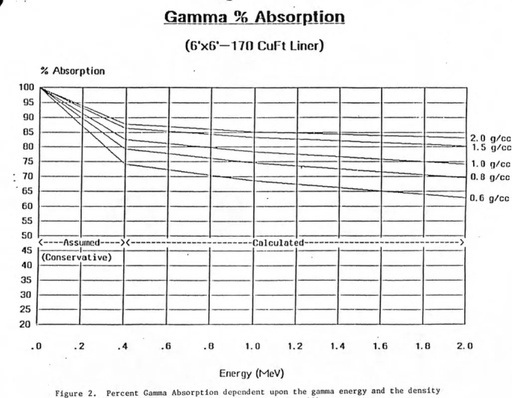
Figure 2. Percent gamma absorption dependent upon 31 the gamma energy and the density of the
absorbing media. (Taken from Flaherty, 11).
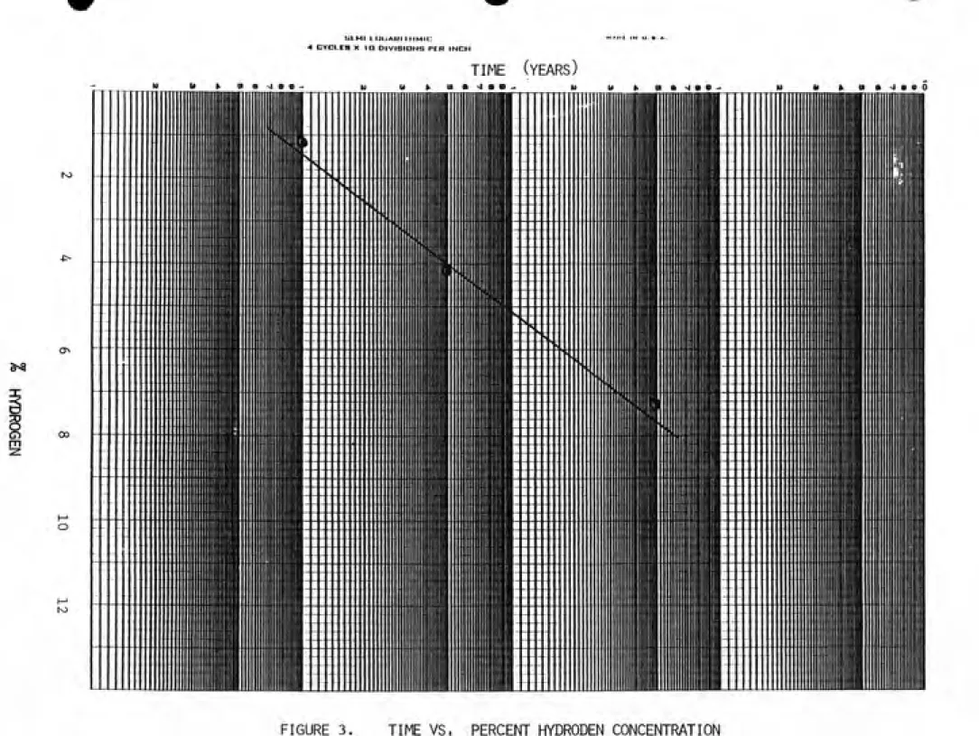
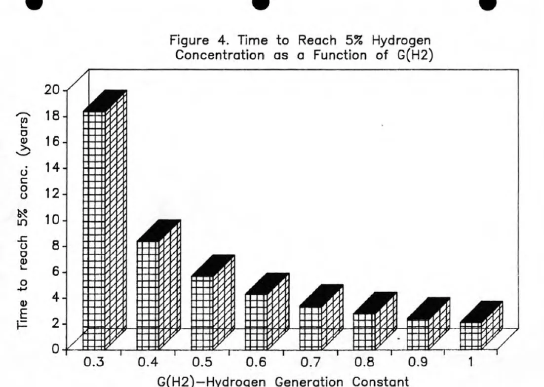
Figure 3. Time versus percent hydrogen concentration. 37 Figure 4. Time to reach 5% hydrogen concentration as 38
G(H2)-.ist of Tables
Page
Table 1. Hydrogen gas evolved from Dowex SOW 19
and Zeo-Karb 215. G(H2> = # molecules formed per 100 eV absorbed. (Taken from
Mohorcic, 23:) .
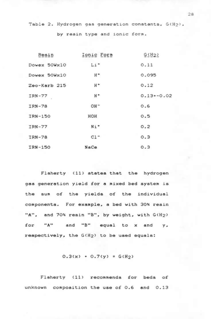
Table 2. Hydrogen gas generation constants, 28
G(H2'>» by resin type and ionic form.
I?:IIBQDycTigN
The purpose of this study is to gain further insight into the subject of hydrogen generation in radioactive waste containers. Specific areas of study are as follows: 1) the radiolytic reaction of water and dewatered ion exchange resina, 2) the parameters associated with the rate of hydrogen generation, and 3) the evaluation of an equation, which determines the rate of hydrogen generation, to aid in compliance with
regulatory requirements.
^' B§^y5§jfe® Shipment Containers
The activity and type of radionuclides present within waste material are determining factors for the selection, preparation, and transportation of waste containers for burial. For example, ion exchange resina
and filter media must be stabilized if they contain
isotopes with greater than five year half-lives with a
specific activity greater than or equal to one
microcurle per cubic centimeter. This stabilization may be of two forma; 1) solidified or 2) dewatered in
an approved high integrity container (HIC). A HIC la
designed to contain waste for approximately 300 years
approved shipping cask offers additional containment
and shielding for a HIC during transport to the
burial site. A Certificate of Compliance, which
accompanies each type of cask, is certification by the
NRC that a particular type of cask has undergone
requirements as described in 10 CFR 71 (7) and 49 CFR
173.471 <8). These requirements include such
performance 'tests for containment integrity under
extremely low and high temperature, external pressure
changes, vibration, water spray, free drop,
compression, and penetration. These tests represent
hypothetical accident conditions for each cask.
The majority of low-level radwaste does not
warrant high integrity containers or heavy duty
transport casks as described above. It is typically
transported and buried in metal drums or metal boxes.
Low-level radwaste in these containers may be further
classified aa dry active waste <DAW>. DAW is unprocessed by-product material which is free of all
free standing liquids. The mode of transport for DAW
is usually a flatbed trailer for boxes and a closed van
for drums.
Regulations governing the packaging, transport,
and burial of radwaste are extensive. They are designed
C) Identification of Gas Generation Concerns
The concern for hydrogen gas generation is a result of the detection of hydrogen gas in Eplcor II liners used during the cleanup of contaminated water at
Three Mile Island Unit 2. The waste within these liners contained much more activity than typical plant waste (Flaherty, 11). It was expected, with the radiolytic reaction in mind, that the activity would produce a hydrogen gas concentration that could possibly exceed the internal pressure capabilities of the liner. Although none of the liners erupted, hydrogen gas was detected by use of a gas chromatograph. The studies resulting from the sampling, preparation and shipping of these liners represent the only field data obtained from actual plant waste.
Organic ion exchange resins are used throughout the industry within the normal operations of a nuclear plant radwaate system. Resins function to control the purity of such liquid streams as the primary coolant, water in the spent fuel storage pools, and liquid radwaste resulting from normal plant operations- The resins filter radioactive ionic species and particulate matter from the various liquid streams. After maximum
usage the resin is packaged in liners and transported
4
Hydrogen generation within imers containing
organic ion exchange resins is the result of two
processes. The first is the decomposition of the resin and the second is the radiolytic reaction within the resin/water media.
After considering these facts and reviewing technical studies by MacKenzie <21) and Barletta et, al. (3), the NRC determined that the issue of hydrogen generation in waste containers must be addressed.
EG&G Idaho is presently working on a calculational technique to predict the rate of hydrogen generation in sealed radioactive waate containers. The generation rates calculated from this technique are being compared to data obtained from the processing of the Epicor II liners at Three Mile Island < Flaherty, 11).
The Nuclear Regulatory Commission has imposed changes within the Certificates of Compliance for certain waate ahipping caaka (NRC IE Information Notice
No. 84-72, 33). These conditions pertain to those
radioactive waste packages which may accumulate
radiolytically generated gases over the shipping
period. The conditions atem from preexisting regulatory
requirements in 10 CFR 61.56 (6) with the intent to
preclude the possibility of explosion which would
5
conditions imposed may be divided into two categories:
1> teats and measurements and 23 shipping within ten
days of preparation or within ten days after venting.
The NRC IE Information Notice No. 84-72 (333 states the
conditions as follows:
<1) For any package containing water and/or organic substances which could radiolytically generate combustible gases, determination must be made by tests and measurements or by analysis (sic calculational method) of a representative package such that the following criteria are met over a period of time that is twice the expected shipment
time:
(a) The hydrogen generated must be limited to a molar quantity that would be no more than S?* by volume (or equivalent limits for other inflammable gases) of the secondary container gas void, if present, at STP <ie., no more
than 0.063 g-moles/ft3 at 14.7 psia and 70OF)
or
<b) The secondary container and cask cavity
must be inerted with a diluent to ensure that
oxygen must be limited to 5X by volume in those portions of the package that could have
ͣ
ajg^ai^.iR~
For any package delivered to a carrier for transport, the secondary container must be prepared for shipment in the same manner in which determination for gas generation is made. The shipment period begins when the package is prepared (sealed) and must be completed within twice the expected shipment
time. '3
<2) For any package containing materials
with radioactivity concentration not exceeding that for low specific activity <LSA) material, and shipped within 10 days of preparation, or within 10 days after venting of drums or other secondary containers, the determination in <1) above need not be made, and the time
restriction in (1) above does not apply.
Compliance by tests and measurements as described in section (1) above, would result in expensive container modifications for a sampling port or an expensive inerting program. Compliance, as described in section <2> above, is the best solution, if the package is shipped within 10 days of preparation. However, long-term on-site storage may soon be the norm with the implementation of the Low-Level Radioactive Waste
Policy Act of 1980. This act provides for the formation of interstate regional disposal facilities (compacts:' to relieve the present burden of the three states with LLW disposal sites. After January 1, 1986 states with regional waste compacts will not accept LLW from nonmember states, thus requiring on-aite storage for the affected utilities. Therefore, storing the containers, returning to vent, and then shipping withm 10 days results in increased exposure to personnel. The practice of temporary on-site storage further enhances the problems associated with following good ALARA practices while maintaining assurance that the rate of hydrogen generation and other combustible mixtures is below explosive levels. Mechanical means of sampling and inerting yields excess disposal costs, while venting the containers periodically yields excess
exposure to personnel.
An alternate approach is to utilize a calculational method which accurately determines the rate of hydrogen gas generation. This approach would be a type of analysis and would fulfill the criteria as stated in section (1) above. Exposure to personnel during tests and measurements would be eliminated and the frequency of container venting, while being stored
E) 599P^
Within the scope of this study are the following
objectives:
"" To describe the radiolytic reaction of dewatered ion exchange resins by means of a literature
review.
'~ To describe parameters which influence the rate of hydrogen generation. The literature review
will identify these parameters.
'ͣ To evaluate an equation which determines the rate of hydrogen generation. This evaluation will
MiQHANISM OF HYDROGEN GENERATION
The radiolysis of water is the chemical
decomposition of water molecules by the action of radiation. Orekhov et. al. (27) report that according to approximate calculations the number of radiolyzed water molecules reaches a value of 10 to 12 per 100 eV during the passage of ionizing particles through water.
This number includes both ionized and excited water
molecules. The ionization of water molecules, accounting for about half of the absorbed energy, leads to the formation of chemically active products of a radical character <HO and OHO). Subsequent recombinations between the H° and 0H° radicals produce hydrogen <H2>» hydrogen peroxide <H2025, and water <H20). Carswell <5), in a simplified form, presents the following reactions for the production of the
radical and molecular products:
H2O---> H -ͣ OH
2H---> H2
20H---> H2O2
Those molecules raised to an excited state may possess electrons raised to different levels depending upon the amount of energy absorbed- As these molecules return to the ground state energy will be released. However, the contribution of excited molecules to the radiolysis of water and aqueous solutions is generally insignificant
(Denaro, 10).
The photoelectric effect and Compton scatter are the two photon interactions considered concerning the radiolysis of water. The probability of pair production, per gram of absorber, is directly proportional to the atomic number <Z) (Gollnick,13). Therefore, hydrogen with an atomic number of one and oxygen with an atomic number of eight are not expected to have substantial interactions via the pair
production process.
A full energy transfer to an inner shell electron ia the result of photon interaction by the photoelectric effect. The photoelectric interaction ia directly proportional to the cube of the atomic
number, Z, and inversely proportional to the cube of
the energy of the photon.A Compton scatter interaction results in a recoil
energy of the incident photon, but is independent of the atomic number of the absorber.
The resulting ionizations from those ejected
electrons from photon interactions are termed "indirect" ionizations. Those ionizations resulting from a particle emission are termed "direct" ionizations. Subsequent indirect and direct ionizations depend upon both the probability of the interaction and the amount of energy transferred from each event. As each ionization occurs, the energy of a moving electron is decreasing. Since the probability of an event increases the longer the electron remains in the presence of the water molecule, more events will occur as the moving electron decreases in velocity. Since secondary electrons have less energy than the primary electrons, the probability of an event along the secondary electron track will be greater than the probability of an event along the primary electron track.
Similar to this concept is the parameter, linear energy transfer (LET). As defined by Lapp and Andrews
<18), LET is represented by the equation:
dE LET
dX
12
imparted to the medium at or near the site of the
track.
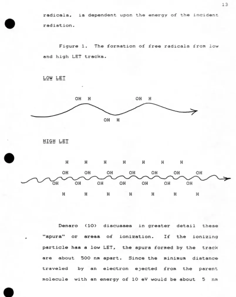
Areas of ionization are produced as energy is transfered along this track. In water the free radicals H° and 0H° will be formed as a result of these ionizations. The concentration of these ionized areas will differ between low and high LET tracks. Therefore, the irradiation of water molecules producing the free radicals H° and 0H° will yield differing radical concentrations for differing LET radiations.
The ionization of water molecules leads to the
formation of the molecular products H2 (hydrogen) and H2O2 (hydrogen peroxide). These molecular products are formed by the recombination of the radicals H° and 0H°, produced along the particle track. The differing radical concentrations will yield different radical recombination probabilities. The higher the concentration the higher the probability of recombination. Therefore, low and high LET tracks vary in the probabilities for radical recombination. An example of these two types of tracks is illustrated in
Figure 1.
?^^i0K''"^i^?^'
13
radicals, is dependent upon the energy of the incident
radiation.
Figure 1. The formation of free radicals ±"rom low
and high LET tracks.
LOW LET
OH H OH H
OH H
HIGH LET
H H H H H H H
OH OH OH OH OH OH OH
OH OH OH OH OH OH OH
H H H H H H H
14
before thermalization, it will still be within the spur. If the ionizing particle has a high LET, the spurs themselves are only about 1 nm apart and therefore overlap from the moment of formation. This produces a columnar track with a high concentration of
radicals.
With the spurs being isolated with low LET radiation, the radicals may diffuse so that radical concentration decreases quite rapidly. After diffusion
the radicals are available to react with materials in
the solution. Since H is a strong reducing agent and OH a strong oxidizing agent, oxidation - reduction
reactions are common in irradiated solutions (Allen et.
al., 1>. It is expected in this situation that the amount of H2 and H2O2 formed along the track will be small versus the number of radicals escaping into the
solution or recombining to form water.
High LET radiation forms overlaping spurs in the form of a densely packed columnar track. In this situation, many radicals recombine with each other with only a few escaping into the solution. A slow moving heavy particle will have a relatively straight track, remaining in the presence of water molecules for a relatively long period. This increases the probability
of an event and forma a concentrated columnar track o£
recombination probabilities producing the molecular
products H2» H202» and H2O (Carawell, 5). Therefore, with high LET radiation, greater quantities o£ H2. ^2^2' and H2O would be expected to form than in the cas,& o£ low LET radiation Cfor the same total energy
deposited per unit mass).
Another factor within this scope of recombination
properties is the influence of radical scavengers. These scavengers bond with radicals, preventing their reaction with other products. Iodine, oxygen, palladium, and bromide are several examples of radical
scavengers (Denaro, 103. Experimentally, scavengers may be introduced to reduce the large number of species formed in some reactions. Extraction of these species
allows a more accurate measurement of a desired
reaction (Carswell, 5).
The presence of bromide ions, which are readily oxidized, is a good example of radical scavengers. Allen et. al. (1) give the following probable reactions
occuring with bromide ions:
Br- + OH --> Br ^ OH" Br + H --> H* -^
Br-H* - OH- --> H2O
Here the bromide ions act as catalysts for the
16
The final molecular yield o£ H2 is denoted by a G-value. The G-value for hydrogen, G(H2>» is the number of hydrogen molecules formed per 100 eV absorbed. Several factors affecting this yield are water purity, temperature, and LET of the incident radiation
(Martin, 20).
Allen et. al. (1) state that an increase in the
amount of water decomposition occured with an increase in added impurities. Since photons ionize Indirectly, added impurities with a density greater than that of water will increase the probability of secondary
ionizations. These additional ionizations will increase
the total amount of energy deposited. Therefore, if water decomposition depends upon the energy deposited (via the radiolysis of water) added impurities will increase the probability of water decomposition.
With decreasing temperature, the quantity of water decomposed decreases (Martin, 20). At lower temperatures, close to freezing, the dissipation of radicals formed is restricted by ice molecules. Therefore, recombination of radicals will occur with higher probability. This recombination will increase the yield of water molecules, while decreasing the yield of hydrogen gas or hydrogen peroxide molecules.
17
energy- Foremost in variation of the absorbed energy is the type of emissions incident upon the absorbing
media. The entirety of the emission energy is assumed
to be absorbed in the media for alpha and beta emissions, while absorption for gamma emissions may be from zero to one hundred percent, depending on the absorption coefficient and the geometrical dimensions of the media'. After ionization of the water molecule, direct for alpha and beta and indirect for gamma, the
LET affects the recombination probabilities of the radicals formed. High LET radiation produces a higher concentration of radicals. A higher concentration of radicals produces an increased probability for recombination, yielding higher G-values for the
molecular products formed.
The exact mechanisms to explain the interaction of radiation with different types of organic ion exchange resins have not been determined due to the complexity of the polymer systems (Gangwer, 12). However, the
kinds of chemical bonds attacked and the relative
degrees to which different types of chemical reactions
occur are known (MacKenzie, 21).
18
are: the C-C bonds in the polymer structural framework. the bonds linking the functional groups to the carbon framework, and the C-H bonds (MacKenzie, 21). Breaking of C-H bonds leads to the formation of hydrogen gas and to a certain amount of cross linking. The hydrogen gas is formed by the recombination of two H atoms, freed by the breaking of the C-H bond. MacKenzie (21) states that this cross linking is constructive rather than destructive, which may mitigate to some extent the damage done by other processes. However, the overall effect of radiation is deterioration of the resin, particularly in the presence of water and air. McFarland (22) irradiated cation and anion exchangers to high doses in an experiment where buildup of gas pressure was followed. The sum of the G-values
calculated for several gases , at 7.9 x 10® rad, were
0.09 and 0.69 for cation and anion exchangers, respectively (MacKenzie, 21). Of these G-values, G(H2> represented 4lx for cation exchangers and 53J« for anion exchangers. These data show that the anion exchanger exhibits a rate of gas production eight times that of the cation exchanger. MacKenzie (21) reports that in terns of total pressure a threshold for gas production exists around 5 x 10 ^rad.
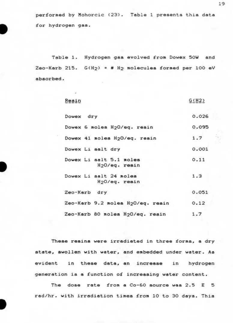
19 performed by Mohorcic (23). Table 1 presents this data
for hydrogen gas.
Table 1. Hydrogen gas evolved from Dowex SOW and Zeo-Karb 215. G<H2> = # H2 molecules formed per 100 eV
absorbed.
Resin G_(H2)
Dowex dry 0.026 Dowex 6 moles H20/eq. resin 0.095
Dowex 41 moles H20/eq. resin 1.7
Dowex Li salt dry O.OOl
Dowex Li salt 5.1 moles 0.11
H20/eq. resin
Dowex Li salt 24 moles 1.3
H20>'eq. resin
Zeo-Karb dry 0.051 Zeo-Karb 9.2 moles H20/eq. resin 0.12 Zeo-Karb 80 moles H20/eq. resin 1.7
These resins were irradiated in three forms, a dry state, swollen with water, and embedded under water. As evident in these data, an increase in hydrogen generation is a function of increasing water content.
The dose rate from a Co-60 source was 2.5 E 5
20
represents a dose range from 6 E 7 rad to 1.8 E S rad.
MacKenzie (21) reports the properties and the differences in susceptibility (these are generalizations with expected exceptions) of different types of resins with respect to degradation and
hydrogen gas production as follows:
- Most cation exchangers begin to show significant damage at a dose of around IE S rad, while most anion exchangers are damaged noticeably at a somewhat lower dose.
- A greater increase in resin degradation is
observed when resins are irradiated in the presence
of water than when they are irradiated dry.
- Results of investigations reported in the
literature support a nearly linear increase in gas generation with dose. McFarland (22) found an apparent threshold for gas production from
both cation and anion resin of about 5 E 7 rad.
- In general, generation of gases is
greater from anion than from cation resins. Of these gases, hydrogen seems always ro be
formed in the largest amount. Some of this
hydrogen is a result of radiolysis of water in
the resin matrix in moist resins, but in dry
resins it obviously must come from the resin
ͣ
'T'J^'VS^S?
EARAMETERS ASSOCIATED WITH HYDROGEN GENERATION
A^ X9tal Absorbed Energy
Factors determining the total absorbed energy
within the resin/water media are as follows: 1)
radionuclide composition, 2> density of absorbing
media, and 3> container geometry.
The radionuclides present within the media are determinants as to the type of radiation and quantity of energy incident upon the media. Particle emissions below a particular energy may be absorbed 100?s except in the exterior layer of media. The depth of this layer will depend upon the range of the particlein the media. Those particles with a range greater than their depth
of emission from the nearest surface of the container
will not transfer their total energy- The percent of photon absorption will depend upon the energy of the photon and the mass absorption coefficient o£ the
media. ,
23
The more dense the media the greater the probability
for an event. Most events will either be a
photoelectric or a Compton scatter event. The energy of the photon and the atomic number of the absorber affect
the probability for each of these events.
Assuming a uniform distribution of nuclides within
the waste media, the geometry of the container &££s:at.s. the energy absorbed by the media. For example, waste in a spherical container will have a higher percentage of self-absorption than an equal volume of waste in a long, flat container. Although these geometries are hypothetical they demonstrate the effect of container
geometry upon absorbed energy.
Two factors which affect the G<H2> are; 1) the LET of the incident radiation, and 2) the specific
characteristics of the waste media.
Aa described previously, the LET dependence of G(H2> is established by the variation of net hydrogen formation between low and high LET radiations. High LET radiation produces greater quantities of hydrogen gas than low LET radiation.
Specific characteristics of the waste media which
affect G<H2> are; the percent water content, the type
of resin, the impurities within the media, the presence
24
hydrogen
peroxide-The two mechanisms for hydrogen gas production in dewatered ion exchange resins are the radiolysis of
water and reain degradation. Of the two, the radiolysis
of water is the predominant mechanism. Therefore the
percent water content within the waate media ia an important variable in the production of hydrogen gas (Refer to Table 1).
Differing reain types, whether anion, cation or
manufactures' brands, yield different values of G<H2>• Gaa generation ia generally greater from anion than from cation resina. If the polymer structural framework
differs between different manufactures' reaina, the
hydrogen generation values may differ also.
Added impuritiea within the waate media will
increase the number of available "targets" for an ionizing event. lonizationa produce those radicals which later recombine to form hydrogen gas. Therefore,
with an increase in the probability of an ionizing event cornea an increase in the probability of radical formation. The probability of radical recombination for
particular molecular formation ia dependent upon the
LET of the incident radiation and the radical
acavengers present within the media.
Radical scavengers bond to radicals preventing
them from reacting with other products. The presence of
25 affect the formation of the molecular products H2r
H2O2 and H2O.
The chemical interaction of hydrogen peroxide with
the resin will cause some C-H bonds to break, thus
A^ §52i53?!9yDd
The Utility Nuclear Waste Management Group (UNWMG) of the Edison Electric Institute formed a "Hydrogen Generation Task Force" to evaluate those requirements
stated in the NRC IE Information Notice No. 84-72. The
Task Force requested technical assistance from EG&G Idaho, Inc. Aa a result, EG&G developed a calculational method to quantify hydrogen gas generation in sealed
containers (Flaherty, 11).
B)Eguation
The following is the method presented by Flaherty (11) to determine the time to reach a hydrogen gas concentration equal to 5?< of the free volume within a container:
Step 1) Determine the absorbed dose necessary to generate a 5S£ hydrogen gas concentration
27
(.05>FV
D5 (5?< H2 cone.) = --- <Eq. 1)
<GC)(m)<K)
where: FV = free volume of the container (cc'>
GC = G<H2) H2 generation constant
(molecules/'lOO eV absorbed)
m = mass of waste (grams)
K = 2.33 X 10-S eV-gc
rad-gm-molecule
The free volume (FV) of the container is
the container volume minus the waste volume
plus the interstitial free volume. The
interstitial free volume is the interstitial
void space ratio times the waste volume. The interstitial void space ratio is the difference between the true and bulk denaity divided by the true density of the resin. The true and bulk density may be obtained from the resin manufacturer.
Flaherty (11) reports from the literature G(H2) for the several types of resins. These
2S
Table 2. Hydrogen gas generation constants, G<H2'f
by resin type and ionic form.
G<H22
0.11
0.095
0.12
0.13-^-0.02 0.6
0.5 0.2 0.3
0.3
Resin Ionic Form
Dowex SOWxlO Li-^
Dowex SOWxlO H*
Zeo-Karb 215
H*-IRN-77 H*
IRN-78
OH-IRN-150 HOH
IRN-77 Ni*
IRN-78
ci-IRN-150 NaCe
Flaherty (11) states that the hydrogen
gas generation yield for a mixed bed system is
the sum of the yields of the individual components- For example, a bed with 305< resin
"A", and 70?i resin "B", by weight, with G<H2>
for "A" and "B" equal to x and y, respectively, the G<H2) to be used equals:
0.3<x) * 0.7<y) = G<H2)
29
for the G(H25 values for anion and cation reams,
respectively, and for solidified resin/cement the use
of a value of 0.24. The constant <K> is derived aa
follows:
K = (22.4 l/mole> ClOOO cc/1) (lOO ergs/gm-rad)
<eV/l.6xlO~12 ergs) divided by 6.02xlo23 molecules/mole
This gives a value of 2.33x10"^
eV-cc/rad-gm-molecule. Since the G<H25 is defined aa #
moleculeaylOO eV absorbed and that value is
reported as that integer (for example, a
value of 0.3 moleculea/lOO eV absorbed ia
reported aa 0.3) the incorporation of thia
factor of 100 produces the value of 2.33xlO~S
eV-cc/rad-gm-molecule.
Step 2a) Determine the absorbed dose for each
radionuclide at time intervals (at leaat
three) using the following equation:
D<n,t) =l3>AlEbetaliSanima>liz§---2 <Eq- 2) h
where: D(n,t) = dose from nuclide, n, at time, t. a = specific activity (Ci/gm)
A = 1.86x10¹⁰ rad-gm
30
Ebeta ~ average beta energy (MeV/dis)
Egamma " (gamma energy)<^ abundance)
X <5« gamma absorption) See Figure 2. (MeV/dis)
h = radiological decay constant (yrs."-*-)
t = time (years)
The specific activity (a) may be recorded
from data obtained by normal plant
procedures-The constant (A) is derived as follows:
<3.7xl0l0 dis/s/Ci>(1.6x10-6 ergs/WeV) <1 rad-gm/100 ergs) (3.15x10*7 s/yr)
The average beta energy for each nuclide,
it's decay constant, and it's gamma energy and
abundance, are easily obtainable from numerous
tables (eg. in radiological handbooks).
The gamma energy absorption la the
fraction taken from Figure 2. The fraction of
gamma energy absorbed was calculated by
evaluating the energy received at up to 200
detector sub-volumes as a result of
irradiation by a maximum of one million source
sub-volumes. The total absorbed gamma energy
% Absorption
100
95 90 05 00
75
70
ͣ
65
60
55
50 45 40 35 30
25
20
Gamma % Absorption
(6"x6'-17nCuFt Liner)
<---Assumed---><---Calculated
2.0 g/cc 1. 5 g/cc 1.0 rj/cc 0.0 g/cc
0.6 g/cc
—---1---(Conservative)
'.0
.6 .0
1.0 1.2
1.4 1.6
1.0 2.0
Energy (MeV)
32 photon, the density of the absorbing media and
the volume and geometry of the absorbing
media. Similar figures, yielding the gamma energy absorbed fraction, have been calculated by EG&G, Idaho, Inc., for other
volumes/geometries <eg. 98 ft^/S'in height by
5'in diameter).Step 2b) Determine the total absorbed dose, Dt- Dt is the sum of the doses contributed by
radionuclides, n at time, t.
Dt = 4E D<n,t) <Eq. 3)
n
Step 3) Determine the percent hydrogen concentration for each time interval using the
following equation:
'«H2 at timeft) = iUtli^li^Q:li\ill99. <E<3- "*)
FV
where: Dt = total absorbed dose <Eq. 3)
Using Eq. 1; '«H2 at time, t <Eq. 4), becomes
33
Step 4) Determine the time to reach a 5^4 hydrogen concentration by one of two methods;
A) Plot on semi-log paper the values
determined in Eq. 4 < ^shydrogen versus time> . B) Use a computer to iterate Eq. 2 for
each radionuclide for values of time, t, until
the total absorbed dose, Dt equals the dose,
D5 determined in Eq. 1.
C) Parameter Considerations Within Eguation
The formulation of the method presented by Flaherty (11) is correct. He considers the three factors affecting the total absorbed energy, previously discussed. They are the radionuclide composition, the density of the absorbing media and the container
geometry.
However, the use of an inaccurate G(H2> would produce an incorrect value for, 1) the dose necessary to reach a 5J« hydrogen concentration (Eq. 1), and 2) the %5 hydrogen at time, t (Eq. 5). Because of this there is an uncertainty associated with the
calculational method.
34
were from on© hour to thirty days. The ampules were
immediately sampled for hydrogen gas after the
irradiation period. The amount of H2 was then converted
to a G-value with units of the number of H2 molecules
per 100 eV
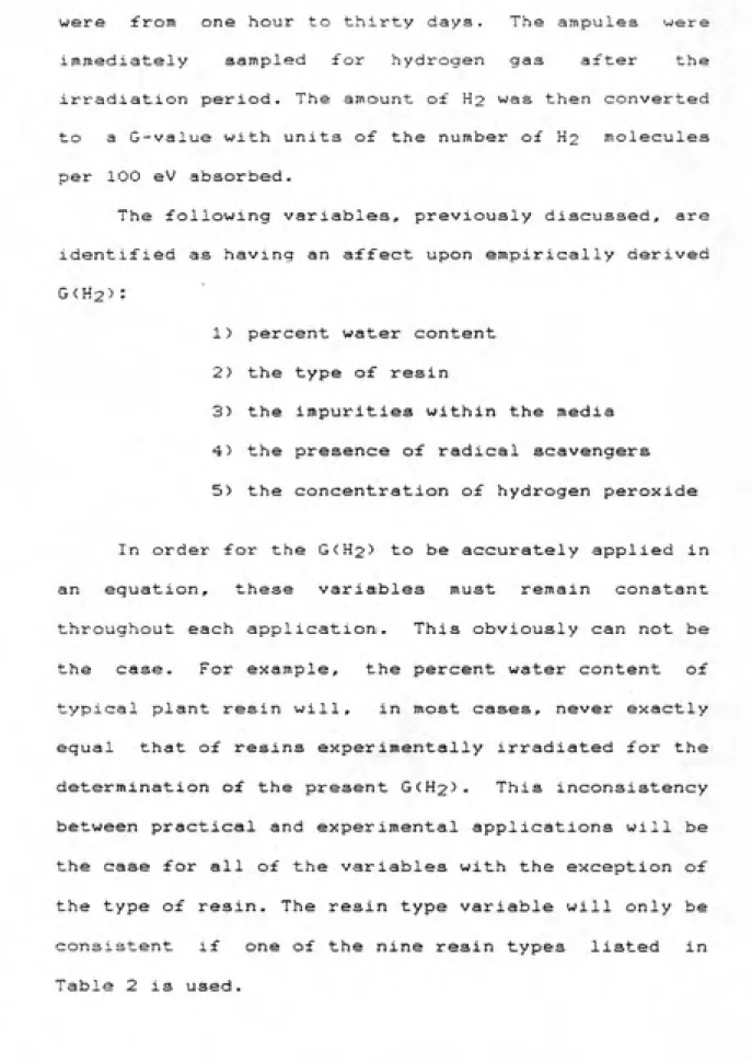
absorbed-The following variables, previously discussed, are
identified as having an affect upon empirically derived
G(H25:
1) percent water content
2> the type of resin
3) the impurities within the media
4) the presence of radical scavengers 5) the concentration of hydrogen peroxide
In order for the G<H2) to be accurately applied in
an equation, these variables must remain constant throughout each application. This obviously can not be the case. For example, the percent water content of
typical plant resin will, in most cases, never exactly
equal that o£ resins experimentally irradiated for the determination of the present G<H25- This inconsistency between practical and experimental applications will be the case for all of the variables with the exception of the type of resin. The resin type variable will only be consistent if one of the nine resin types listed in
35
A computer program has been developed for the
utilization o£ step 4(B). Step 4CB) necessitates the
use of a computer to iterate Eq- 2 for each
radionuclide for values of time, t, until the total
absorbed dose, Dt equals the dose, D5 determined in
Eq-1. The program incorporates all of the steps necessary
for the completion of the method. The program is
included as Attachment A.
Sample data were entered into the program as
follows:
container volume 5.52 E 6 cc
waste volume 4.81 E 6 cc
bulk density 0.19 g/cc
true density 1.12 g/cc
mass of waste 9.25 E 5 g
G(H2) 0.4
radionucliderspecific activity C06O: 1.5 E -4 Ci/g
Csl37: 2.6 E -6 Ci/g
Mn54: 1.7 E -4 Ci/g
<note: These data were obtained from a radioactive
waste shipment from a BWR)
The computer program gives the time to reach the
specified hydrogen concentration (5% of the free
36
this concentration (D5) equals 2.72 E 7 rads.
Input of the sample data into step 4(A) yields the
following:
Eq, 1 D5 = 2,64 E 7 rad
Eq. 2 Nuclide
1
li me <years)^
5 15
C06O 4.9 E 6 1.9 E 7 3-4 E 7
Cal37 2.9 E 4 1.4 E 5 3.7 E 5
Mn54 1.3 E 6 2.2 E 6 2.3 E 6
Dt Total 6.2E6 2.1E7 3.7E7
Using Eq. 5; % Hydrogen at: 1 year =1.2
5 years =4.1
15 years = 7.1
These data, plotted as Figure 3, reveal that the time to reach a 55« hydrogen concentration is equal to
approximately 9 years.
In order to evaluate how a range of G<H2> values affect the method, differing values were used with all
other variables remaining constant. The results are
MMI tlJUARt MIMIi:
4 CVOtCS K lO OIVHWONB PCR INCH M*»K IN W. ».«.
TIME (years)
N>
3>«
m
00
ls>
Figure 4. Time to Reach 5% Hydrogen
Concentration as a Function of G(H2)
(0
o
O
c
o
o
in
x: o D
Q)
E
;^
m^
f
w
0.4 0.5 0.6 0.7 0.8 0.9
CONCLUSIONS
The calculational technique developed by EG&G Idaho, Inc. has the potential to provide an adequate analysis of the hydrogen gas concentration in waste
containers. It's accuracy is questionable because of
the use of what may be non-representative G<H2> values. It has been determined in this report that several
variables affect these values. At present, data are not
available to determine the extent to which these
variables alter the G(H25.
Considering the very small molecular size of hydrogen gas, diffusion from a sealed container is far from improbable. Diffusion may occur through the container walls or through very small molecular spaces existing within a sealant media. A sealant media typically is used between removable lids and may be in the form of a gel or rubber stripping. MacKenzie (21> supports this theory and goes further to state that it would constitute a mitigating effect in the case of a limiting dose to be set on the basis of gas generation. At present, studies for the determination of the rate of diffussion for specific containers have not been
BECOMMENDATIONS
It is recommended that more studies be performed
to accurately determine G<H2>- A study design for the
determination of G<H25 values should include the
the following steps;
A> determine the free volume within the
experimental container.
B) determine the hydrogen gas diffuaic^n rate of the
container.
C) determine the radionuclide concentration,
density of the media, and geometry of the
container, yielding the energy absorbed in the
waste media. Quantify/address the following
variables for the;
A) Energy absorbed
1) LET of radiation B) Waste media
1) water content
2) resin type
3) impurities within the media
4) prescence of radical scavengers
5) concentration of hydrogen peroxide
41
E) determine the sensitivity and efficiency of the instrument (eg. mass spectrometer> to measure
the hydrogen gas concentration.
F) determine the number of hydrogen gas molecules
from the concentration of hydrogen gas <Step D>. G> determine the G(H2> value (number of hydrogen molecules formed per 100 eV absorbed) by
dividing the number of hydrogen molecules (Step
F> by the energy absorbed (Step C>.
It is also recommended that H2 gas diffusaion rates for specific containers be studied.
The above mentioned studies may determine that the G(H2> presently in the literature do not accurately represent resins used in the industry. However, until this is shown, the present values should be used in the
calculational method.
The determination of the most appropriate G(H2> for a resin type should consider the form of stabilization, either solidified in cement or dewatered. If solidified in cement, Flaherty recommends a G(H2> value of 0.24. If the resin is dewatered, the
type of resin must be considered. If a G<H2> has not
been measured for a particular type, the G(H2> of the type most similar in physical and chemical composition,
REFERENCE LIS1
<1) Allen, A. O., J. A. Hochanadel, J. A. Ghormley, and T. W. Davis, " Decomposition of Water and
Aqueous Solutions Under Mixed Fast Neutron and Gamma Radiation. " J. Phys. CHEM. 56. p. 575. 195:
(2) Allen, A. 0-,The Radiation Chemistrj^ of Water and Agueous SolytionSj^ D. Van Nostrad Co., Inc. New
York, NY. 404 p. 1961,
(3) Barletta, R.E., K.J- Swyler, S.F. Chan, and R.E. Davis., "Solidification of Irradiated Epicor-II Waste Products". NUREG/CR-2969, BNL-NUREG-51590. May, 1983.
<4) Bibler, N. E., R. M. Wallace, and M. A. Ebra, §^i[§9t§ 9^ iiigb B5^i§ti9D 52§?§ 9D LiDg? l9D §iy Iir§5, E. I. duPont de Nemours and Co., Savannah River Laboratory, Aiken, SC 29803.
DP-MS-81-1S.
(5) Carswell, D. J. iDtroductign to Nuclear CheinistrY Elsevier Publishing Co., NC. 279pp. 1967.
<6) Code of Federal Regulations, Title 10, Part 61.56.
(7) Code of Federal Regulations, Title 10, Part 71.
(8) Code of Federal Regulations, Title 49, Part 173.41
(9) Columbo, P., and R. M. Nielson, Jr., Brookhaven National Laboratory, " Properties of Radioactive Wastes and Containers, First Topical Report^" NSNRC Report, BNL-NUREG 50957, August, 1979.
(10"> Denaro, A. R., and G. G. Jayson. Fundamentals of B§yi5ti9D Qhemistrj^. Cox and Wyman. London,
•
(11) Flaherty, J. E., and J. R. Saunders.. "Hydrogen Gas
Generation and Determining the Sa£e Storage
Shipping Periods for Wet Organic Waste
Containers." Draft. EG&G Idaho, Inc. July. 1985.
<12) Gangwer, T. E., M. Golstein, and K.K. S. Pillay,
Brookhaven National Laboratory, "Radiation Effects on Ion-Exchange Materials," US DOE Report, BNL 50781, November, 1977.
<13) Gollnick, D.A. Basic Radiation Protection Technology,
Pacific Radiation Press. Temple City, California. 436 pp. 1983.
(14) Jenks, G. H., and J. R. Walton, " Radiation Chemistry of Salt-Mine Brines and Hydrates," Oak Ridge National Lab., ORNL-5726, July, 1981.
(15) Kazanjian, A. R. and D. R. Horrell, "Radiation Effects
on Ion-Exchange Resins-I. Gamma Irradiation of Dowex 50 X W," USAEC Report RFP-2140, Rocky Flats Division, Golden, CO, 1974.
(16) Kazanjian, A. R. and D. R. Horrell, "Radiation Effects
on Ion-Exchange Resins-II. Gamma Irradiation of Dowex 1 ", USAEC Report RFP-2345, Rocky Flats Division, Golden, CO, 1975.
(17) Lake, W. H., " Hydrogen Generation in LSA Waste.
Unpublished data.
(18) Lapp, R-E. and H.L. Andrews- Nuclear Radiation Physics.
Printece Hall, Inc. Englewood Cliffs, New Jersey. 447 pp. 1972.
(19) Lias, S. G. and P. Ausboua. l9Di:152l®?yl§ B§§9t.49D§" 1975 American Chemical Society,
Washington, DC 205 pp.
(20) Martin, B.C., "Anomolies in 02/'H2 Ratio in Radiolytic Gas
(21) MacKenzie, D,R., M. Lin, and R.E. Barletta, "Permisaable
Radionuclide Loading for Organic Ion Exchange Resina
From Nuclear Power Plants." NUREG/CR-2S30. BNL-NUREG-51565, October, 1983.
<22) McFarland, R. C, "Analysis of Irradiated Ion Exchange Materials, Final Research Report," Project A60-611, in " Properties of Radioactive Wastes and Waste Containers, Status Report, October 1980-September 1981," USNRC Report, BNL-NUREG-51515, April, 1982.
<23> Mohorcic, G-, and V. Kramer, "Gases Evolved by Co-60 Radiation Degradation of Strongly Acidic Ion Exchange Resins," J^ E2lY!B?? §?i?D9§i E§i!t 9 ^^'
4185-4195 (1968).
(24) Mohorcic, M. A., "Gas Generation from Transuranic Waste
Generation: Data Summary and Interpretation",
Sandia Laboratories. SAND79-1245, July, 1979.
(25) Molecke, N, R. Dayal, and A. J. Watts, Brookhaven National Laboratory, " Properties of Radioactive Wastes and Waste Containers, Topical Report, October 1980-September 1981, " NUREG/'CR-2617,
April, 1982.
(26) Neilson, Jr.,R.M. and P. Colombo, "Waste Form Development Program Annual Progress Report." Oct., 1981 - Sept., 1982. Brookhaven National Laboratory. September,
1982.
(28) Pillay, K. K. S., "Radiation Effects on Ion Exchangers Used in Radioactive Waste Management,"
NE/RWM-aO-S, in "Properties of Radioactive Wastes
and Waste Containers, Quarterly Progress Report, July-September 1980," USNRC Report,
BNL-NUREG-51316, January, 1981.
(29) Ryan, J. P., "Radiogenic Gas Accumulation in TRU
Waste Storage Drums," Savannah River Lab,
DP-1604, January, 1982.
(30) Sauer, M. C, "A Measurement of the Hydrogen Yield in the Radiolysis of Water by Dissolved Fission Products." Argonne National Lab. ANL-76-46,
April, 1976.
(31) Spinks, J. W. T. and R. J. Woods, An Introduction to
B5^45!&i2D 5b§!!}i§t£J£» Wiley Interscience, New York, 2nd edition (1976).
(32) Swyler, K. J., C. J. Dodge, and R. Dayal, Irradiation Effects on the Storage and Disposal of Radwaste Containing Organic Ion-Exchange
Media, " NUREG/CR-3383, BNL-NUREG-51691, October, 1984.
(33) USNRC IE Information Notice No. 84-72, "Clarification
of Conditions for Waste Shipments Subject to Hydrogen
•
OTTACHiTENT A
i0 RE!«
£<? R~^. HYDRCSEN GENE RATION CfiLCULflTION
30 REM _ '+•2' REM
130 CLS:DIM 3 (5€i), F <50>, L (50), T <5iZ!), N* (50) , S <5) , P <5>
£30 INPUT"VOLUME OF CONTAINER (CUBIC FEET)":CV
205 CV=CVȣa300!
£10 INPUT"VOLUME OF WASTE (CUBIC FEET) ";WV
215 WV=WV»28300i
220 INPUT"BULK DENSITY OF WASTE (POUNDS PER CUBIC FOOT) ";BD
225 BD=BD*.01S02
S30 CLS:PRINT"VOLUME DF CONTAINER (CM3) ";CV
£35 PRINT"VOLUME OF WASTE (CM3) " :WV
£37 PRINT"BULK DENSITY OF WASTE (IBRAMS PER CM3) " ; SD
240 LINE INPUT"SPECIFIC GRAVITY OF RESIN (GRAMS PER CM3) ":TD*
£4i TD=VAL(TD*)
£45 WM=WV*BD:PRINT"MASS OF WASTE (SRAMS) ";WM
250 LINE INPUT "HYDROGEN GENERATION CONSTANT "?SCi6 £51 GC=VAL(SC«>
£55 IV=(TD-BD)/TD:IF BD>TD THEN IV=0
££0 PRINT"INTERSTITIAL VOID SPACE (FRACTION) ";IV
£S5 FV=(CV-WV)+(IV*WV>
£70 PRINT"FREE VOLUME (CMS) . ks* ":FV
r--?^ Mj-=. 05*FV
2S2 "'RINJ- "MAXIMUM AL-LDUiflBLE HYDROGEN: VClLME (CMS) " ;-^H
£S5 :=D=MH/(SC*WM*£. 33E-0a)
£90 PR!NT"ABSCRBED DOSE FOR ABOVE (RADS) ";PD
300 PRINTsPRINT: TivipUT"pRESS ENTER WHEN READY TO CONTINUE";!
500 CLS:PRINT;INPUT"HOW MANY NUCLIDES ARE PRESENT";N
505 C=l.a6E+10
509 X=0 510 X=X+1
520 CLS!PRINT:PRINT"NUCLIDE # ";X:INPUT"NUCLIDE ";N*<X)
525 RESTORE:GOSUB 1000
530 PRINT:PRINT"ENERSY ABSORBED PER DISINTEGRATION ";F(X)
542 IF S*="S" THEN S=3. 156E-t-07 ELSE IF S*="M" THEN S=526000! ELSE IF S4="'-'
S=S766 ELSE IF S*="D" THEN S=3&5.£4 ELSE IF S*="Y" THEN S=l
543 IF S=0 THEN 520 544 L(X)=LOS(£)/(HL/S)
545 PRINT:PRINT"HALF-LIFE OF NUCLIDE : ";HL;S«
547 PRINT:INPUT"SPECIFIC ACTIVITY (MICROCURIES PER GM) ";SA 548 A(X)=SA/1000000!
555 PRINT:PRINT:PRINT"CALCULflTING ...":T=1 SSg! PRINT" H2" ;
57? TT=0:FOR X=l TO N
575 Ai=A(X)*C*F(X):A£=EXP(-L(X)*T):A3=1-A2 576 T<X)=fll«A3/L(X)
530 TT=TT+T<X) 59SZ! NEXT X
539 P=TT*WM*GC*£. 33E-0S«l!22i/FV S(Z!0 Z<S=INKEY*::F Zt="P" THEN 651
513 IF P<A. gg THEN T=T»1.1:G0TD 56iZi
62® IF P>5 THEN T=T*.3:G0T0 560
625 PRINT:PRINT:PRINT"TDTftL DOSE rOR";T;" YEARS = ";TT
626 PRINT-PERCENTAGE OF MAXIMUM ";P
530 PRINT:INPUT"DO YOU WANT HARDCCPY";A*
540 IF A*="Y" OR A*="YES" THEN 630
550 END
551 PRINT T, PrGOTO 610
630 PRINT: LINE INPUT"ENTER SHIPMENT NUMBER : '";SN«
700 CLS:PRINT"PRINTING DATA..."
753 LPRINT" HYDROGEN GENERATION CALCULATIDN" 760 LPRINT:LPRINT:l.PRINT:LPRINT"SHIPMENT NUMBER : " ;SN«
770 LPRINT:1_PRINT"SHIPPING WINDOW : ";USING "##.##" sT/2;: LPRI\T" YEARS"
730 LPRINT:LPRINT:LPRINT:LPRINT
790 LPRINT"VOLUME OF CONTAINER <CM3) ---> ";USiNG "##.#ͣ»ͣ•ͣ---ͣͣ-ͣ-": C'v
791 LPRINT:LPRINT
300 LPRINT"VOLUME OF WASTE (CMS) ---> ";L1SINS "ͣ!¥#. #i?•--ͣ'-ͣ-'-" i ,-;v
801 LPRINT:LPRINT
310 LPRINT"BULK DENSITY OF WASTE (GRAMS PER CM3) ---> ";BD 311 LPRINT:LPRINT
320 LPRINT"SPECIFIC GRAVITY OF RESIN (GRAMS PER CM3) —> »;TD 821 LPRINT:LPRINT
.PRINT"M0SS OF WASTE (GRAMS) ---> "jLSI'VS "s-s. .;:=ͣ•ͣ--•ͣ-• ͣ•ͣͣͣ•;
v-342 _PRINT"HYDROGEN GENERATION CONSTANT---> ' ; 30 341 l.PRINT:LPRINT
350 LPRINT"INTERSTITIAL VOID SPACE (FRACTION) ---> ";IV 351 LPRINT:LPRINT
350 LPRINT"FREE VOLUME (CM3) ---> ";USINS "1f^. i^^---'---'-" iF'-y
351 LPRINT:LPRINT
370 LPRINT"MAXIMUM HYDROGEN VOLUME (CM3> ---> ";USING "##.##ͣ-ͣ ͣ'^•ͣͣ-ͣ-"; MH
371 LPRINT:LPRINT
330 LPRINT"ABSORBED DOSE FOR 5% H£ GENERATION (RADS) —) "sUSING "##.## •'-'"•ͣ•••-'; AD
331 LPRINT:LPRINT
330 LPRINT:LPRINT:LPRINT
310 LPRINT"TIME FOR " USING "#«.##";P;
315 LPRINT:LPRINT:LPRINT
320 LPRINT""/ HYDROGEN GENERATION = " USING "##.##" ;T;
930 LPRINT" YEARS"
940 LPRINT" ";:FOR X=l TD N:LPRINT N*(X),;:NEXT 950 LPRINT
399 END
1010 1020 1025 1049 1050 1051 1052 1053 105A 1055 1058 10&0 1070 1080 1090 1100 1110 1200 1210 1220 1230 1240 1245 1250 1260 1270 1280 1290 1300 1310 1350 13=0 1370 1330 1330 4000 4010 4020 4030 5000 5010 5020 5030 5040 5050 5060 5070 5080 5090 5100 5110 5120
IF N*(X)=N* THEN Z=0:SOTa 1050
NEXT Z:PRINT:PRINT"NUCl.IDE NOT
FOR XX=1 TO 1500;NEXT XXrGOTD 5
END Y=0
IF (WV<=2S300#*9S#) THEN C*="l'
IF <WV>28300#»9e#> THEN C«="2"
eGOMMA=0
FOR O = 1 TO 5
FOUND r20 IN LIBRARY IF IF IF IF IF IF IF BO' IF TF
G<D) <. 4 THEN 1250
C*="l" THEN 1200
BD<=.5 THEN Y=-. 105*G<0) + BD>.6 AND BD<=.a THEN BD>.8 AND BD<=1! THEN
Y=-BD>1! AND BD<=1.5 THEN Y=-.058*8<0>
79
075*6(0)+.82
075»G(D)+.355
88
AND BD<=2! THEN Y=-.04*G<0)+. 9
ir IF IF ir IF IF IF BD> 1. 0 4000
BD<=.6 THEN Y=-. 1*6 (D>+. 72
B0>.6 AND BD<=.a THEN Y=-9.000001E-02*G<0)+. 78
SD>.8 AND BD<=1.' THEN Y=-. 075«G (D)+. 815 BD>1! AND BD<=l-5 THEN Y=-.06*B<0)+.86 BD>1.5 AND BD<=2! THEN Y=-.05*G(0)+. 875 GOTO 4000
IF C*="l" THEN 1350
IF BD<=.6 THEN Y=-.65*G<0)+1
BD>.6 AND BD<=.8 THEN Y=-. 5S5*G (O)-H BD>.a AND BD<=1! THEN Y=-.438*6(0)+1 BD> 1 ! AND BD<=1.5 THEN Y=-. 33S*G <D>+1 BD>1.5 AND BD<=2i THEN Y=-.3*8<0)+l GOTO 4000
IF BD< = .6 THEN Y=-.8*G<D)+1
IF 3D>.6 AND SD<=.8 THEN Y=-.S5*S<C)+1 IF BD>.a AND BD<=1! THEN Y=-.55*G(0)+1 IF BD> 1 ! AND BD<=1.5 THEN Y=-. 4*6(0)+1 IF BD>1.5 AND BD<=2! THEN Y=-.35*G(0)+1
IF Y=0 THEN PRINT "BULK DENSITY OUT OF RANGE" EGAMMA=EGAM!V!A+(Y*G<0)*P(0)) :NEXT O
F(X)=ESAMMA+BETA
RETURN
DATA CO60, 1. 173, 1. 332, 0, 0, 0, 0. 094, 1, 1, 0, 0, 0, 5. 26, Y DATA CR51,. 32,0,0,0,0,0,. 09,0,0,0,0, 27. 8, D
DATA MN54,. 835, 0,0, 0,0, 0, 1,0, 0,0, 0,303, D DATA SR90, 0,0,0, a, 0, .2,0,0,0,0,0, 27,7, Y DATA SR89, 0, 0, 0, 0, 0, . 583, 0, 0, 0, 0, 0, 52. 7, D DATA FE59, 1.292, 1.095, . 192, . 143,0, . 116, .44, .56, DATA 0058, . 511, . 810, . 865, 1. 67, 0, 0,
DATA ZN65, .511,1,115,0,0,0,0,. 034, DATA AG110M,,£58,.885,.937,1.384,1
DATA CS137, .6S2,0,0,0,0,. 195, . 85,0,0,0,0,30,Y
DATA CS134, . 57, . 605, .796, 1. 16S, 1.3S5, . 152, .23,
DATA NI63, 0,0, 0,0,0, , 017, 0, 0, 0, 0, 0, 92, Y DATA PU241, 0, 0, 0, 0, 0, . 005, 0, 0, 0, 0, 0, 13. 2, Y
028,,08, 3, .99, . 014, . 006, 0, 71. 49,0,0, 0,245, D
505, .07, . 96, .71, . 32, .
0, 45.6,
;2, .21, . 11,255, D
5130 51'^0 5150 51S0 5170 5130 5130 5200 5210 5220 5230 5240 5250 52S0 5270 52-30 5290 5300 5310 5320 5330 5340 5350 53£0 5370 5380 5390 5400 DOT A DRTfl DfiTfi DflT« DPTfi DfiTPI DP TO DATA DfiTfi DATft DfiTfi DflTft DfiTfl DftTft DftTO DATA DATA DATA DATA DATA DPTO DATA DATA DATA DATA DATA DATA DATA
1129,. 04,0,0,0,0, .04, . 09,0,0,0,0, 1.7E7, Y Y90, 0, 0, 0, 0, 0, . 931, 0, 0, 0, 0, 0, £4, H
NP237, ,03, .086, . 145,0,0,0, . 14, . 14, .01,0,0,2. 14E6, Y
H3, 0, 0, 0, 0, 0, . 205, 0, 0, 0, 0, 0, 12. ££, Y C14,0,0,0,0, 0, .049,0,0,0,0,0, 5730, Y FE55, 0, 0, 0, 0, 0, 0, 0, 0, 0, 0, 0, £. S, Y
C057, .014, . 12, . 13S, .692,0,0, .09, .87, . 11, . 0014,0, 270, D
NB95, . 765, 0, 0, 0, 0, . 346, 1, 0, 0, 0, 0, 35, D
ZR95, . 724, .756,0,0,0, . 115, .49, . 49,0,0,0,65.5,D
TC99, 0, 0, 0, 0, 0, . 085, 0, 0, 0, 0, 0, £. 1 £E5, Y RUi06,0,0,0,a, 0, .009,0,0,0,0,0,368,0
RH106, .512, .622, 1. 05, 1. 13, 1. 55, 1. 415, . 21, . 11, . 015, .005
SB124, . 603, .644,.72, 1. 69, 1. 31, . 385, . 97,.07, . 14, . 5, . 03,60
SB125, . 176,.43, .46, .59, .63,.084, . 06, . 31, . 1,.24,. 11,2.7,Y
1131, . 08, .28, . 36, .64, . 72, . 18, .026, .05, .82, .063, .016,8. 05
BA140,.03,.163,.31,.44,.54,.282,.11,.06,.05,.05,.34,12.S
LA1A0, . 33, . 48, .82,.92, 1. 596, . 49,.2,.4,. 19, . 1, , 96, 40.22,H
C£i41, . 145,0, 0, 0,0, . 144, .48, 0,0, 0,0,32. 5, D
CE144, .08, . 134,0,0, 0, .081, .02, . 11,0,0,0,284,0
PR144, . 695, 1. 487, 2. 19, 0, 0, 1. £08, . 015, . 003, . 007, 0, 0, 17. 27
PU£4£, 0, 0, 0, 0, 0, 0, 0, 0, 0, 0, 0, 3. 79E5, Y PU£3a, 0, 0, 0, 0, 0, 0, 0, 0, 0, 0, 0, 86, 4, Y
P'J239, . 05£, 0, 0, 0, 0, 0, . 000£, 0, 0, 0, 0, 24390, Y PU240, 0, 0, 0, 0, 0, 0, 0, 0, 0, 0, 0, 6580, Y
fiM£41, .06, . 101,0,0,0, 0, , 36, , 0004,0,0,0,458, Y
CM242, . 044, 0, 0, 0, 0, 0, , 00041, 0, 0, 0, 0, 162. 5, D
CM243, . 209,,228, ,£78,0,0,0, ,04,, 12,. 14,0,0,32,Y
CM244, .043, . 1, . 15, 0, 0, 0, . 0002, . 000015, . 000013, 0, 0, 17. £, Y
202,32,3
4,D r D