ТРАНСПОРТНЕ БУДІВНИЦТВО
UDC [624.21.095:624.072.14]:625.1
S. V. KLUCHNIK
1*1*Industrial Research Laboratory of Artificial Structures, Dnipropetrovsk National University of Railway Transport named after Academician V. Lazaryan, Lazaryan St., 2, Dnipro, Ukraine, 49010, tel. +38 (050) 667 40 49, e-mail ssser05@ukr.net, ORCID 0000-0001-7771-8377
STRESS-STRAIN STATE OF BEAM STAGED CONNECTION POINT
OF THE RAILWAY BRIDGE TRACK-WAY
Purpose. The staged connections of the beams of railway bridge track-way have the simplest design, but some design flaws result in numerous defects. The purpose of the given work is to research the actual stress-train state of the point of connection of the stringers with the floor beams on condition of their staged interposition. It is also nec-essary to determine possible effect of coupled work of deck beam grid and booms on their stress-strain state. Methodology. To reach the purpose of the study the testing of the existing bridge was conducted. To measure strains (stresses) in the span elements we used the strain gages glued to flange angles of stringers and floor beams and to fillets of lower flange angles of stringers in the points of their support on floor beams. To measure deflections of the truss, stringers and floor beams from static loads we used Aistov’s and Maksimov’s deflectometers, that were installed on lower boom in the middle of span 0-1, as well as on both stringers and floor beams in the middle of the span. Deflectometers were fastened to the span and, by wire communication, to the ground surface. Findings. Stress-strain state of the point of connection of the stringers with the floor beams on condition of their staged interposition was obtained and analyzed. Analysis indicates that, apart from vertical bending of the stringers and beams, there is a significant effect of horizontal bending of floor beams and their torsion, that occur due to the coupled work of track-way beams and top booms, both for P0 beam and for other beams. Originality. Research of stress-strain state of metal track-way staged beams while considering their coupled work with bearing trusses. Practical value. While testing the span under the train load, there are significant additional stresses from horizontal bending of floor beams and their torsion in the floor beam flanges. The appearance of these stresses is caused by inclusion of stringers into coupled work with top booms. Appearing flaws in stringers are caused by local stress concentration due to design features of staged track way.
Keywords: stringers; strain; stress; floor beams; metal spans
Introduction
Deck spans allow to reduce the consumption of metal, its width, and also the height of the supports [1]. Since 1944 Proyektstalkonstruktsiya Design Institute proposed new design projects of span structures with decks in the level of the bottom and top booms. The deck spans have the truss spans of 44.0; 55.0 and 66.0 m and the main truss height of 8.5 m [7].
Distinctive features of PSK deck spans are the reduction of the distance between the main trusses to 4.0 m, the use of transverse cross-links of the main trusses and the design change of the
track-way beam grid, where there is a staged connection of the track-way stringers and floor beams [1]. The construction of stringer support on the floor beams is shown in Fig. 1.
stringers to the floor beams also operate under se-vere conditions.
Fig. 1. Construction of beam grid in PSK deck span structures
An unfavorable effect on the metal stress state in the places where cracks appear is caused by the beam deformations, that occur when the track-way beams work together with the top booms of the main trusses while the entire span is loaded with rolling stock. Herewith the top booms are con-tracted, the floor beams are bent in horizontal di-rection and are twisted, and at the junction of the stringers and floor beams there occur an additional angle of mutual rotation and deformation of the end segments of the stringer flange angles, as well as deformation of the top flange angles of the floor beams in the stringer-beam intersections [7].
Unlike the one level track-way beam connec-tion, at the staged stringer-beam intersections the fastening elements (rivets or bolts) and the beam flange angle seats appeared not able to perceive the forces that arise from linear and angular deforma-tions of the beams.
Purpose
The problem that exists today in the construc-tive solution of the staged connection of the track way beams is in the need to improve the reliability of the construction of the stringer-beam joint. To do this, it is necessary to investigate the actual de-formation-stressed state of the joint of stringers with floor beams. This paper, in order to determine the peculiarities of operation of the beam grid of the staged connection point, presents the analysis of results of testing the real structure. The purpose
of the static tests was to measure the stresses in stringers and floor beams of the track way and oth-er span elements undoth-er various test load settings. Particular attention was paid to the stresses in the bottom flange angles of stringers near their at-tachment to floor beams, since it is in these zones that the main disorders are concentrated.
Methodology
The work was performed by the Sectoral Scien-tific Research Laboratory (SSRL) of ArScien-tificial Structures of the Dnepropetrovsk National Univer-sity of Railway Transport named after academician V. Lazaryan on the railway bridge over the Mok-raya Moskovka River on 186 km of the Krivoy Rog-Volnovaha line.
The numbering of supports is taken along the kilometers from Kryvyi Rih to Volnovakhi, start-ing from No. 0. The bridge span structures are numbered in double Arabic numerals in accor-dance with the numbers of the supports on which they rest. The floor beams – along the kilometers, in accordance with the name of the truss joints (P0-P8), and the stringers of span structures – from left to right starting with one (B1 and B2).
To measure strains (stresses) in the span ele-ments we used the strain gages glued to flange an-gles of stringers and floor beams and to fillets of lower flange angles of stringers in the points of their support on floor beams.
To measure deflections of the truss, stringers and floor beams from static loads we used Aistov’s and Maksimov’s deflectometers, that were in-stalled on lower boom in the middle of span 0–1, as well as on both stringers and floor beams in the middle of the span. Deflectometers were fastened to the span and, by wire communication, to the ground surface.
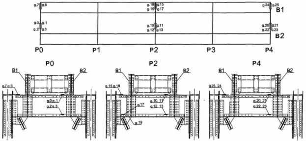
Static tests were carried out in «windows» with a duration of 2 hours. Two shunting diesel locomo-tives ChME-3 were used as a test load. Schemes of arrangement of strain gages during the span struc-ture static tests are shown in Fig. 2–4.
Findings
spanned by two metal deck structures, with design span of 44.0 m.
The railway bridge across the Mokraya Mosk-ovka River was built in 1903 according to one-span scheme of 1×88 m, then subjected to disrup-tion in 1920 and 1943. In 1948, the bridge was re-built according to the scheme of 2×44.0 m.
The total length of the bridge is 107.96 m. Ac-cording to the design, span structures are equal. Span structures consist of two through riveted deck trusses, with a triangular grid, as well as additional
posts. The distance between the trusses is 4.0 m, the truss height is 8.5 m. The trusses are made ac-cording to the project of the Proyektstalkon-struktsiya for L7 load. The booms have H-shaped section. Longitudinal horizontal connections be-tween the trusses are located in the level of the top and bottom booms, and the transverse connections in the even truss points in the form of intersecting diagonals.
The track way consists of staged-located I-section riveted stringers and floor beams.
Fig. 2. Arrangement of strain gages during span structure static tests
a b
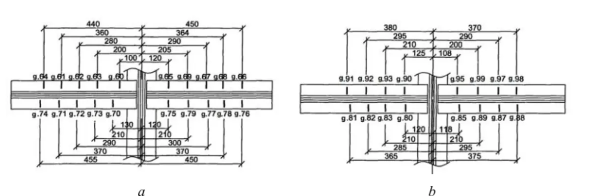
Fig. 3. Arrangement of strain gauges: on the stringer B1; a – on the left stringer B 1
a b
Fig. 4 Arrangement of strain gauges: on the left B1 and right B2 stringers at the point of support on the floor beam P4:
a – left stringer B1 in connection with P4
b – right stringer B2 in connection with P4
The stringer is fixed to the floor beam with four bolts. The distance between the stringers is 2.0 m.
The bridge substructures are double-track, mas-sive. The buried abutments are built on a natural foundation. The substructure underlying is granite, the intermediate substructure is concrete, massive, built in 1948, the pole footing is sunk shaft.
Prior to testing, the bridge crossing was sur-veyed, which included full-scale inspection of span structures, bridge substructures and supports, sur-vey of the river bed and approaches to the bridge, survey of the state of the bridge and the track way on the bridge and approaches [5, 8, 13].
The common defect of both span structures is the corrosion of the horizontal sheets of the bottom and top booms of the main trusses up to 1 mm, the paint peeling on the main truss elements, the con-tamination of the horizontal surfaces of the facings, the flanges with loose goods, and the unsatisfac-tory drainage of moisture from the booms.
One of the most significant detected defects is a disorder in the track way beam intersections.
Rivet ruptures, loose bolts, development of cracks along the flange angles pad eyes of the stringers at the points of their connection with the floor beams have been registered in the survey since 1958. Some cracks were drilled during the operation of the bridge, and later cuts were made in the bottom flange angles of the stringers. However, the development of cracks continues: along the left stringers at the floor beam P3 on the span structure 0–1 and at the floor beams P1, P3, P7 on the span structure 1–2 and along the right stringer at the floor beam P5 on the span structure 0–1. The
length of some cracks after cutting the flange angle web reaches 128 mm. In the bottom flange angles at the stringer-beam intersections P0 and P3, the development of cracks continues and the length of the cracks reaches 90 mm.
The loose bolts were found: along the left stringers at the floor beams P1 – 4 pcs., P3 – 8 pcs., P6 – 6 pcs., P7 – 12 pcs. on the span struc-ture 0–1 and at the floor beams P3 – 8 pcs., P7 – 6 pcs. on the span 1–2; and along the right string-ers at the floor beams P5 – 4 pcs., P7 – 5 pcs. on the span of 0–1.
Gaps were found in stringer-beam intersec-tions: along the left stringers at the floor beams P3 – 1.0 mm, P7 – 1.5 mm on the span structure 0–1 and at the floor beams P3 – 2.0 mm, P7 – 1 mm on the span 1-2; and also, along the right stringers at the floor beams P5 – 1.0 mm, P7 – 1.0 mm on the span structure 0–1 and at the floor beam P6 – 1.0 mm on the span structure 1–2.
Simultaneous presence of loose bolts, cracks and looseness in beam support was found: along the left stringers at the floor beams P3, P7 on the span structure 0–1 and at the floor beam P3 on the span structure 1–2; and along the right stringer at the floor beam P5 on the span structure 0–1.
In addition, on the span 0–1 in the beam grid, the following defects were found:
1) wear of gaskets under angle fishplates along the left stringers at the floor beams P1 – 1 mm, P3 – 2 mm, P6 – 2 mm, P8 – 1 mm;
3) on the right stringer at the junction of the floor beam P7 instead of 8 cut rivets there are in-stalled high-strength bolts;
4) curvature of the top flange angles on the left stringer in panels 6–7 and 7–8 to 20 mm;
5) in the joints of the top fishplates of the left stringers, in the panels 6–7 and 7–8 one rivet is missing, the right stringers in the panel 6–7 2 rivets are missing, in the panel 7–8 – one rivet.
On the span structure 1–2, the wear of gaskets under angle fishplates along the left stringers at the floor beams reaches: P2 – 1 mm, P3 – 1.5 mm, P5 – 2 mm, P7 and P8 – 1 mm.
In a number of places on the span structure 0–1, on unchanged upper sway struts between the stringers, there are local curvatures of the horizon-tal covers resulting from the derailment of the roll-ing stock in 1985.
On the span 0–1 in the first three panels, the longitudinal links between the main trusses have a sagging of up to 30 mm and local curvatures, ap-parently resulted from dropping downwards of the bridge deck debris in the course of restoration work after the derailment in 1985.
Due to the presence of cracks in the beam grid, there is a speed limit of up to 50 km/h on the bridge.
Static deflections were measured along the bot-tom flanges at the points L4 of both trusses. The highest deflection under the locomotive was 12 mm on both trusses. When converting to L7 load,
the relative deflection is 1/3000 lp, which is below
the limit value established by the norms.
When testing the track way beams, their stress state was determined, taking into account the joint work with the main trusses and the operation fea-tures of the bottom flange angles of the stringers in the points of their intersection with the floor beams. The loading patterns for the tests are shown in Fig. 5.
For the end floor beam P0, which is the most intensively involved in joint work with the truss booms, an unfavorable test load setting became the loading according to pattern 6.
In this case the greatest stresses in the flange angles reached +49.5 (p. 2) MPa and –63.7 MPa (p. 1). The stress state of the floor beam P0 for var-ious loading patterns is given in Table 1.
Fig. 5. Test loading patterns for span 0–1 Table 1 Stress from the static load in the floor beam P0, MPa
Check points No. of
scheme 0 (in) 1 (in) 2 (out) 3 (out) 1 –20.2 –27.4 30.6 6.7
2 1.9 –21.2 23.1 –4.2
3 3.4 –47.1 42.0 –5.7
4 3.9 –41.5 36.8 –8.9
5 19.3 –40.1 31.6 –16.0
6 13.0 –63.7 49.5 –3.8
7 37.6 –32.5 17.4 –22.6 8 31.3 –22.6 12.5 –18.1 9 29.4 –18.9 10.7 –14.3
The analysis shows that in addition to the verti-cal bending of the beam, there is a significant in-fluence of the horizontal bending and torsion of floor beams arising from the joint work of the track way beams with the booms of the main trusses, both at the P0 beam and at other beams.
the center of gravity. The rotation of the support sections of the stringers corresponds to the longi-tudinal displacements of their bottom surfaces and the same horizontal displacement of the attached top surfaces of the floor beams. Because of this, the floor beams work in horizontal bending with torsion and at the same time prevent the turns of the support sections of the stringers. The reason for this is the inclusion of stringers in joint work with the truss booms [1].
When the span is loaded with a vertical load, the compressed truss booms are shortened in each
panel by a value of δ. The presence of stringers,
the length of which remains practically unchanged under the load, prevents the free movement of the floor beams, which are attached to the booms of the main trusses. The difference of displacements
Δδ of truss booms and the track way stringers
causes bending of the floor beams in the horizontal plane.
The greatest bending moments in the horizontal plane occur in the extreme floor beams [1]. In the stringers the additional compressive forces appear, and in the booms of the main trusses the compres-sive forces are reduced. The bending of the string-ers causes the torsion of the floor beams, as well as the rotations of the attachment points and the de-formation of bends of the main truss booms in their plane. Bending corresponds to shear forces, which
decompose into longitudinal forces leading to the displacement of the points of the trusses.
When studying the stresses, the special atten-tion was paid to the determinaatten-tion of stresses in the bottom flange angles of the stringers near their at-tachment to the floor beams, since it is in these zones that the basic disorders (cracks, looseness in support and attachment of beams) are concen-trated. For this purpose, the short base strain gauges were pasted along the lower flange angles on the fillets of the stringers B1 and B2 at their junction points to the floor beam P4.
Loading of the span structure was carried out according to patterns 1–7 (Figure 5) with setting of the first axis of the locomotive every 5.5 m.
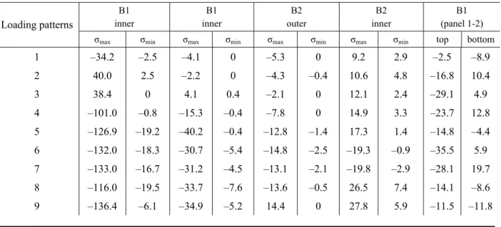
The stressed state of the track way beam ele-ments of the staged connection is determined by the lateral force and the bending moment acting in this zone. The moment arises from the fact that the stringers are not continuous, and also due to the features of the stringer-beam intersection operation (presence of gaps in the support, fishplate wear, the leakage of the stiffener edges, etc.). The maximum stresses in the stringer-beam intersections occur when the span is loaded according to the pattern 9 and reach –136.4 MPa in p.60. For all loading pat-terns, the highest experimental values of local stresses in the intersection of stringers B1, B2 with floor beam P4 are given in Table 2.
Table 2 The highest stresses in the intersections of stringers B1 and B2 with floor beam P4 and stringer B1
(panel 1-2), MPa
B1 inner
B1 inner
B2 outer
B2 inner
B1 (panel 1-2) Loading patterns
σmax σmin σmax σmin σmax σmin σmax σmin top bottom
1 –34.2 –2.5 –4.1 0 –5.3 0 9.2 2.9 –2.5 –8.9
2 40.0 2.5 –2.2 0 –4.3 –0.4 10.6 4.8 –16.8 10.4
3 38.4 0 4.1 0.4 –2.1 0 12.1 2.4 –29.1 4.9
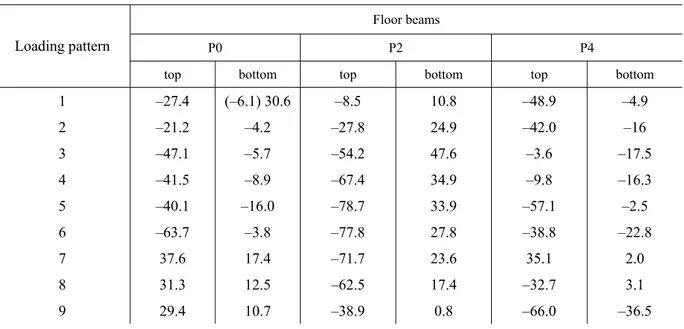
Table 3 The highest stresses in track way floor beams, MPa
Floor beams
P0 P2 P4 Loading pattern
top bottom top bottom top bottom
1 –27.4 (–6.1) 30.6 –8.5 10.8 –48.9 –4.9
2 –21.2 –4.2 –27.8 24.9 –42.0 –16
3 –47.1 –5.7 –54.2 47.6 –3.6 –17.5
4 –41.5 –8.9 –67.4 34.9 –9.8 –16.3
5 –40.1 –16.0 –78.7 33.9 –57.1 –2.5
6 –63.7 –3.8 –77.8 27.8 –38.8 –22.8
7 37.6 17.4 –71.7 23.6 35.1 2.0
8 31.3 12.5 –62.5 17.4 –32.7 3.1
9 29.4 10.7 –38.9 0.8 –66.0 –36.5
The stresses vary unevenly along the angles. The greatest stresses occur, as a rule, at the ends of the angles. In some cases, the maximum and local stresses in the angles were at a distance of 80–100 mm from the angle edges. In most cases, the change in stresses in the angles along their length is characterized by a change in the stress sign.
In addition to measurements of deformations (stresses) in the end floor beam P0, the stresses in the left stringer B1 in the panel 1–2 and in the floor beams P2 and P4 were determined during the tests.
According to the measurement results, in the stringer, in addition to stresses from the vertical bending moment, there are stresses from the action of other factors (horizontal bending, axial forces and torsion of the floor beam).
For the various loading patterns, the highest stresses in the intersections of the stringers B1 and B2 with the floor beam P4 and in the stringer B1 (panel 1–2) are shown in Table 2. The highest stresses in the floor beams P0, P2 and P4 obtained during testing are given in Table 3.
Axial compressive stresses in the stringers arise due to their joint work with the booms of the main trusses. This causes a bending in the horizontal direction of the floor beams. This is manifested the most for the floor beam P2 at its connection with the truss F1, and in the middle of the span of this
beam the effect of the horizontal bend is lower (see Table 3).
The maximum stresses from all the loads are recorded in the floor beam P2 at its connection with the truss F1 and amounted to -131.5 MPa at point 15 (pattern 9) and +105.3 MPa at point 17 (pattern 9).
In the stringer B1, the maximum stresses were recorded in the middle of panel 1-2 and amounted to -35.5 MPa at point 30 (pattern 6) and +19.7 MPa at point 33 (pattern 7) (see Fig. 3 and Fig. 5).
Originality and practical value
Vertical deflections of the main trusses when the span structure was loaded with a movable load (two sections of locomotive TEZ + 4-axle loaded gondola cars) reached a value of 12.4 mm,
1/3500 lp. While testing the span under the train
load, there are significant additional stresses from horizontal bending of floor beams and their torsion in the floor beam flanges. The appearance of these stresses is caused by inclusion of stringers into coupled work with top booms.
Conclusions
The stressed state of the floor beams P0, P2, P4 is determined mainly by vertical bending. Stresses from horizontal bending and torsion appear from the joint work of the track way beams with the booms of the main trusses.
The most significant stresses are obtained from the horizontal bending in the floor beam P2 at the point of its connection to the truss F1. The highest stress values here are obtained in the angle of the top boom P2 at point 15 when the span is loaded according to the pattern 9. In a greater degree the horizontal bending of the floor beams affects the stress values in the horizontal webs of the top flange angles with which the floor beams are at-tached to the gusset plates of the upper longitudinal ties between the main trusses. Here, the effect is that the span structures installed on this bridge have very small distance from the stringer axis to its connection to the truss.
A high level of stresses in the top flanges of the floor beams explains the appearance of a crack in the horizontal web of the top flange angle in the section between the stringer and the truss [9, 11, 15].
The stress state in the middle of the panel 1–2 of the stringer B1, where during the tests the meas-urements were performed, is relatively low. Here the stress values are no more than 30–40 MPa.
In those places where the cracks have already appeared it was not possible to measure the stress-es. The measurements were taken mainly at the points of support of the stringers on the floor beam P4, where cracks in the bottom flange angles of the stringers were not observed during inspection. In these places, a detailed study of the stress state was carried out. The strain gauges were pasted at 32 points on the fillets at the ends of the bottom flange angles on both sides of each stringer every 80–100 mm.
Stresses in the angles proved to be very high (up to 136.4 MPa). It should be noted that the con-nection of stringers with a floor beam P4, obvi-ously, is not the most stressful point, because in this place, instead of the stringer bottom angle fish-plates there are extended gusset fish-plates for break connections. This is particularly significant as the design of the span structures did not include the checks of the stresses in these places. In other con-nections, where cracks are already observed in the angles the stresses appeared to be even higher.
All this indicates that the design of the intersec-tion between the track way beams and the staged arrangement of the stringers and floor beams ap-plied on the bridge is unsuccessful and requires an increase in the reliability of the joint structures.
LIST OF REFERENCE LINKS
1. Бычковский, Н. Н. Металлическиемосты / Н. Н. Бычковский, А. Ф. Данковцев ; Сарат. гос. техн. ун-т. –Саратов, 2005. – Ч. 1. – 364 с.
2. Гибаленко, А. Н. Оценкаживучестиметаллоконструкцийпримоделированиифакторовэксплуатации / А. Н. Гибаленко, Т. С. Трофимчук // Наука тапрогрес транспорту. – 2016. – № 2 (62). – С. 119–128. doi: 10.15802/stp2016/67327.
3. ГСТУ 32.6.03.111-2002. Експлуатація залізничних мостів. Правила визначення вантажопідйомності металевихпрогоновихбудовзалізничнихмостів. – Чиннийвід 2001–12–05. – Київ : М-вотрансп. Укра -їни, 2003. – 382 с.
4. ДБНВ.1.2-15:2009. Спорудитранспорту. Моститатруби. Навантаженняівпливи. – Чиннийвід 2009– 11–11. – Київ : МінрегіонбудУкраїни, 2009. – 83 с.
5. ДБНВ.2.3-6:2009. Моститатруби. Обстеженняівипробування. – Чиннийвід 2009–11–11. – Київ : М -ворегіон. розвиткутабуд-ваУкраїни, 2009. – 43 с.
6. ДБН В.2.3-14:2006. Споруди транспорту. Мости та труби. Правила проектування. – Чинний від 2007–02–01. – Київ : М-вобуд-ва, архітектуритажитл.-комун. госп-ва, 2006. – 359 с.
7. Ефимов, П. П. Проектированиемостов / П. П. Ефимов. – Омск : Дантэя, 2006. – 111 с.
8. Інструкціязвизначенняумовпропускурухомогоскладупометалевихтазалізобетоннихзалізничних мостах / Гол. упр. колійн. госп-ваУкрзалізниці. – Київ : М-вотрансп. України, 2002. – 301 с.
10. Ключник, С. В. Обзор варіантів підсилення та ремонту балок проїзної частини поверхового типу / С. В. Ключник, В. В. Марочка // Мостита тунелі: теорія, дослідження, практика. – 2014. – Вип. 5. – С. 35–40.
11. Пат. 109806 Україна, МПК E 01 D 1/00, E 01 D 19/00, E 01 D 101/30. Вузолспиранняпоздовжньоїбал -кинапоперечну / МарочкаВіталійВладиславович, КлючникСергійВладиславович ; заявниктапатен -товласник Дніпропетр. нац. ун-т залізн. трансп. ім. акад. В. Лазаряна. – № u 2016 01940 ; заявл. 29.02.2016 ; опубл. 12.09.2016, Бюл. № 17.
12. Проблемиресурсуібезпекиексплуатаціїконструкцій, спорудтамашин [Electronic resource] : зб. наук. ст. / Ін-т електрозварювання ім. Є. О. Патона НАН України. – Київ, 2015. – 816 с. – Available at: http://patonpublishinghouse.com/rus/compilations/resurs2015. – Title from the screen. – Accessed : 29.05.2017.
13. Шульман, 3. А. Испытанияимониторингинженерныхсооружений / 3. А. Шульман, И. 3. Шульман. – Днепропетровск, ЛИРА, 2013. – 536 с.
14. Gibalenko, A. N. Design requirements to structural steel durability based on level of industrial facility corro-sion hazard / A. N. Gibalenko, V. Korolov, J. Filatov // Aktualnie problemy konstrukcji metalowych : Abstr. II Polish-Ukrainian International Conference APMK (27.11– 28.11.2014) / University of Technology. – Gdansk, 2014. – Р. 98–102.
15. Ovchinnikov, P. Sing of finite element modeling for determination of buckling possibility in lengthwise stiff-eners of orthotropic plate for bridge spans under operational load / P. Ovchinnikov, S. Klyuchnik // Мостита тунелі: теорія, дослідження, практика. – 2012. – Вип. 5. – С. 130–135.
16. Rust, I. Sicherheit technischer Anlagen – Eine sozial wissenschaftliche Analyse des Umgangs mit Risiken in Ingenieurpraxis und Ingenieurwissenschaft / Ina Rust ; Kassel university. – Kassel, 2004. – 394 p.
17. Weltschev, M. Comparison of the operating life of tank containers, tank vehicles and rail tank cars for the car-riage of dangerous goods in practice, analysis of causes of damage / М. Weltschev, S. Schwarzer, F. Otremba // Chemical Engineering Transactions. – 2013. – Vol. 31. – Р. 559–564. doi: 10.3303/CET1331094.
С
.
В
.
КЛЮЧНИК
11ГНДЛштучнихспоруд, Дніпропетровськийнаціональнийуніверситетзалізничноготранспортуіменіакадеміка
В. Лазаряна, вул. Лазаряна, 2, Дніпро, Україна, 49010, тел. +38 (050) 667 40 49, ел. пошта ssser05@ukr.net, ORCID 0000-0001-7771-8377
ДЕФОРМАЦІЙНО
-
НАПРУЖЕНИЙ
СТАН
ВУЗЛА
ПОВЕРХОВОГО
СПОЛУЧЕННЯ
БАЛОК
ПРОЇЗНОЇ
ЧАСТИНИ
ЗАЛІЗНИЧНОГО
МОСТА
-левихбалокпроїзноїчастиниповерховогорозташуваннязурахуваннямспільноїроботибалокізнесучими фермами. Практична значимість.При випробуванніпрогоновоїбудови поїзним навантаженнямупоясах поперечнихбалокз’являютьсязначнідодатковінапругивідгоризонтальноговигинупоперечнихбалоктаїх крутіння. Появацихнапруженьпов’язаназвключеннямпоздовжніхбалокуспільнуроботузверхнімипо -ясамиферм. Виникаючідефективпоздовжніхбалкахпов’язанізконцентрацієюмісцевихнапруженьчерез конструктивніособливостіповерховоїпроїзноїчастини.
Ключовіслова:поздовжнібалки; деформація; напруження; поперечнібалки; металевіпрогоновібудови
С
.
В
.
КЛЮЧНИК
1*1*ОНИЛискусственныхсооружений, Днепропетровскийнациональныйуниверситетжелезнодорожноготранспорта
имениакадемикаВ. Лазаряна, ул. Лазаряна, 2, Днипро, Украина, 49010, тел. +38 (050) 667 40 49,
ел. почта ssser05@ukr.net, ORCID 0000-0001-7771-8377
ДЕФОРМАЦИОННО
-
НАПРЯЖЕННОЕ
СОСТОЯНИЕ
УЗЛА
ЭТАЖНОГО
СОПРЯЖЕНИЯ
БАЛОК
ПРОЕЗЖЕЙ
ЧАСТИ
ЖЕЛЕЗНОДОРОЖНОГО
МОСТА
Цель.Этажноесопряжениебалокпроезжейчастижелезнодорожныхмостовнаиболеепростоепоконст -рукции, новследствиеконструктивныхнедостатковподверженомногочисленнымдефектам. Цельюданной работы является исследование фактического деформационно-напряженного состояния узла сопряжения продольныхбалокспоперечнымиприихэтажномрасположении. Необходимотакжеопределитьвозможное влияние совместной работы поясов ферм и балочной клетки мостового полотна на их деформационно -напряженноесостояние. Методика. Длядостиженияпоставленнойцелипроведеныиспытаниясуществую -щего моста. Для измерения деформаций (напряжений) в элементах пролетного строения использовались тензорезисторы, наклеенныенапоясныхуголкахпоперечныхипродольныхбалокинавыкружкахнижних поясныхуголков продольныхбалокв местахопиранияихнапоперечныебалки. Дляизмерения прогибов ферм, продольныхипоперечнойбалокпристатическихиспытанияхиспользовалисьпрогибомерыАистова и Максимова, которые устанавливались по нижним поясам ферм в середине пролетного строения 0–1, атакжена обеих продольных иодной поперечной балках в серединепролета. Прогибомеры крепились к пролетномустроениюисоединялисьпроволочнымисвязямисповерхностьюгрунта. Результаты.Автором полученоипроанализированодеформационно-напряженноесостояниеузласопряженияпродольныхбалок споперечнымиприихэтажномрасположении. Анализпоказывает, чтопомимовертикальногоизгибабалок имеетместозначительноевлияниегоризонтальногоизгибапоперечныхбалокиихкручения, возникающие вследствиесовместнойработыбалокпроезжейчастисверхнимипоясамиглавныхферм, какубалкиП0, так иудругих балок. Научная новизна.В работепроведеноисследованиенапряженно-деформационногосо -стоянияметаллических балокпроезжейчасти этажногорасположения сучетом совместной работы балок снесущимифермами. Практическая значимость.При испытаниипролетного строенияпоезднойнагруз -койвпоясахпоперечных балокпоявляютсязначительныедополнительныенапряженияотгоризонтального изгиба поперечныхбалок иих кручения. Появление этихнапряжений связанос включениемпродольных балоквсовместнуюработусверхнимипоясамиферм. Возникающиедефектывпродольныхбалкахсвязаны сконцентрациейместныхнапряженийиз-законструктивныхособенностейэтажнойпроезжейчасти.
Ключевые слова: продольные балки; деформация; напряжения; поперечныебалки; металлические про -летныестроения
REFERENCES
1. Bychkovskiy, N. N., & Dankovtsev, A. F. (2005). Metallicheskiye mosty. Saratov: Yuri Gagarin State Techni-cal University of Saratov.
2. Gibalenko, O. M., & Trofymchuk, T. S. (2016). Metal structures survivability assessment when simulating service conditions. Science and Transport Progress, 2(62), 119-128. doi: 10.15802/stp2016/67327
3. Ekspluatatsiia zaliznychnykh mostiv. Pravyla vyznachennia vantazhopidiomnosti metalevykh prohonovykh sporud zaliznychnykh mostiv, GSTU 32.6.03.111-2002 (2003).
6. Sporudy transportu. Mosty ta truby. Pravyla proektuvannia, DBN V.2.3-14:2006 (2006). 7. Yefimov, P. P. (2006). Proektirovaniye mostov. Omsk: Danteya.
8. Ukrzaliznytsia. (2002). Instruktsiia z vyznachennia umov propusku rukhomoho skladu po metalevykh ta zal-izobetonnykh zaliznychnykh mostakh. Kyiv: Ministry of Infrastructure of Ukraine.
9. Kliuchnyk, S. V., & Marochka, V. V. (2012). Opyt ekspluatatsii etazhnoy proezzhey chasti. Proceedings of the
72 International Scientific & Practical Conference «Problems and Prospects of Railway Transport Develop-ment«, April 19-20, 2012, Dnipropetrovsk. 158.
10. Kliuchnyk, S. V., & Marochka, V. V. (2014). Review of enhancement and repair options for roadway beams of two-level type. Bridges and Tunnels: Theory, Research, Practice, 5, 35-40.
11. Marochka, V. V., & Kliuchnyk, S. V. (2016). UA Patent No.109806. Ukrainian Intellectual Property Institute (UKRPATENT).
12. Paton Electric Welding Institute of the National Academy of Sciences of Ukraine. (2015). Service life and safety of structures, buildings and machinery. Kyiv: Paton Publishing House. Retrieved from http://patonpublishinghouse.com/rus/compilations/resurs2015
13. Shulman, Z. A., & Shulman, I. Z. (2013). Ispytaniya i monitoring inzhenernykh sooruzheniy. Dnipropetrovsk: LIRA.
14. Gibalenko, A. N., Korolov, V., & Filatov, J. (2014). Design requirements to structural steel durability based on level of industrial facility corrosion hazard. Proceedings of the II Polish-Ukrainian International Conference Aktualnie problemy konstrukcji metalowych (APMK), November, 27-28, 2014, Gdansk. Gdansk: University of Technology.
15. Ovchinnikov, P., & Kliuchnyk S. (2014). Using of finite element modeling for determination of buckling pos-sibility in lengthwise stiffeners of orthotropic plate for bridge spans under operational load. Bridges and Tun-nels: Theory, Research, Practice, 5, 130-135.
16. Rust, I. (2004). Sicherheit technischer Anlagen – Eine sozial wissenschaftliche Analyse des Umgangs mit Risiken in Ingenieurpraxis und Ingenieur wissenschaft. (Doctoral dissertation). Kassel University, Germany. 17. Weltschev, M., Schwarzer, S., & Otremba, F. (2013). Comparison of the operating life of tank containers, tank
vehicles and rail tank cars for the carriage of dangerous goods in practice, analysis of causes of damage.
Chemical Engineering Transactions, 31, 559-564. doi: 10.3303/CET1331094
Prof. V. D. Petrenko, D. Sc. (Tech.), (Ukraine); Prof. V. Ye. Volkova, D. Sc. (Tech.), (Ukraine) recommended this article to be published