TECHNICAL UNIVERSITY OF CLUJ-NAPOCA
ACTA TECHNICA NAPOCENSIS
Series: Applied Mathematics, Mechanics, and Engineering Vol. 61, Issue III, September, 2018
INFLUENCE OF THE MICROGEOMETRY ON THE DRILLING PROCESS
IN INCONEL 718
Vlad-Bogdan TOMOIAGĂ, Marcel Sabin POPA, Glad CONȚIU, Adrian Sorin FAUR, Stefan SATTEL
Abstract: The process of cutting different material is getting difficult due the good mechanical properties of the new material. According to the evolution of the aeronautical and automotive industry, the materials had to be improved in order to keep the tendency. In parallel, it was necessary to improve the properties of the cutting tools that process this material. Four major directions are intended to be studied in case of the work tools: base material, coating, geometry and microgeometry. The researches have shown that all have a great importance in determining the best durability of the work tool. The article is trying to emphasize the role of the microgeometry in processing the Inconel 718. The material presents difficult cutting properties due to its mechanical and physical properties. One of the machining results is durability, the surface quality and on this criterion will be evaluated the best microgeometry used in drilling the Inconel 718
Key words: Drill, K Factor, cutting edge, microgeometry, wear.
1. INTRODUCTION
Due to the fact that it has some very good mechanical properties, the processing of Inconel 718 is very difficult and also the durability of the cutting tools is low. It’s used in various industries, especially in the aeronautics industry. That stimulates the researchers to focus on developing new tools that can achieve a suitable durability. This means that the work tool has to have optimal properties in all four variables: base material, coating, geometry and microgeometry. In paper [1, 2] are presented the effects cutting parameters and cutting edge preparation for machining Inconel 718. One of the processes that the researchers focused on was the drilling process. In various works the durability of the cutting tools was studied, but also the roughness of the machined surfaces on different type of materials. During the drilling process the quality of the hole depends on the type of the drill: macrogeometry, microgeometry, material of the drill, but also on the material of the workpiece. One of the studies
was by Biermann et al., which was focused on drills with a diameter of 8.5 mm on drilling the
42CrMo4. In this study the authors has used drills with different microgeometry. They used K-factors 0.6, 1 and 1.4, with S ̅~35µm. The
The influence of the new geometry on the roundness deviation is small. Looking to the average surface roughness it seems that the extreme values are smaller in case of the modified tool [4]. Paper [5] presents a study with different macrogeometry of drills from different suppliers to bore in Inconel 718. The test from [5] shows which macrogeometry has a better tool life and the influence on the surface roughness. In paper [6] is presented the roughness of the machined surface in 42CrMo4 material on the milling process with different factors. Authors concluded that the lower the K-factor is, the better the surface quality can be achieved. Another paper where the surface roughness was studied is [7], where authors used different drill macrogeometry. There are also different papers where machining of Inconel 718 was studied [8, 9, 10, 11, 12, 13, 14].
This paper studied the influence of the K-factor in drilling process of Inconel 718 material. Authors studied the tool life but also the roughness evolution of the hole. In this experiment were used drills with 6.8 diameters and length 4xD. The K factor was chosen to have values of 0.5, 1 and 1.4.
2. MICROGEOMETRY
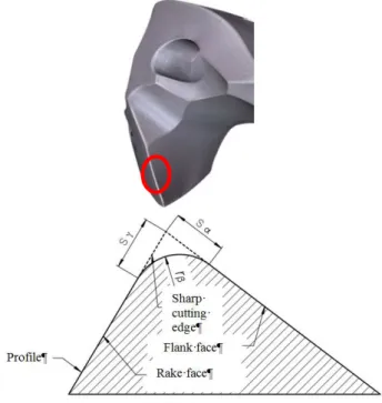
Cutting tools can have different macrogeometry or microgeometry. The microgeometry of the cutting edge can be divided in chamfer or rounding form. The rounded cutting edge is characterized by the radius rβ when it presents a
symmetrical edge and by Sα and Sγ for asymmetrical microgeometry. The parameters Sα and Sγ are determined by the intersection
point between the flank and rake face and the tangents from where the rounding begins as it can be observed in fig. 1.
K-factor is defined by the relation: S
K S
γ
α
= . (1)
[15]
rβ – radius of the cutting edge
Sα - cutting edge segment on the flank face Sγ - cutting edge segment on the rake face
S− - average cutting edge rounding
∆r - profile flattening φ - apex angle
When K>1 the cutting edge has the tendency to the rake face and when K<1 has the tendency to the flank face [16]. Microgeometry can be prepared with different process: mechanical thermic and chemical [17, 18, 19]. In the industry, the most used cutting edge preparation is the mechanical ones due to its precision and reduced time.
Fig. 1. Microgeometry of the cutting edge.
3. EXPERIMENTAL DATES
For this experiments were used rectangular boards from Inconel 718. In order not to have influence coming from the cutting material, all the material was prepared in the same batch. As in case of the cutting material, all the drills are made from the same carbide in the same batch and also the cutting zone has the same macrogeometry. For the microgeometry of the drills was followed to be the same condition for surface treatment and polishing process for all K-factors. For the cutting edge preparation was followed to change as few parameters as possible. After the drills were prepared and polished, they were coated and the microgeometry was measured. In this paper were used K≈0.5, K≈1and K≈1.4 and the radius
to the nominal value and the radius rβ which were measured with an optical microscope. Another criterion was the surface quality and last but not the least the surface integrity that was inspected on electronic microscope. After the coating, the rake face of the drills was measured to determine the surface roughness. Fig. 2 presents the roughness surface of the rake face for the 6.8 mm drills, results being according with DIN 4287.
It can be observed a similarity between the values of the drills with K≈0.5 and the drills with symmetrical microgeometry and the highest values are obtain for drills with K≈1.4. The
explanation of these results is that drills with K≈1.4 are more surface treated on the rake face then the other two type of microgeometry.
Fig. 2. Roughness surface of the rake face.
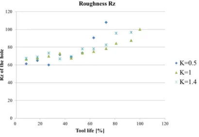
In fig. 3 it can be observed the influence of the microgeometry on the roughness Rz and Ra of the holes in relationship with the tool life. For
each K-factor were studied three drills and in the graph from fig 3 is represented the mean value of the Ra and Rz. All the values are in percentage and all the values are reported to the standard microgeometry that is considered heaving a K factor equal to 1. The maximum tool life and roughness of the hole for the standard drill were considered with 100%. The surface roughness was measured at predetermined intervals. In fig. 3 a) can be noticed that until 50% of the tool life, all the roughness values are approximately the same. After the half of the total tool life, the roughness Rz tends to increase for drills with K≈0.5. That means that the tool wear begins to
increase and that’s the main reason for lower surface quality when are utilized drills with K≈0.5. Between drills with K≈1 and K≈1.4 the
differences are not highlighted. At the end of the tool life, the results are representative for the tools with K≈0.5, but for the other two K≈1 and
K≈1.4 the differences are not significant. The study can be compared with the study made by Biermann in [3] where it was studied the influence of the process parameters.
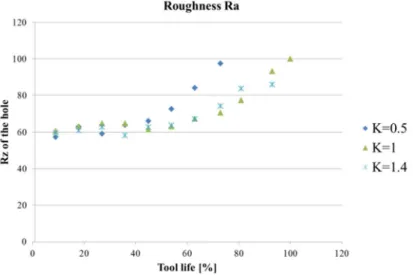
Fig. 3 b) shows that the surface roughness Ra has the same evolution like Rz with the difference that at the end of the experiments better surfaces is obtained with drills with K-factor 1.4, but these drills have lower tool life than the standard drills.
b) Roughness Ra
Fig. 3. Surface roughness of the hole.
As a conclusion regarding the surface quality and tool life is that the K factor equal to 1 can achieve the highest tool life but a bigger K factor is increasing the surface quality without drastically reducing the tool life. This means that in case of a mass production can be given a nominal value of K factor of 1.2.
Fig. 4 presents the cutting edge at the end of the tool life with similarities for all three K factors: built-up edge on the flank face. At the beginning of the experiments there was not so obvious, but drilling more holes this phenomena could be seeing.
Fig. 4. Overview of the cutting edge at the end of experiments.
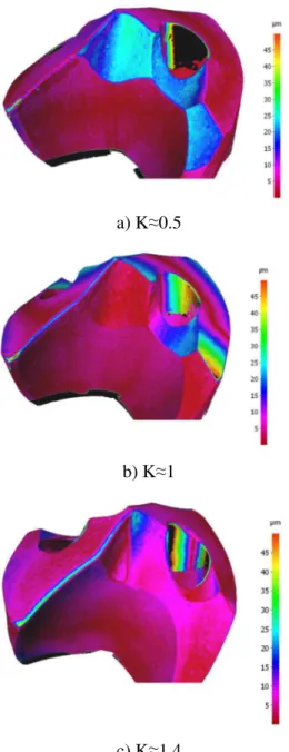
To have a better behavior of the corner of the drill could be make different geometry only in that part of the drill, like for the flank face. Another analysis of this paper is “the 3D scanning of the drills”. After the experiments end they were again scanned 3D and compare to drills before the experiments start. This analysis can emphasize the wear of the work tool during the entire process or the material deposition after a period. The surface scanning equipment facilitates this analysis. In fig. 5 can be observed how the wear is more pronounced on the corner of the drills.
a) K≈0.5
b) K≈1
c) K≈1.4
Fig. 5. Comparison of the 3D scanned drills.
On the flank face the wear is not so notable; also on drills with K≈1.4 it can be noticed that near
the cutting edge the wear is more pronounced as in the other two cases, meaning that the tool life for this drills is smaller than in other cases, but looking on fig. 4 it’s not the case. That could mean that the wear is bigger only near to the cutting edge on a small part of the flank face and in rest could be more uniform than in in case of K≈1 and K≈0.5. This phenomenon appears when the material is compacted under the force under the flank face.
4. CONCLUSION
After this experiments the authors could say that the in case of quality of the rake face the surface roughness is better for drills with K≤1, because the surface of the rake face of the drill is treated more intensively. Looking at the surface roughness of the machined material and tool life of the tool, we could say there is not obvious difference between the results the studied microgeometry, but some remarks could be made like better quality of the surface of the hole is obtained with drills that have K-factor ≥1.
Also in all three cases on the flank faces appear material deposition and all the corner of the drill break up or are tending to break up. The problem could be solved by changing the cutting parameters, coating material, or improving the geometry of the drill.
5. ACKNOWLEDGMENT
This work is part of a research project, and PhD work, for the Technical University of Cluj-Napoca, with logistic and financial support received from the Gühring KG Company by offering the possibility to realize the entire test.
6. REFERENCES
[1] Coehlo, R.T., Silva, L.R., Braghini, A., Bezerra, A.A.,
Some effects of cutting edge preparation and geometric modification when turning Inconel 718 at high cutting speeds, Journal of material processing
technology 148: 147-153, 2004
[2] Pawade, R.S., Joshi, S.S., Brahmankar, R.K., Effect of machining parameters and cutting edge geometry on surface integrity of high-speed turned Inconel 718,
[3] Biermann, D., Denkena, B., Komplettpräparation von komplexen Zerspannungswerkzeugen III,
Abschlussbericht des Projektes, 2014 [German language].
[4] Beer, N., Özkaya, E., Biermann, D., Drilling of Inconel 718 with geometry-modified twist drills, Procedia
CIRP, 24: 49-55, 2014.
[5] Sharman, A.R.C., Amarasinghe, A., Ridgway, K., Tool life and surface integrity aspects when drilling and hole making in Inconel 718, Journal of materials
processing technology, 200:424-432, 2008.
[6] Fulemova, J., Rehor, J. Influence of Form Factor of the Cutting Edge on Tool Life during Finishing Milling,
Procedia Engineering 100: 682-688, 2015
[7] Biermann, D., Terwey, I., Cutting edge preparation to improve drilling tools for HPC processes, CIRP
Journal of Manufacturing Science and Technology, vol 1: 76-80, 2008
[8] Zetek,M., Česáková, I., ŠvarcIncreasing, V., Cutting Tool Life when Machining Inconel 718, 24th DAAAM International Symposium on Intelligent Manufacturing and Automation, Procedia Engineering
69 1115 – 1124, 2014
[9] Česáková I., Zetek, M., Švarc, V. Evaluation of the cutting tool when Inconel 718 is machined, IJET 2013,
Dubrovnik, ISBN 978-80-87670-08-8, 2013
[10] Woona, K.S., Chaudharib, A., Senthil Kumarb, A., Rahmanb, M., The Effects of Tool Degradation on Hole Straightness in Deep Hole Gundrilling of Inconel-718, Procedia CIRP 14: 593 – 598, 2014
[11] Yunlu, L., Çolak, O., Kurbanoglu, C., Taguchi DOE Analysis of Surface Integrity for High Pressure Jet Assisted Machining of Inconel 718, Procedia CIRP 13
333 – 338, 2014
[12]Le Coz, G., Marinescu, M., Moufki, A., Dudzinski, D., Residual stresses after dry Machining of Inconel
718, experimental results and numerical simulation,
Conference Paper, 2010
[13] Parida, A.K., Maity, K., Effect of nose radius on forces, and process parameters in hot machining of Inconel 718 using finite element analysis, Engineering
Science and Technology, an International Journal, 2016
[14] Baghlania, V., Mehbudia, P., Akbarib, J., Sohrabic, M., Ultrasonic assisted deep drilling of Inconel 738LC superalloy, Procedia CIRP 6 571 – 576, 2013
[15] Denkena, B., Biermann, D., Cutting edge geometries,
CIRP Annals – Manufacturing Technology 63 631-653, 2014
[16] Denkena, B., Köhler, J., Ventura, C.E.H., Customized cutting edge preparation by means of grinding,
Precision Engineering 37: 590-598, 2013
[17] Cortes, R., Cutting Edge Preparation of Precision Cutting Tools by Applying Micro-abrasive Jet Machining and Brushing, (PhD Thesis) Universität
Kassel, Kassel University Press, Kassel, 2009 [18] Tikal, F., Bienemann, R., Heckmann, L.,
Schneidenkantenprepräparation Ziele, Verfahren und Messmethoden, Berichte aus Industrie und Forschung,
Kassel: Kassel University Press, 2009 [German language].
[19] Ramesh, V., Cutting edge preparation, Proceedings
of 30th The IIER International Conference, Beijing, China, 26th July 2015, ISBN: 978-93-85465-57-4 [20] Liao, Y.S., Shiue, R.H., Carbide tool wear
mechanism in turning of Inconel 718 superalloy, Wear
193, 16–24, 1996
[21] Sharman, A., Hughes, J., Ridgway, K., Workpiece surface integrity and tool life issues when turning Inconel 718 nickel based superalloy. Mach. Sci.
Technol. 8 (3), 399–414, 2004
Influența microgeometriei în procesul de burghiere a materialului Inconel 718
Procesul de așchiere a diferitelor materiale, devine din ce în ce mai dificil din cauza bunelor proprietăți mecanice ale noilor materiale.Potrivit evoluției industriei aeronautice și auto, a fost necesară îmbunătățirea materialelor pentru a ține pasul cu cerințele din aceste industrii. În paralel, a fost necesară și optimizarea proprietăților sculelor așchietoare care prelucrează aceste materiale. Se intenționează a se studia patru direcții majore în cazul sculelor așchietoare: materialul de bază, acoperirea, geometria și microgeometria. Studiile au arătat că toate acestea au o mare importanță în determinarea durabilității optime a sculelor. Acest articolul încearcă să sublinieze rolul microgeometriei în procesarea materialului Inconel 718. Acest material prezintă dificultăți în a fi așchiat datorită proprietăților sale mecanice și fizice. În cazul acestui material, durabilitatea și calitatea suprafeței reprezintă criteriul după care va fi evaluată cea mai bună microgeometrie pentru a burghiere a materialul Inconel 718.
Vlad-Bogdan TOMOIAGĂ, PhD Stud., Eng., Technical University of Cluj-Napoca, Department
for Manufacturing Technology, [email protected], Home Address: Cluj-Napoca, Home Phone 0751 201 046
Marcel Sabin POPA, Dr. Eng., Professor, Technical University of Cluj-Napoca, Department for
Manufacturing Technology, [email protected], Home Address: Cluj-Napoca, Home Phone 0264-401634
Glad CONȚIU, Dr., Eng., Lecture, Technical University of Cluj-Napoca, Department for
Manufacturing Technology, [email protected], Home Address: Cluj-Napoca
Adrian Sorin FAUR, PhD Stud., Eng., Technical University of Cluj-Napoca, Department for
Manufacturing Technology, [email protected], Home Address: Cluj-Napoca