TECHNICAL UNIVERSITY OF CLUJ-NAPOCA
ACTA TECHNICA NAPOCENSIS
Series: Applied Mathematics, Mechanics, and Engineering Vol. 61, Issue III, September, 2018
ACTUATION AND CONTROL OF A SERIAL ROBOTIC ARM WITH FOUR
DEGREES OF FREEDOM
Florin COVACIU
Abstract: The paper presents the actuation and control of a serial robotic arm. On the serial robot a gripper is attached with which small objects can be caught. The robot is controlled via a user interface, and to move the robot are made trajectories, next these trajectories are written in a text file. To repeat the robot trajectories, we must read the text file with the saved trajectories.
Key words: serial robotic arm, user interface, gripper, experimental model, actuation, control
1. INTRODUCTION
Robotics is a field of modern technology where the complexity of robots and their applications requires knowledge of mechanical
engineering, computer science, electrical
engineering, mathematics, systems and
industrial engineering. A robot is designed to move materials, tools and parts through variable programmed motions for the performance of a variety of tasks [1]. A key component is the control is robot control where a lot of development is made to increase the robot performance, introduce new functionalities and reduce robot costs. Model-based control is a key technology in the control of industrial robots where models and control schemes are continuously refined to meet the requirements on higher performance [2]. In industry, serial robots are mainly used for task that require good repeatability but not necessarily good global pose accuracy (position + orientation) of the robot end-effector. In general, these robots are used for welding, painting and pick-and-place operations [3]. A serial robot in its most general form consists of several rigid links connected by motor-actuated joints that extend from a base to
an end-effector. Often, they have an
anthropomorphic arm structure described as having a "shoulder", an "elbow", and a "wrist". Simplicity considerations in manufacturing and control have led to serial robots with only
revolute or prismatic joints and orthogonal, parallel and/or intersecting joint axes (instead of arbitrarily placed joint axes). The advantage offered by a serial robot consist in a large workspace with respect to the size of the robot and the floor space it occupies.
Industrial robots, in general are employed to carry out repetitive jobs and/or those that require precision and speeds difficult to achieve by human beings. This has made it possible to improve the quality of products and the
efficiency of their manufacturing [4].
Nowadays, industrial robots are increasingly used in modern and automated production processes, as well as in hazardous applications and can perform tasks during many hours per day without getting tired or losing precision or effectiveness, because they are currently highly developed and robust devices that practically do not fail [5].
The paper is organized as follow: First section presents the state of the art. Section 2 present the real model of the serial robot. Section 3 presents the control and actuation system continuing with the user interface in section 4, followed by conclusions and references.
2. THE EXPERIMENTAL MODEL OF THE SERIAL ROBOT
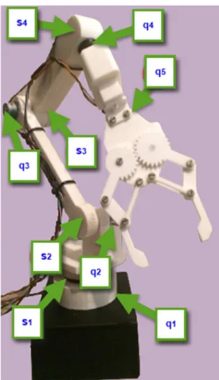
Fig. 1 Description of the serial robot
The motion of the robot is achieved using four actuators (q1, q2, q3, q4), which are the stepper
motors, that actuate for rotational joints. A servomotor (q5) is used to actuate the gripper.
The switch sensors (s1, s2, s3, s4) are used both as
stroke limits as well as to set the zero position of each axis of the robot.
The components of the robotic arm were built using a 3D printer, figure 2. The chosen material was PLA. This is a thermoplastic material, further classified as a polyester plastic. It has the highest heat capacity and the lowest thermal conductivity relative to other polyester plastics. Poly (lactic acid) or polylactide (PLA) is the most extensively researched and utilized
biodegradable and renewable aliphatic
polyester. PLA has a proven potential either to
replace conventional petrochemical-based
polymers for industrial applications or as a leading biomaterial for numerous applications in medicine [6,7].
Fig. 2 Creating the components of the robotic arm Laboratory tests have been performed to assess the robot functionality. For experimental tests with the gripper (Figure 3, 1) attached to the robot's arm, a piece of material was taken (Figure 3, 2), and handled in a predetermined position (Figure 4, 3).
Fig. 3 Experimental model
3. THE CONTROL AND ACTUATION SYSTEM
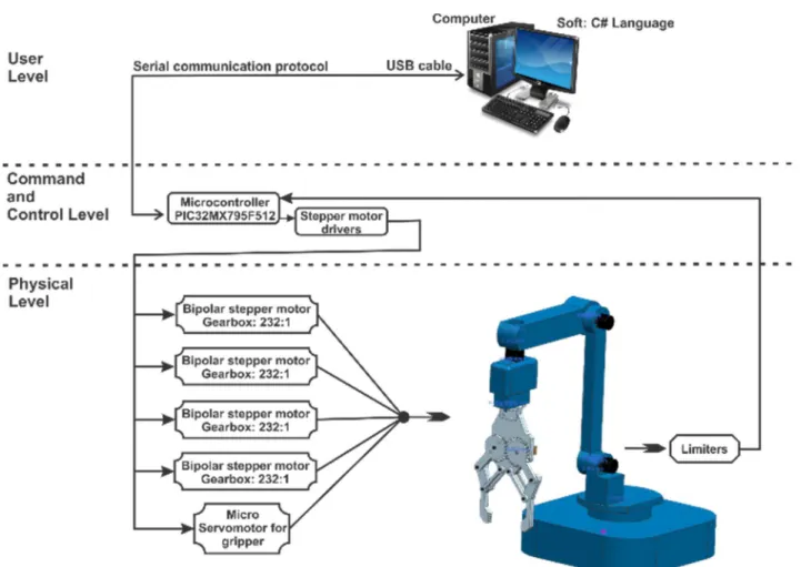
A schematic representation of the serial robot control and actuation system is presented in Figure 5.
The control system of the robot is structure on three levels:
• User Level;
• Command and Control Level;
• Physical Level;
Fig. 5 The control system of the serial robot User Level – integrates a computer with
Visual Studio C# programming environment. In
this programming environment the User
interface has been created. The communication between computer and microcontroller has been made via the serial communication protocol.
The next level, Command and Control
Level contains microcontroller board and the motor drivers.
- The development board with
microcontroller is called chipKIT Max32 (Figure 6) from Digilent, this development board uses an PIC32MX795F512L chip. It has 83 digital input/output pins, 16 analog inputs, 4 UARTs (hardware serial ports), 2 CAN controllers, an 80 MHz crystal oscillator, 512K Flash, 128K RAM, a USB
2 connection, a power jack and a reset button. On microcontroller are found program for motors and sensors. These programs are written in the programming environment called MPLAB, in AnsiC and Arduino programming language.
- “Big Easy driver” (Figure 7) has been used for the stepper motor driver. This motor stepper driver was designed by Brian Schmalz, and is a stepper motor driver board for bi-polar stepper motors up to a 2A/phase, based on the Allegro A4988 stepper driver chip. Each Big Easy Driver can drive up to a max of 2A per phase. It can take a maximum motor drive voltage of around 30V, includes on-board 5V/3.3V regulation, and a power supply is necessary for this stepper driver.
Fig. 7. 1. Big Easy Driver
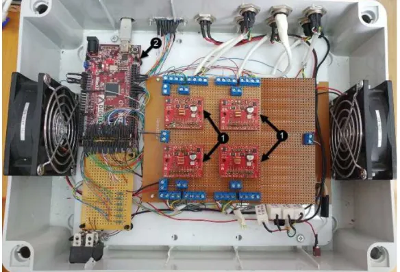
The physical structure of the command and control unit of the serial robot is presented in Figure 7. In this control unit we can see the stepper motor drivers (Figure 7, 1) and microcontroller board (Figure 7, 2).
Fig. 7.2 Physical structure of the control system Physical Level - contains three main parts:
- The mechanical structure of the serial robot;
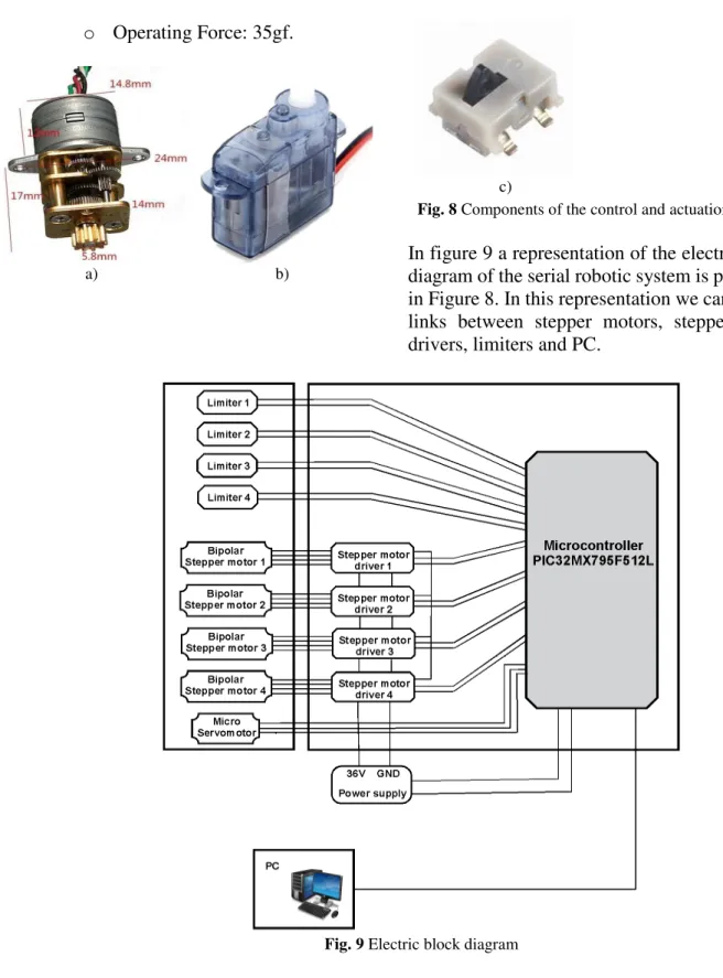
- The bipolar stepper motor (Figure 8a):
o Reduction ratio: 232:1;
o Voltage: 5V-12V DC;
o Phase resistance: 40 ohm;
o Size 15mm.
- Micro Servomotor 2.5 g (Figure 8b), this kind of motor does not need a driver for control:
o Operating Voltage: 4.8V~6V;
o Control System: Analog;
o Operating Angle: 120degree;
o Required Pulse: 900us-2100us;
o Weight: 2.5g;
o Dimensions: 19.4×8.5×16.5 mm.
- SMD micro-switches – to detect the reference position at the end of the stroke (Figure. 7c):
o Actuator Type: Angled Toggle
(Detector);
o Current Rating: 1mA (DC);
o Operating Force: 35gf.
a) b)
c)
Fig. 8 Components of the control and actuation system In figure 9 a representation of the electric block diagram of the serial robotic system is presented in Figure 8. In this representation we can see the links between stepper motors, stepper motor drivers, limiters and PC.
Fig. 9 Electric block diagram
4. THE USER INTERFACE
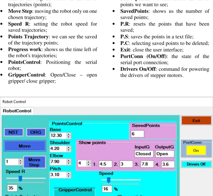
In order to able to interact with the robot, a simple user interface using well defined virtual buttons has been development, presented in Figure 10.
The interface has the following elements:
• NST: defining the zero point, which
performs the initialization of the motors position of the robotic system. By means of the microswitches mounted on the base and arm of the robot is ensured these zero positions;
• ORG: command for moving the robot in
• Move: moving the robot on the saved
trajectories (points);
• Move Step: moving the robot only on one
chosen trajectory;
• Speed R: setting the robot speed for
saved trajectories;
• Points Trajectory: we can see the saved
of the trajectory points;
• Progress work: shows us the time left of
the robot's trajectories;
• PointsControl: Positioning the serial
robot;
• GripperControl: Open/Close – open
gripper/ close gripper;
• Show points: we can choose the saved
points we want to see;
• SavedPoints: shows us the number of
saved points;
• P.R: resets the points that have been
saved;
• P.S: saves the points in a text file;
• P.C: selecting saved points to be deleted; • Exit: close the user interface;
• PortConn (On/Off): the state of the
serial port connection;
• Drivers On/Off: command for powering
the drivers of stepper motors.
Fig. 10 Control system – User Interface
Fig. 11 Use case diagram
In the UML diagram of the Usage Cases from Figure 11, we can see the commands which the user can give to via the user interface.
In the UML Activity Diagram (Figure 12) is represented the trajectory which the robot must accomplish.
A representation of the block software diagram is presented in Figure 13. This diagram is divided into two control system levels:
• PC level, this level includes the user
interface and controls the commands;
• Microcontroller level, here we find the
software to the hardware, drivers and stepper motor control unit with PIC32MX795F512 chip.
Fig. 13 Block software diagram
The two levels of the robot control are:
In terms of software the first level contains the man-machine interface; input data is introduced by the user. By the robot program, user commands are processed, analyzed and verified, then program computes the motion parameters and then are sent to the microcontroller.
In the last level electrical signals to control the motors are generated. Before the data input is sent to the motor stepper drivers, these are processed by the microcontroller. For stepper motor drivers, three signals are used:
the driver is activated with the enable signal;
for momentum to the execution of a step,
the step signal has been used;
with dir signal we define the sense of motor rotation.
Through output ports, the signal from the stepper motor drivers reaches to the stepper motors.
4.1 Performing the steps to control the robotic system via the user interface
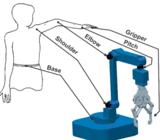
Fig. 14 Analogy between the human body and the robot
Via the following NumericUpDown fields the serial robot will be positioned:
• Base - the robot rotates around the base; • Shoulder - is rotate on the vertical axis; • Elbow - is rotate on the vertical axis; • Pitch - is rotate on the horizontal axis;
In GripperControl field we have two buttons:
• Open - button to open the gripper; • Close - button to close the gripper.
After the positioning is made, the first point will be saved by pressing the P.S button and in the Saved Points field we can see the total number of saved points. In Show points field we can choose the saved points we want to see, here we can see the point coordinates and gripper state. By pressing the “P.C” button, we can delete the saved points, and pressing the “P.R” button we will reset the saved points. After the points have been saved the robot's speed will be set via Speed R slider. The next step consists in pressing the “NST” and “ORG” buttons. After the robot has been initialized we'll be able to press on the “Move” button, and from this moment the robot will move on the saved trajectories. If we want to go only on one trajectory we will choose a single trajectory from the saved trajectories and we will press the “Move Step” button. On the user interface we can also see a progress bar indicating the state of the trajectories.
5. CONCLUSION
The paper presents the control and action of a serial robotic arm with four degrees of freedom.
This robot is equipped with a gripper which can catch objects. A detailed presentation of the user interface linked to the implemented control program has been also showed in this paper. Performed laboratory tests have validated the system performances.
ACKNOWLEDGEMENT
This paper was supported by the project „Inter-University Partnership for Excellence in Engineering - PARTING - project coordinated by the Technical University of Cluj-Napoca”
contract no. POSDRU/159/1.5/S/137516,
project cofounded by the European Social Fund through the Sectorial Operational Program Human Resources 2007-2013, financed by UEFISCDI.
REFERENCES
[1] P, Zoran., D, Vladimir., Comparison of the characteristics Between Serial and parallel robots, Acta Tehnica Corviniensis – Buletin of Engineering Tome VII [2014] Volume 1, ISSN: 2067 – 3809
[2] B, Torgny., Present and future robot control development- An industrial perspective, Elsevier, Annual Reviews in Control, Volume 31 (2007) pages: 69–79
[3] D, Claire., C, Stephane., G, Sebastien., F, Benoit., Robotics and Computer-Integrated Manufacturing, Robotics and Computer-Integrated Manufacturing 27, (2011), pages 881–888
[4] G, Ben., K. M., R. G., A kinematic analysis and evaluation of planar robots designed from optimally fault-tolerant Jacobins. IEEE Transactions on Robotics, Volume 30 (2014), pages: 516–524.
[5] A, Gómez., P, Lafuente., Design and construction of a didactic 3-dof parallel links robot station with a 1-dof gripper. Journal of Applied Research and Technology, Volume 12(3) (2014), pages: 435–443.
[6] M, Savioli., A, Jardini., R, Filho., Synthesis and Characterizations of Poly (Lactic Acid)
by Ring-Opening Polymerization for
[7] R, Drumright., P, ruber., D, Henton., Polylactic acid technology, Volume 12, Issue 23, 1 December 2000, Pages 1841-1846, ISSN: 09359648
[8]***,http://www.feetechrc.com/product/analo g-servo/super-micro-0-09sec60degree-0-6kg-cm-analog-servo-fs0205/
[9]***,www.robofun.ro/big-easy-driver?search=easy%20driver
[10]***,http://www.adelaida.ro/placa- dezvoltare-chipkit-max32-pic32-microchip.html
[11]***,www.optimusdigital.ro/ro/motoare- motoare-pas-cu-pas/2362-motor-pas-cu-pas-
cu-2-faze-de-15-mm-cu-reductor-de-metal.html?search_query=motoare+pas+cu+ pas&results=45
[12]***, www.digikey.com/product-detail/en/c-k/HDT0004/CKN9956CT-ND/2060727
[13] S, Patel., T, Sobh., Manipulator
performance measures – a comprehensive literature survey. J Intell Robotic Syst; 2014. doi: 10.1007/s10846-014-0024-y.
[14] M, Raghaven., B. Roth., Kinematic analysis of the 6R manipulator of general geometry. In: Proc fifth int symp on robotics research; 1990. pages: 263–9. ISBN:0-262-13253-2
[15] B., Gherman, D., Pisla, C., Vaida, N., Plitea, On workspace and accuracy evaluation of a parallel robot for needle placement procedures. In: Proceedings of the Romanian Academy, series A, 2016. Volume 17(4), pages: 344–351
[16] Y, Chen., G, Leitmann., Robust control for rigid serial manipulators: A general setting. In American Control Conference (Vol. 2, pp. 912–916). IEEE. ISBN: 0-7803-4530-4
[17] C, Kiang., A, Spowage., Review of control and sensor system of flexible manipulator. Journal of Intelligent and Robotic Systems, January 2015, Volume 77, Issue 1, pages: 187–213, Print ISSN 0921-0296
ACȚIONAREA ȘI CONTROLUL UNUI BRAȚ ROBOTIC SERIAL CU PATRU GRADE DE LIBERTATE
Rezumat: Lucrarea prezintă acționarea si controlul unui brat robotic serial. Acest sistem robotic are patru grade de libertate. Pe robotul serial este atasat un griper cu care se pot prinde diferite obiecte de dimensiuni mici. Robotul se controlează prin intermediul unei interfețe utilizator, iar pentru deplasarea robotului se fac traiectorii, pe urmă aceste traiectorii sunt scrise într-un fișier. Pentru repetarea traiectoriilor robotului, noi trebuie să citim fișierul cu traiectoriile salvate.