Corresponding Author: aliakbar mobasseri, Young researchers and elite club, Andimeshk branch, Islamic Azad University,
Optimization of Combined Layers Produced by the Ceramic/Composite and
ceramic/Aluminum Plates
1
Ali Akbar Mobasseri,
2Abdol Reza Ansari,
2Hamid Reza Zarei,
2Mohammad Sedighi,
3Fatemeh
Mobasseri
1
Young researchers and elite club, Andimeshk branch, Islamic Azad University, Andimeshk, Iran
2ShahidSattari Air University, Graduate Center, Tehran, Iran
3Sama technical vocational training college, Islamic Azad University, Kazeroon branch,
Kazeroon, Iran
Abstract: In this dissertation the high velocity impact behavior of the ceramic/composite and ceramic/Aluminum plates were investigated. With the use of finite element method the perforation and energy dissipation mechanisms of the mentioned plates were determined. The existing analytical model that is applied to find optimum ceramic/composite and ceramic/Aluminum plates was reviewed. With the use of optimization method the optimum plate which has maximum energy absorption capacity and minimum weight was determined. In this optimization process the responses of the plates were determined with the use of finite element method and the response surface method was applied to construct the approximate optimization functions and constrains. A genetic algorithm optimization method was applied to find the optimum thicknesses of ceramic/composite and ceramic/Aluminum layers, respectively. Finally, the presented optimum plate and the optimum solutions that have been extracted from analytical models were compared.
Key words: Projectile, Composite materials, Ceramic, Aluminum, High velocity impact, Optimization.
INTRODUCTION
Current statistics of the injuries caused by transportation has proved that passenger jet airplanes are among the safest transportation vehicles. However, the crashes that have happened in this area can't be ignored. One of the most common underlying reasons in aviation is the failure of jet engines. Total failure and partial destruction (breaking down of small parts) of main rotor and disks of such engines have led to air crashes.
Among the most disastrous crashes in this area, is the crash of DC-10 airplane in Ivan state of the U.S that resulted in the death of 103 people. Breaking down of small pieces of rotary disc and their impact to the hydraulic linkages was distinguished as the reason of this crash. Every year the world sees similar crashes and events, in which the main reason is the impact of separated parts of different sections of airplane to sensitive systems.Therefore, airplane markers put great emphasis on the protection of vital sections of airplane such as oxygen capsule, hydraulic, fuel and etc., which contain highly flammable material.
Thus, strength and impact problems of aviation structures have attracted the researchers' attention. Crashes due to malfunction of turbojet engines, has been identified as a common problem in federal aviation FAA, NASA and airplane industries (Witmer (Ed.), E.A., 1977; Sarkar, S., S.N. Atluri, 1995; Federal Aviation Administration, 1997; Mathis, J.A., 1997; Federal Aviation Administration, 1990) federal aviation association (FAA), has issued procedures, and failures that are caused because of separation of turbine engine stages, which result in crash of airplane. (Engine Containment, 1987)
The failure of rotary section, the separated parts of which has great power can pass the engine and reach the fuel tanks and hydraulic reservoirs, and lead to destructive damages to airplane and passengers. (Le, D.D., 1997) Also such malfunction, influence the operation of airplane in flight either directly or indirectly. (National Transportation Safety Board, 1996).
To prevent such problems, the sensitive sections of airplane must be protected against impacts using resistant materials. Considering the strength and lightness of composite materials, the use of them seems to be the appropriate choice in different parts of aircrafts. So, the strong versions of such materials can be used in order to prevent sensitive sections of aircraft.
Wang, B., G. Lu, 1996; Ben-Dor, G., et al., 2000; Jing Shi, Dana Grow, 2007; Ben-Dor, G., A. Dubinsky, T. Elperin, 2009).
MATERIAL AND METHODS
In 1978, Wilkins presented calculation methods in investigating fracture models in ceramics used in compound plates of ceramic and aluminum. In this method, ceramic has been employed as the front plate and aluminum has been used as back plate. (WILKINS, M.L., 1978)
In 1987, Myseless, studied penetration in ceramics and found out that the necessary energy for fracture ceramic, is a fraction of the total energy of the projectile. (Myseless, M., et al., 1987)
Tate presented a model about the penetration of projectiles in ceramic targets. According to which reformed equation of Bernoulli in fluids, is about the balance of pressure on the interface surface of target- projectile. In 1990 this model was employed by Rosenberg in impact of long rod projectiles, in ceramic targets. (Rosenberg, Z., I. Tsaliah, 1990)
In 1990, Woodward presented a one-dimensional model about penetration in ceramic-composite targets. This model considered the erosion of projectile and ceramic and presented a proper estimation of projectile velocity, reduced mass of that, and penetrability or impenetrability of projectile and target. (Woodward, R.L., 1990)
In 1998, Checron presented a completed and simple one-dimensional model from the ballistic of impact against ceramic composite. This model gives the residual velocity, residual mass, projectile velocity and strain histories of backup material. This model has been compared with ballistic test and numerical simulation and the results have shown great compatibility. (Checron Benlolo, I.S., et al., 1998)
Fellows in 1999 presented a model that predicated the penetration of projectile in semi-infinite ceramic targets. This model simplifies the study of material properties and the change of target making on penetration. The literature and theoretical decoration results have been investigated in two positions of long rod penetrate and spherical projectiles. A good agreement was seen between practice and theory. (Fellows, N.A., P.C. Bartan, 1999)
Lundlburg in 2000, investigated the critical impact velocity for the transition between interface defeat and normal penetration theoretically and experimentally. He established two models, which permit the determination of the surface load and the conditions for incipient and large-scale yield, respectively. (Lundburg, P., V. Renstrom, Lundburg, 2000)
Wen and He in 2007 conducted a theoretical study on the penetration of projectile in FRP layers. The formulations were based on the assumption that the deformation is localized and that the pressure offered by the laminate targets toresist the projectiles was velocity dependent which can be divided into two parts: a quasi-static part due to the elastic–plastic deformation of the laminate materials and adynamic part due to penetration velocity. Equations havebeen derived for the depth of penetration, residual velocity, and ballistic limit. (He, T., H.M. Wen, Y. Qin, 2007)
In 2008 Lee and colleagues conducted a numerical study on an armor which was made of 4 layers of metal, ceramic, metal and three layers composite using the NET3D software. (Lee, M., et al., 2008)
A great number of conducted studies have tried to optimize the compound armors, ceramic-composite. In addition, some studies have been done, in this area, to present analytical models. The model presented by Florence can be mentioned as an example.
In 1967, Florence in addition to investigating the penetration of projectile in compound targets of ceramic-composite, presented a model to estimate the velocity of ballistic limits. (Florence, A.L., 1969)
Hetherington in 1991 used the Florence model to improve a composite target. He considered the total thickness of target to be stable, but the density was not stable and his target was to maximize the ballistic velocity limit. (Hetherington, J.G., 1992)
Dor and colleagues in 2000 improved the Florence model and optimized a compound target model of a front plate model of ceramic and a back plate made of composite. They considered the surface density to be stable and made optimization with the minimum areal density with the velocity of presented ballistic limit. (Ben-Dor, G., et al., 2000)
Shi in 2007, discussed about the maximum impact velocity under constraint of the total thickness or the areal density of the armor. The design optimization of two-component armor system is viewed from a new perspective in which both. The total thickness and the areal density become the constraints. (Jing Shi, Dana Grow, 2007)
In 2009 Dor and colleagues improved a target made of ceramic-composite and considered the maximum ballistic velocity limit for areal density and presented thickness. (Ben-Dor, G., A. Dubinsky, T. Elperin, 2009).
a) In all articles, the basic model was presented by Florence model (WILKINS, M.L., 1978). In this model the projectile has been considered to be cylindrical that is not necessarily always the issue under analysis in these studies.
b) In all articles, except the article presented by Ben-Dor (2009) the required energy for fracture of ceramic has been ignored.
c) All of the presented models have tried to maximize armor resistance against penetration of projectile. Some of these studies have considered total density of construction as a constant value in optimizing equation[19, 20, 23, and 24]. Considering the high importance of weight in air structures in this article, in addition to investigating resistance against penetration of compound surfaces made of ceramic and composite material, these surfaces due to having maximum high resistance against penetration and minimum in weight have been optimizing. In the process of optimizing, resistance against penetration of compound surfaces is determined with finite element method and using genetic Algorithm of optimizing parameters. Here having numerically solved the problem of penetration, the response surface method has been used to determine the optimizing equation (the resistance of surfaces and weight) in terms of optimizing parameters.
Results:
The Numerical Modeling Of Penetration In Compound Surfaces:
1- The numerical modeling of penetration in ceramic-composite plates. 2- The numerical modeling of penetration in ceramic-aluminum plates.
1-The Numerical Modeling Of Penetration In Ceramic-Composite Plates:
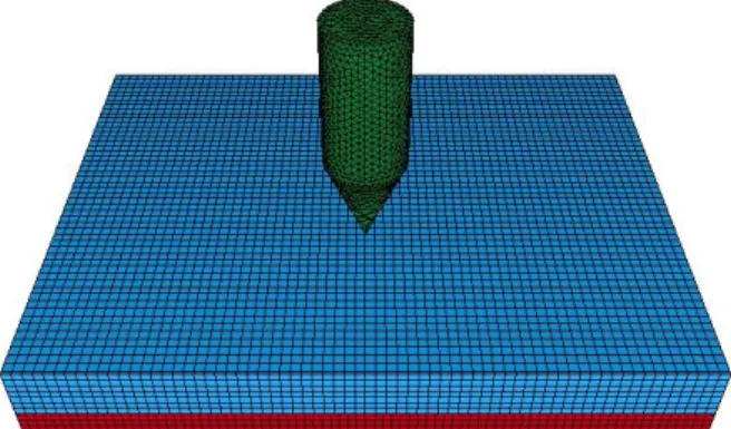
In numerical modeling, armor has been considered cubic rectangular with two layers, the front layer is boron carbide with Kevlar 49/Epoxy as the backup layer With dimensions of the plates 80 80 mm.Numerical simulation is done usingLS-Dyna-explicit software. The interface of the plate consists of a kind of silicone adhesive. The 450conical–cylindrical steel projectile has 30 mm length and 10 mm diameter.
In this simulation, the normal impact is considered with the velocity of 400 m/s. Figure (1)shows finite element model of target and projectile. Because of existing the large deformation and high strain rate condition, a three-dimensional solid-64 element and the strain rate dependent plasticity material are used for modeling. Both layers of material used in the armor system are modeled with eight-node uniform hexahedron solid elements whilst the projectile is modeled with six-node tetrahedron solid elements. Also an elastic-plastic model with the ability of considering failure in projectile. The contacts occurring during impact process are: (1) contact between projectile and ceramic, (2) contact between projectile and composite, and (3) contact between ceramic and composite.
The contact type that used is ‘‘eroding’ ’the eroding contact options are needed when the elements forming one or both exterior surfaces experience material failure during the contact. Contact is allowed to continue with the remaining interior elements. The eroding contact is used for contact between the projectile – boron carbide ceramic and the projectile – Kevlar/Epoxy composite.
The ‘‘Tied’’ contact is used for contact between ceramic and composites. The tied contact options actually ‘glue'. The contact nodes (ceramic) to the target surfaces (composites). The effect of tied contact is that the target surfaces can deform and the slave nodes are forced to follow that deformation. When defining tied contact, the body with the coarser mesh should always be defined as the target surface.
Fig. 1: modeling of projectile and target
Table 1: Mechanical properties of boron carbide (Shokrieh, M.M., G.H. Javadpour, 2008 )
Poisson’s ratio, ν Density, ρ
(kg/m3) Stiffness
E (GPa) Yield strength,
σy(GPa)
Tangent modulus, Et(GPa)
0.17 2500
440 15.8
0
Table 2: Mechanical properties of steel projectile (Shokrieh, M.M., G.H. Javadpour, 2008 )
Poisson’s ratio, ν Density, ρ
(kg/m3) Stiffness,
E (GPa) Yield strength
σy(GPa)
Tangent Modulus Et(GPa)
0.3 7890
202 1069
2
Table 3: Mechanical properties of Kevlar 49 composites (Engine Containment, 1987)
Poisson’s ratio, ν Stiffness,
E (GPa) Density, ρ
(kg/m3)
0.28 105
1382
Fig. 2: penetration of projectile in target in 0.05 ms
According to figure (3), the impact velocity of projectile in target is 400 m/s and residual velocity of projectile is 211 m/s.
Fig. 3: Projectile velocity variation curve versus time during impact on an armor
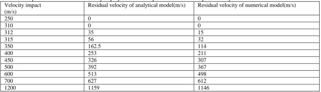
In table 4 the result of the residual velocity of projectile penetration of combined target with 11 different projectile velocities are given. In this simulation, the thickness of ceramic and composite were 6.9 and 3.1 respectively. As it can be seen in this table, the combined plate able to stop the projectiles with 310 m/s and in higher velocities the projectile penetrates in target.
Table 4: Comparison of the residual velocity of projectile in 10 impact with different impact velocity. Velocity impact
(m/s)
Residual velocity of analytical model(m/s) Residual velocity of numerical model(m/s)
250 0 0
310 0 0
312 35 15
315 56 32
350 162.5 114
400 253 211
450 326 307
500 392 367
600 513 498
700 627 612
The simple model presented in reference (Shokrieh, M.M., G.H. Javadpour, 2008) is used to evaluate the gained numerical result. In this analytical model, the energy equation (1) has been used. In this equation mp is the constant projectile mass, vs is the impact velocity, vr is the residual velocity, and v50 is the ballistic limit velocity.\
(1)
(2)
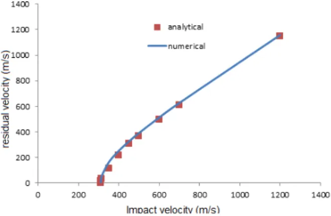
By considering 310 m/s as the ballistic limit velocity, according to the previous model, the results from analytical and numerical model are compared in figure (4) also the analytical and numerical results are compared in this figure. Here it can be seen that there is a good agreement between the numerical and analytical results. It is clear that the projectile stops at the target with a velocity of 310 m/s and in higher impact velocities, the residual velocity will be higher too. This shows the fact that at velocities of lower than ballistic limits, when the impact velocity increases, the absorption capability of energy increases too. Although at velocities higher than ballistic limits with the increase in impact velocity, the capacity of energy absorption has a considerable reduction. It should be noted that the validity of the simulation results are evaluated using the results presented by Shokrieh&Javadpour (Shokrieh, M.M., G.H. Javadpour, 2008). In this article the ballistic limit velocity for the similar plate to the one discussed in the present article has calculated to be 328 m/s that has a difference of about 5.5 percent with the presentballistic limit velocity.Considering the difference infinite elementmodellike size of used mesh in the present numerical simulation, these differences can be justified.
Fig. 4: Compare between analytical and numerical model
2-Numerical Modeling Of Penetration In Ceramic-Aluminum Plates:
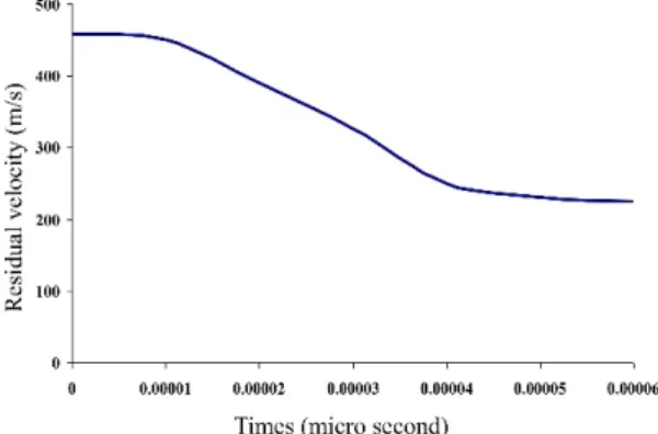
In this modeling, the compound plate of the upper plate of ceramic is made of alumina and the lower plate is made of aluminum2024. The numerical modeling is done using the finite element LS-Dyna. Here the projectile is modeled with half cylinder tip. The dimensions of half cylinder projectile are modeled according to figure (5) and the target panels with the dimensions of 250 250 mm and thickness of 10mm. In this simulation, the normal impact is considered with the impact velocity of 457 m/s. Both layers of material used in the armor system are modeled with eight-node uniform hexahedron solid elements. The eroding contact is used for contact between the projectile and target (Eroding-Node-to-Surface). Johnson-Cook's material model that is capable of applying the effect of strain rate is used for aluminum. Also an elastic-plastic model with the capability of considering the destruction in ceramic and projectile is used. The mechanical properties of materials in modeling projectile and target are derived from reference (Arias, A. et al., 2008). Figure(6) shows the compound surface finite element with thicknesses of 7.1mmand 2.9mm for ceramic and aluminum respectfully. Figure(7) shows the penetration of projectile in the mentioned surfaces in 0.6ms. The changes of projectile velocity are presented in figure(8), as it is clear from the figure the projectile is penetrated with a velocity of 457 m /sand the residual velocity of projectile is 225 m/s.
Fig. 6: Projectile Modeling and Target
Fig. 7: Influence of the projectile in the target in 0.6 microsecond.
Fig. 8: Graph of projectile velocity changes with time
In table 5the results of the residual velocity taken from simulation of the penetration of projectile in compound targets with 8 impact velocities.In these simulations, the thickness of ceramic and aluminum plates are 7.1mmand 2.9mm respectfully as it can be seen in this table the compound plate has been able to stop the projectiles up to a velocity of 250 m/s and in higher velocities, the projectile penetrates in target. The simple model presented in Borovicreference (Børvik, T., et al., 2009) is used to evaluate the numerical results. In this analytical model, the ballistic limit velocity and the residual velocity of projectile are presented as the equations (3) and (4).
(3)
(4)
In this equation σsis:
(5)
In equation (5), Y is the Yield strength and is the Yang model. In equation (3), L is the length of projectile, and the amount of l is its diameter. The amount of Kl is a number that is related to the geometrical parameters of projectile and vs is the impact velocity of projectile to the target.
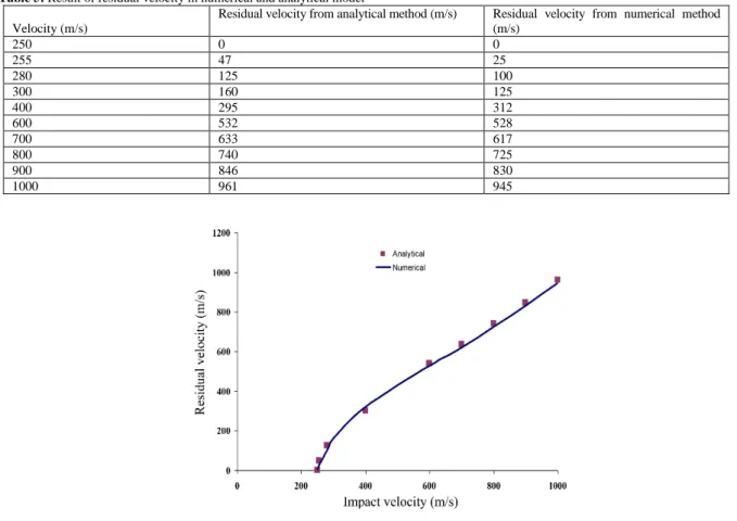
Also in figure(9),the numerical and analytical results are compared. Here it can be seen that there is a goodagreement between numerical and analytical results. What can be distinguished is that the projectile is stopped at the target with a velocity of 250m/s and in higher impact velocities; the residual velocity will be higher too. This shows that in velocities lower than ballistic limit, when the impact velocity increases, the energy absorption capability increases too. But in higher velocities higher than ballistic limit, with the increase of impact velocity, the absorption capability of the target reduces considerably. It should be pointed out that the validity of simulated models has been evaluated using the presented results by Borovic (Børvik, T., et al., 2009). In this article the analytical velocity limit for the plate similar to the one presented in this article is 276 m/s, which has a difference of 26 m/s with the gained limit ballistic. That the error possibility is 0.9 that can be justified according to the difference in the finite element model the sizes of the used meshes in the present numerical simulation.
Table 5: Result of residual velocity in numerical and analytical model
Residual velocity from numerical method (m/s)
Residual velocity from analytical method (m/s) Velocity (m/s)
0 0
250
25 47
255
100 125
280
125 160
300
312 295
400
528 532
600
617 633
700
725 740
800
830 846
900
945 961
1000
Fig. 9: Compare between analytical and numerical model
A Review Of The Methods Of Optimizing Of Compound Structures:
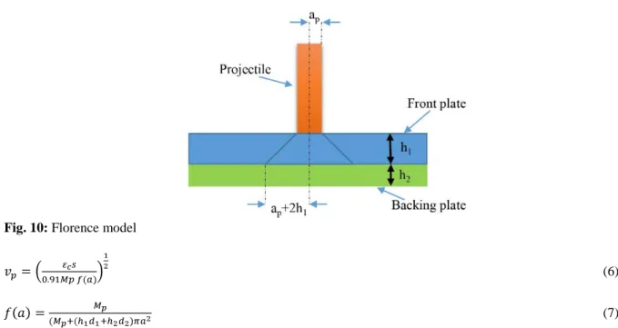
Recently most of the studies in this field have tried to optimize the compound armor of ceramic-composite. In this regard, so far some studies have been conducted to present analytical models. The model presented by Florence 1967 is a case in this point.
Fig. 10: Florence model
(6)
(7)
Where VP is ballistic limit velocity, a is a coefficient which is gained from laboratory information ,ɛcis breaking strain of backing plate.
Vp is the predicted value of V50, the ballistic limit velocity (m s- 1). (V50 is the velocityat which the projectile has a 50% chance of perforating the target at normal incidence.)
S = σc . h2
σc is the ultimate tensile strength of the backing plate (N m-2) Mp is the mass of the projectile (kg)
a = ap + 2h1 (m)
ap is the radius of the projectile's armour piercing core (m) h1 = ceramic plate thickness (m)
h2 = backing plate thickness (m) d1 = density of ceramic (kg m
-3 )
d2 = density of backing plate (kg m-3).= density of backing plate (kg m-3).
Hetherington in 1991 extended the Florence model and optimized a target, which was made of the front plate of Alumina and back plate of Aluminum he considered areal density, temperature parameters and total thickness of armor to be constant and reached the following equation. Hetherington reached equation (8) through improved Florence model.
(8)
Wang in 1996 used Florence model to improve compound surfaces as well he considered the total thickness of armour to be constant but did not consider the density constant. The purpose of optimizing was to maximize the ballistic limit. This equation is as follow.
(9)
T= the total thickness of armour. ap is the radius of the projectile. mp is the mass of projectile.
Ben-Dor and his colleagues in 2000 to some extent corrected Florence model to impact under the following condition:
1- Consider anormal impact. 2- The projectile is rigid.
4- Areal density of the armour is constant.
5- Hedid optimization for the least areal density with ballistic limit velocity.
They claimed that a proper thickness must be gained for ceramic to reach the least areal density andfinally they presented equation (11).
(10)
(11)
In this equation v0 is the ballistic limit velocity, ρ1andρ2 are areal density of front plate and back plate, respectively, ε2is the back plate fracture strain, σ2is the ultimate tensile strength of the back plate and α is the precision enhancement coefficient all of which have been gained in laboratory condition.
Jing Shi discussed about the maximum ballistic velocity under the range of areal density and total thickness. He calculated the total thickness range and density range he put them in optimizing the target. (Jing Shi, Dana Grow, 2007)
Ben-Dor and his colleagues in 2009, because of leaving maximum ballistic limit velocity, improved the compound armour and reached equation (12). (Ben-Dor, G., et al., 2009)
(12)
In this equation, b1 and b2are the thickness of front plate and back plate, respectively.γ2andγ1are the volume density of plates, A1and A2are the amount of the improved plate density.
In conditions that ceramic plate and back plate are made of alumina and aluminum alloy. Equation(13) can be stated as fallow.
(13)
Total thickness of armour: b=b1+b2
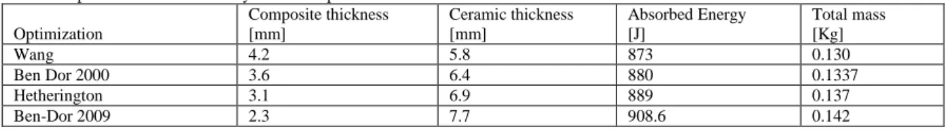
Using the presented equations, the improved thickness of compound plates composed of lower plate of composite and upper plate of ceramic and are presented in table 6, in which the total thickness of armour is 10mm. As can be seen, the improved surface gained from the above equation by Ben-Dorhas the maximum capacity of energy absorption, but the gained improved plate through the equation presented by Wang has the minimum weight.
The Limitations Of The Previous Studies About Optimizing:
Although it seems that comprehensive studies have been conducted in order to optimize the compound ceramic-composite targets, it is necessary to investigate in three more aspects;
A: In all articles the base model presented by Florence (1969) is used, in this model the geometrical form of projectile is considered to be cylinder that necessarily is not always so.
B:In all articles except the article by Ben Dor (2009), the necessary energy for breaking of ceramic has been ignored.
C: the presented models all try to maximize the strength against the penetration of compound plates. Some of these studies have entered the total weight of the structure as a fixed amount in optimization equations.
both models the optimized plate gained from the presented equation by Ben Dor (2009) has the highest energy absorption rate, but the optimized plate gained by Wang has the lowest weight.
Table 6: improved amounts for every one of the presented models
Total mass [Kg] Absorbed Energy [J] Ceramic thickness [mm] Composite thickness [mm] Optimization 0.130 873 5.8 4.2 Wang 0.1337 880 6.4 3.6
Ben Dor 2000
0.137 889 6.9 3.1 Hetherington 0.142 908.6 7.7 2.3 Ben-Dor 2009
The purpose of optimization is to gain the proper thickness for ceramic and composite which for the shield in additional to having the least areal density, can absorb the most amount of energy produced by the impact of projectile. Therefore, using numerical method, the reaction of surfaces with different thickness of layers has been calculated and sited in table 7 and 8. In these tables, the amount of absorbed energy in each layer and their total weight has been presented.
Here, the purpose is to find the optimized thickness of upper and lower surfaces, in such away so as to the target surface would have the minimum absorbed energy and minimum total weight. So in this process of optimization the density of surfaces, their absorbed energy, optimization equation and the thickness of layers have been considered as the optimization of parameters. Also the total thickness of armour is constant and equal to 10 mm.
In order to approximate determination of optimizing function (the plate strength and weight) in terms of optimizing parameters (the thickness of ceramic layer and composite) the response surface method was used. In this method, the approximate function is like equation (14).
(14)
In this equation, yi is the optimizing function, xiis optimizing parameters, β are the constants that should be determined, εi is the calculation error and N is the number of existent simulation.
1. Then using generic algorithm optimizing method
optimized thickness of layers has been calculated. Table 9 and 10 shows the result of optimizing.
Comparison of the result of table 7 with 9 and 8 with 10 shows that the present optimized plates, in addition to having acceptable energy absorption capability, they have less weight than previous optimized plate.
Table 7: Reaction of surfaces with different thickness of layers (ceramic-composite)
N u m be r Composite thickness [mm] Ceramic thickness [mm] Absorbed Energy [J] Total mass [Kg]
1 1 9 921.2 0.1528
2 2 8 897.8 0.1446
3 3 7 889 0.1375
4 4 6 860 0.1315
5 5 5 824 0.1240
6 6 4 827 0.1172
7 7 3 775 0.1095
8 8 2 709 0.1020
9 9 1 677 0.0955
Table 8: Reaction of surfaces with different thickness of layers (ceramic-aluminum alloy)
Total mass [Kg] Absorbed Energy [J]
aluminum thickness [mm] Ceramic thickness [mm]
Table 9: Optimize thickness for ceramic- composite Composite Thickness
[mm]
Ceramic thickness [mm]
released Energy [J]
Total mass [kg]
5.6 4.4 788 0.119
Table 10: Optimize thickness for ceramic-aluminum ceramic Thickness
[mm]
aluminum thickness [mm]
released Energy [J]
Total mass [kg]
7.1 2.9 7576 2.528
Discussions:
The results of the present study are as follow:
1- The study of all the present optimization models for compound plates shows that so far no method has tried to optimize this plate in order to have high strength against high penetration and low weight at the same time.
2- Using the finite element method and genetic algorithm as efficient and cheap instruments, the thickness of different layers of compound plate has been determined.
3- Comparing the present optimized plate with the results of previous methods, it can be concluded that the present optimized plate in addition to the capability of reasonable energy absorption, has a lower weight in comparison with the previous optimized plates.
REFERENCES
Arias, A. et al., 2008. Numerical simulations of impact behavior of thin steel plates subjected to cylindrical, conical and hemispherical non-deformable projectiles, Engineering Fracture Mechanics., 75: 1635-1656.
Ben-Dor, G., A. Dubinsky, T. Elperin, 2009. Improved Florence model and optimization of two-component Improved Florence model and optimization of two-component. Int.composite structures., 88: 158-165.
Ben-Dor, G., A. Dubinsky, T. Elperin, N. Frage, 2000. Optimization of two component ceramic armor for a given impact velocity. Int. Fracture Mechanics, 33: 185-190.
Børvik, T., M.J. Forrestal, O.S. Hopperstad, T.L. Warren, M. Langseth, 2009. Perforation of AA5083-H116 aluminium plates with conical-nose steel projectiles – Calculations.International Journal of Impact Engineering, 36: 426-437.
Checron Benlolo, I.S., V. SA`NCHEZ_GA`LVEZ, 1998. A new analytical model simulate impact on to ceramic Impact.Engng, 2(6): 461-471.
Federal Aviation Administration, 1990. Turbine engine rotor blade containment/durability, FAA Advisory Circular No.33-5.
Federal Aviation Administration, 1997. Design considerations for minimizing hazards caused by uncontained turbine engine and auxiliary power unit rotor failure, FAA Advisory Circular No. 20-128A, March 25.
Fellows, N.A., P.C. Bartan, 1999. Development of impact model for ceramic faced semi_infinite armour.Int,.J.ImpactEngng, 22: 793-811.
Florence, A.L., 1969. Interaction of projectiles and composite armour, Part II, Standford Part II, Standford Research Institute, Menlo Park, California, AMMRC-CR-69-15
He, T., H.M. Wen, Y. Qin, 2007. Penetration and perforation of FRP laminates struck transversely by conical-nosed projectiles.Int. Composite Structures, 81: 243-252.
Hetherington, J.G., 1992. the optimization of two component composite armours. Int.J. Impact Engng, pp: 409-414.
Jing Shi, Dana Grow, 2007. Effect of double constraints on the optimization of two-component armor systems. Int.composite structures., 79: 445-453.
Le, D.D., 1997. Evaluation of lightweight material concepts for aircraft turbine engine rotor failure protection, Federal Aviation Administration Report No. DOT/FAA/AR-96/110.
Lee, M., E.Y. Kim, Y.H. Yoo, 2008. Simulation of high velocity impact into ceramic composite systems using cohesive-law fracture model.Int. Impact Engineering, 35: 1636-1641.
Lundburg, P., V. Renstrom, Lundburg, 2000. Impact of metalic projectiles on ceramic targets: transition between interface defeat and penetration .Int.J. Impact Engng, 24: 259-275.
Mathis, J.A., 1997. Design procedures and analysis of turbine rotor fragment hazard containment, Federal Aviation Administration Report No. DOT/FAA/AR-96/121, March 1997.engine and auxiliary power unit rotor failure, FAA Advisory Circular No. 20-128A.
Myseless, M., W. Goldsmith. S.P. Virostek, S.A. Finnegan, 1987. Impact on ceramic targets, J.off applied mechanics v(58): 373-378.
Rosenberg, Z., I. Tsaliah, 1990. Applying Tate`s model for the interaction of long rod projectiles whit ceramic targets. Int.J.ImactEngng, 9(2): 247-251.
Sarkar, S., S.N. Atluri, 1995. Impact analysis of rotor fragments on aircraft engine containment structures, in: C.I. Chang,C.T. Sun (Eds.), Structural Integrity in Aging Aircraft, AD-Vol. 47, ASME, New York, pp: 87}97.
Shokrieh, M.M., G.H. Javadpour, 2008. Penetration analysis of a projectile in ceramic composite armor, Int.composite structures., 82: 269-276.
Society of Automotive Engineers Committee on Engine Containment, 1987. Report on aircraft engine containment, SAE AIR 4003.
Tate , A., 1967. A theory for the deceleration of long rods after impact., J.Mec. Phes.solids, 14: 378-399. Wang, B., G. Lu, 1996. On the optimisation of two-component plates against ballistic impact.Int. Materials Processing Technology, 57: 141-145.
WILKINS, M.L., 1978. Mechanics of penetration and perforation.Int.JENGNGsci .16: 793-807.
Witmer (Ed.), E.A., 1977. An assessment of technology for turbojet engine rotor failures, Proceedings of a WorkshopSponsored by NASA Lewis Research Center, MIT, March 29}31, NASA CP-2017.
Woodward, R.L., 1990. A simple one _ dimentional approach to modeling ceramic composite armour defeat. Int.J.Imact Engng, 9: 455-474.
![Table 9: Optimize thickness for ceramic- composite Composite Thickness [mm] Ceramic thickness [mm] released Energy [J] Total mass [kg] 5.6 4.4 788 0.119](https://thumb-us.123doks.com/thumbv2/123dok_us/7863341.2096267/11.892.112.779.115.236/optimize-thickness-composite-composite-thickness-ceramic-thickness-released.webp)
