System 800xA
Network
Configuration
System 800xA
Network
Configuration
NOTICE
This document contains information about one or more ABB products and may include a description of or a reference to one or more standards that may be generally relevant to the ABB products. The presence of any such description of a standard or reference to a standard is not a representation that all of the ABB products referenced in this document support all of the features of the described or ref-erenced standard. In order to determine the specific features supported by a particular ABB product, the reader should consult the product specifications for the particular ABB product.
ABB may have one or more patents or pending patent applications protecting the intellectual property in the ABB products described in this document.
The information in this document is subject to change without notice and should not be construed as a commitment by ABB. ABB assumes no responsibility for any errors that may appear in this document. Products described or referenced in this document are designed to be connected, and to communicate information and data via a secure network. It is the sole responsibility of the system/product owner to provide and continuously ensure a secure connection between the product and the system network and/or any other networks that may be connected.
The system/product owners must establish and maintain appropriate measures, including, but not lim-ited to, the installation of firewalls, application of authentication measures, encryption of data, installa-tion of antivirus programs, and so on, to protect the system, its products and networks, against security breaches, unauthorized access, interference, intrusion, leakage, and/or theft of data or information. ABB verifies the function of released products and updates. However system/product owners are ulti-mately responsible to ensure that any system update (including but not limited to code changes, con-figuration file changes, third-party software updates or patches, hardware change out, and so on) is compatible with the security measures implemented. The system/product owners must verify that the system and associated products function as expected in the environment they are deployed.
In no event shall ABB be liable for direct, indirect, special, incidental or consequential damages of any nature or kind arising from the use of this document, nor shall ABB be liable for incidental or conse-quential damages arising from use of any software or hardware described in this document.
This document and parts thereof must not be reproduced or copied without written permission from ABB, and the contents thereof must not be imparted to a third party nor used for any unauthorized pur-pose.
The software or hardware described in this document is furnished under a license and may be used, copied, or disclosed only in accordance with the terms of such license. This product meets the require-ments specified in EMC Directive 2004/108/EC and in Low Voltage Directive 2006/95/EC.
TRADEMARKS
All rights to copyrights, registered trademarks, and trademarks reside with their respective owners.
Copyright © 2003-2015 by ABB. All rights reserved.
Table of Contents
About this User Manual
Version Described in this User Manual ...14
User Manual Conventions ...14
Warning, Caution, Information, and Tip Icons ...14
Terminology...15
Released User Manuals and Release Notes...18
Section 1 - Introduction
Network Topologies...20Plant Network...21
Client/Server Network...21
Control Network...21
Fieldbus / Field Networks ...22
Network Areas...22
Combined Client/Server and Control Network ...23
Client/Server Network and Control Network on Separate Network Areas...24
Large Configuration with Control Network on Two Network Areas...25
Use of RNRP Backbone Areas in Configuration with Multiple Systems or Large Number of Network Areas ...26
Introduction to Network Redundancy ...28
Selecting IP Addresses ...29
Recommended IP Address Plan ...30
Network plan for field networks ...34
Introduction to Domain Controllers ...34
Table of Contents
Section 2 - Network Redundancy and Routing
RNRP ... 37
Network Areas... 38
Fault Handling within a Network Area... 40
Multiple Network Areas and RNRP Routers... 41
Local Network Areas ... 47
Building large networks by using Backbone Network Areas ... 47
RNRP Address Configuration: Implicit or Explicit ... 50
Using Explicit RNRP Configuration ... 51
First Project download when using other addresses than 172.16.x.x ... 53
Address Rules for Implicit RNRP Configuration ... 53
Using Network Area Numbers 32-63 ... 55
RNRP Configuration Parameters ... 56
Mixing Explicit and Implicit RNRP Configuration... 62
Interconnection of Network Areas over WAN ... 62
Interconnecting RNRP Network Areas via Standard IP Routers... 63
Use of Layer 2 VPN Solutions ... 69
Use of Layer 3 VPN Solutions ... 70
RNRP in a PC... 70
Configuring a Network Adapter ... 70
Configuring the Order of the Network Interfaces ... 71
Installing RNRP ... 72
Configuring RNRP for Windows... 73
Verify RNRP Connectivity ... 74
Configuring what Networks to Use ... 75
RNRP Network Loop Detection and Protection ... 76
Section 3 - Distributed System Topologies
Extend the 800xA Automation System Network ... 78Equal System Sections on Different Locations... 82
Security Considerations ... 83
Table of Contents
Multisystem Integration with redundancy...86
Asset Optimization...87
Section 4 - Field Networks
Selecting IP Addresses for Field Networks ...90Field Network Connectivity Servers ...92
Routing from the system network ...92
Network Redundancy ...93
Physical Field Networks ...94
Protocol specific documentation ...94
Section 5 - Network Security
Establish a Network Security Policy ...95The Onion Approach ...96
Firewalls ...98
Connections to 800xA Systems through Firewalls...100
Connect Inside-out Instead of Outside-in ...100
Network Address Translation in Firewalls...100
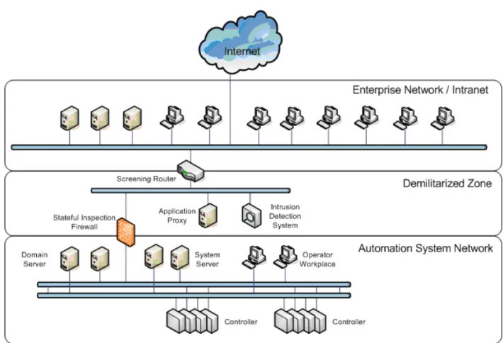
Single Firewall or a Demilitarized Zone ...103
Connecting a single Firewall to a Redundant Network...108
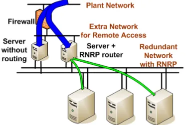
Using an Extra Network for Remote Access ...109
Redundant connection to external network ...110
Virtual Private Networks (VPN) for Secure Connections...110
Use cases for Connections through Firewalls...112
Remote/External Client ...113
Remote Windows Workplace ...114
Remote Usage of a Node on the System Network ...114
Information Manager Desktop Tools ...114
Remote Service with ABB Remote Access Platform ...115
Secure Connections for Remote Clients ...115
Remote Clients Connecting through a Demilitarized Zone ...116
Site to Site Connections via a Firewall...116
Table of Contents
Accessing OPC Data from External Network ... 118
Asset Optimization Integrations ... 120
Batch Integrations ... 121
Air Gap or Not, Data transfer To or From an 800xA System ... 121
Management of System Updates... 121
Using WSUS for Windows Updates ... 122
Managing Antivirus Updates ... 123
Other Services to be Used Through a Firewall ... 123
Summary of Ports to Open in Firewalls ... 124
AC 800M Network Storm Protection... 125
Section 6 - Domain Setup and Name handling
Node name handling and DNS... 127Choosing Names for Domains and PCs... 127
Allocating 800xA Systems to Domains... 128
Configuring Name Resolution and DNS... 129
Which Nodes use host names... 129
Location of Domain Controllers ... 130
Maintaining Redundant Domain Controllers ... 130
DcDiag: Domain Controller Diagnostics... 130
Backups of Domain Controllers ... 130
Recovering after a Crash of the First Installed Domain Controller ... 131
Time Synchronization in a Domain... 133
DNS Server Configuration ... 133
DNS Configuration in Each Node... 136
General DNS configuration in each node ... 136
RNRP’s host file service ... 139
Windows Workgroups instead of Windows Domain ... 142
Example of IP Addresses and DNS Configuration ... 142
Verifying Name Resolution functions ... 145
The RNRP monitor shows node names ... 145
ping -a instead of nslookup ... 145
Table of Contents
Section 7 - Time Synchronization
Recommended Time Synchronization Schemes ...148
Local Time Source ...148
External Time Source...152
Windows Time Instead of AfwTime ...155
Systems with More Than One Control Network...158
Time Synchronization with Multisystem Integration...159
Systems with MB 300 and 800xA for AC 800M ...162
MB 300 as Time Source for AC 800M ...166
Synchronization from the Client Server Network...169
Systems with AC 800M HI with Safe Peer-To-Peer ...172
Configure Time Synchronization in Controllers ...173
Time Synchronization Parameters for AC 800M ...173
Time Synchronization for MB 300 via CI855...175
Time Synchronization in Advant Master Controllers ...176
CNCP - Control Network Clock Protocol ...176
Forwarding of CNCP Between Network Areas ...178
SNTP - Simple Network Time Protocol ...178
SNTP Implementations ...178
Stratum ...179
SNTP Servers on a Redundant Network ...179
Routing SNTP Traffic ...180
Configuring SNTP...180
MB 300 Time Synchronization ...180
MMS Time Synchronization ...182
AfwTime Service...182
Configuration of the AfwTime Service...184
Configuring the AfwTime Server and the Server Group ...186
Configuring an AfwTime Client ...188
Time Synchronization for Connectivity Servers, Time Adaptors ...190
AC 800M Time Adaptor ...191
Table of Contents
Time Synchronization on the RTA Board ... 192
Time Sync with 800xA for Harmony ... 194
Time Sync with 800xA for Melody ... 195
Time Sync with 800xA for MOD 300 and 800xA for DCI ... 195
Windows Time Service (W32Time)... 196
Disable/Enable the Windows Time Service... 197
Configuring Time Zone and Daylight Saving Time Support... 198
Enable the SNTP Server, Disable SNTP Client in a PC ... 198
Configure Time Synchronization in a Dedicated Domain Controller ... 199
Comparison Between W32Time and the AfwTime Service... 200
Tuning the Synchronization Rate for W32Time ... 201
Setting the System Time... 201
Setting the Time with CNCP using the Control Builder M ... 204
Setting the time for the AfwTime Service ... 205
Adjust the Time in AC 800M via the Function Block SetDT... 206
Handling Time Changes when Using W32Time ... 207
Adjusting Time with 800xA for Melody or 800xA for Harmony ... 208
Fault Tracing Time Synchronization Problems... 208
Fault Tracing Time Sync in Controllers... 208
Fault Tracing SNTP ... 210
Fault Tracing AfwTime... 210
Section 8 - Ethernet and Network Equipment
Building a Physical Network... 213Hubs and Switches ... 214
Features in Switches... 215
Managed Switches ... 215
Basic Requirements on Switches ... 216
Necessary settings in Managed Switches ... 216
Features not Required in Switches... 217
Recommended Features in Switches ... 217
Ethernet Speed ... 217
Table of Contents
Physical Network Installation...218
Coexistence of Network Types...220
Reducing HW using Virtual LANs ...221
Ring Redundancy ...222
Using Rapid Spanning Tree ...224
Environmental Consideration...227
Connecting to a Redundant Network...229
Connecting a PC...230
Connecting a Controller without CPU Redundancy ...230
Connecting a Controller with CPU Redundancy ...231
Routers...232
Section 9 - Network Monitoring and Maintenance
Checking the Health of a 800xA System Network...233System Status Viewer ...234
Afw Service Connection Status Viewer ...237
Topology Designer / Topology Status Viewer ...238
Node Status Alarms ...239
Ping ...240
RNRP Network Monitor...240
RNRP Events in Controllers ...242
RNRP Fault Tracer/RNRP Utility ...242
Network Interface Supervision in a PC ...244
Network Interface Supervision in a Controller...245
Network Statistics from AC 800 M ...246
Monitoring MMS Communication...247
Using Network Management information...248
PC, Network and Software Monitoring...248
Network Management Tools from Switch Vendors ...250
Appendix A - Reference Details
IP Addresses ...251Table of Contents
Choosing Address Space ... 253
Using Implicit or Explicit RNRP Configuration ... 254
Suggested Configuration of RNRP and IP Addresses ... 255
IP Addresses for Redundant Controller Nodes... 256
Revision History
About this User Manual
This manual describes how to configure the 800xA Automation System Network, including the Client Server Network, the Control Network, and how to connect to a Plant Network. It generally does not cover fieldbuses.
The section about Network equipment however applies to Ethernet communication in general, which means that it also applies to Fieldbuses using Ethernet.
For the 800xA Automation System network the following main topics are covered:
• System Network topologies
• Network Redundancy
• Domain and DNS configuration
• Clock Synchronization
• Network installation and maintenance
• Network Security
Section 1, Introduction introduces the topics and the following sections describe them in more details.
For configuration of users, user groups, security settings, and group policies, please refer to System 800xA Administration and Security (3BSE037410*).
Any security measures described in this document, for example, for user access, password security, network security, firewalls, virus protection, and so on, represent possible steps that a user of an 800xA System may want to consider based on a risk assessment for a particular application and installation. This risk assessment, as well as the proper implementation, configuration, installation, operation, administration, and maintenance of all relevant security related equipment, software, and procedures, are the responsibility of the user of the 800xA System.
Version Described in this User Manual About this User Manual
This manual does not describe configuration of general purpose networks, such as an office or plant network, neither does it cover the situation where 800xA products are connected to a general purpose network.
Version Described in this User Manual
Unless otherwise noted, the versions of all 800xA Base System and Functional Area software described in this user manual are the latest release of 800xA 6.0.
User Manual Conventions
Microsoft Windows conventions as defined in the Microsoft Manual of Style are normally used for the standard presentation of material when entering text, key sequences, prompts, messages, menu items, screen elements, and so on.
Warning, Caution, Information, and Tip Icons
This manual includes Warning, Caution, and Information where appropriate to point out safety related or other important information. It also includes Tip to point out useful hints to the reader. The corresponding symbols should be interpreted as follows:
Electrical warning icon indicates the presence of a hazard which could result in electrical shock.
Warning icon indicates the presence of a hazard which could result in personal injury.
Caution icon indicates important information or warning related to the concept discussed in the text. It might indicate the presence of a hazard which could result in corruption of software or damage to equipment/property.
About this User Manual Terminology
Although Warning hazards are related to personal injury, and Caution hazards are associated with equipment or property damage, it should be understood that operation of damaged equipment could, under certain operational conditions, result in degraded process performance leading to personal injury or death. Therefore, fully comply with all Warning and Caution notices.
Terminology
A complete and comprehensive list of terms is included in System 800xA System Guide Functional Description (3BSE038018*). The listing includes terms and definitions that apply to the 800xA System where the usage is different from commonly accepted industry standard definitions and definitions given in standard dictionaries such as Webster’s Dictionary of Computer Terms.
Terms that uniquely apply to this manual are listed in the following table.
Tip icon indicates advice on, for example, how to design your project or how to use a certain function
Term/Acronym Description
AC 800M HI AC 800M High Integrity controller, certified for SIL 2 safety applications
Afw Services A system service for the 800xA core system
Client Client is a part of a software that subscribes data from a server.
Client/Server Network A client/server network is used for communication between servers, and between workplaces and servers. CNCP Control Network Clock Protocol. An ABB protocol for
synchronization of clocks in Controllers on the Control Network.
Connectivity Server A server that provides access to controllers and other sources for real-time data, historical data, and alarm and event data. A Connectivity Server runs services related to OPC/DA, OPC/AE, OPC/HDA.
Terminology About this User Manual
DHCP Dynamic Host Configuration Protocol
DNS Domain Name System
FSMO role Flexible Single Master Operation role. An Active Directory role which is not bound to a single Domain Controller
Hop count A measure of distance in a network. The hop count is equal to the number of routers that must be passed to reach a destination.
IAC Inter Application Communication (between AC 800M controllers)
IP Internet Protocol. A layer 3 protocol in the OSI model. IP address A 32-bit address assigned to each host/node connected
on the network.
IP address mask A 32-bit address mask used on an IP address to separate network from host identifier.
IPsec Internet Protocol Security
LAN Local Area Network
Mbps Mega Bit Per Second
MMS Manufacturing Message Specification. ISO standard for communication between controllers.
MPLS Multi Protocol Label Switching
Node A computer communicating on a network e.g. the Internet, Plant, Control or I/O network. Each node typically has a unique node address with a format depending on the network it is connected to. OSPF Open Shortest Path First
PC Computer running the Windows operating system
About this User Manual Terminology
Private IP addresses Blocks of IP address space that are reserved by the Internet Assigned Numbers Authority (IANA) for free use in private networks.
RMON Remote Monitoring. A standard for performing traffic analysis
RNRP Redundant Network Routing Protocol
Router A computer/device that forwards IP datagrams among the networks to which it is connected
SattBus An ABB fieldbus
Server A node that runs one or several Afw Services. It is the part of the software that supply data to a subscriber.
SIL Safety Integrity Level
SNMP Simple Network Management Protocol SNTP Simple Network Time Protocol
STP Shielded Twisted Pair cable
TCP Transmission Control Protocol. A Transport Layer
protocol in the Internet Protocol Suite
UDP User Datagram Protocol. A Transport Layer protocol in the Internet Protocol Suite
UTC Coordinated Universal Time UTP Un-shielded Twisted Pair cable
WAN Wide Area Network
VLAN Virtual Local Area Network WLAN Wireless Local Area Network VPN Virtual Private Network
VRRP Virtual Router Redundancy Protocol
Released User Manuals and Release Notes About this User Manual
Released User Manuals and Release Notes
A complete list of all User Manuals and Release Notes applicable to System 800xA is provided in System 800xA Released User Documents (3BUA000263*).
System 800xA Released User Documents (3BUA000263*) is updated each time a document is updated or a new document is released.
It is in pdf format and is provided in the following ways:
• Included on the documentation media provided with the system and published to ABB SolutionsBank when released as part of a major or minor release, Service Pack, Feature Pack, or System Revision.
• Published to ABB SolutionsBank when a User Manual or Release Note is updated in between any of the release cycles listed in the first bullet. A product bulletin is published each time System 800xA Released User Documents (3BUA000263*) is updated and published to ABB SolutionsBank.
Section 1 Introduction
This section introduces the main areas covered by this document: • Network Topologies, on page 20.
• Network Redundancy, on page 28. • Selection of IP addresses, on page 29. • Domain Controllers, on page 34.
• DNS configuration and Name handling, on page 35. The later sections will describe the different topics in detail.
Network Topologies Section 1 Introduction
Network Topologies
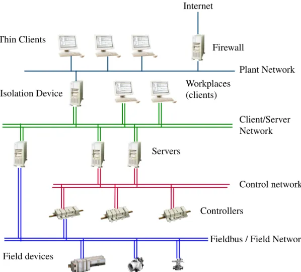
System communication in System 800xA is based on Ethernet and TCP/IP networks, which are functionally and, in most cases, also physically built in levels. The following figure shows the different levels in the network. Later sections will describe more about why the system should be separated into different network areas on different levels.
Figure 1. Network Topology: Plant-, Client/Server- and Control Network Plant Network Firewall
Internet
Controllers Isolation Device
Control network Thin Clients
Field devices
Fieldbus / Field Network Client/Server Network Workplaces
(clients)
Section 1 Introduction Plant Network
Plant Network
The Plant Network can be dedicated for process automation purposes or be a part of the plant intranet already available on a site.
Client/Server Network
The Client/Server network is used for communication between servers and between client Workplaces and servers.
The Client/Server Network is a trusted network zone that should be protected from unauthorized access. It is a private IP network that uses static addresses, see the recommendations on Selecting IP Addresses on page 29.
Methods for preventing unauthorized access to nodes on the Client Server Network include but are not limited to usage of IPSec and by separating the Client Server Network from other networks with firewalls. Protecting the Client Server Network with IPSec is described in System 800xA Installation and Upgrade Getting Started (2PAA111708*). Concepts for protecting the system with firewalls are described in
Section 5, Network Security.
The Client/Server Network supports network redundancy using the RNRP protocol and redundant Ethernet switches. Server and client PCs need additional network cards to adapt to redundant networks.
Control Network
The Control Network is used for communication between Controllers and between Controllers and Connectivity Servers. The Control Network is a trusted network zone that should be protected from unauthorized access. It is a private IP network that uses static addresses, see the recommendations on Selecting IP Addresses on page 29.
The maximum number of nodes on a Control Network area is 60 if any AC 800M with the processor modules PM85x or PM86x is connected to the network. If only PM89x is used the limit is 100.
The Control Network is based on Ethernet using the MMS protocol on top of a TCP/IP protocol stack, plus additional services for time distribution, redundancy
Due to security and performance reasons only IndustrialIT Certified products should be connected on the Client/Server Network.
Fieldbus / Field Networks Section 1 Introduction
management, etc. The Control Network supports network redundancy using the RNRP protocol and redundant Ethernet switches. Controllers connect to the control network via dual built-in network ports.
Fieldbus / Field Networks
System 800xA supports a large number of Fieldbuses. Some of these are based on Ethernet and are in this document referred to as Field Networks.
The specification for the specific Field Network describes the nodes to be connected to the network. This may include sensors, activators, IO systems, motor control systems, electrical protection relays, gateways and so on. These may be from ABB or 3rd party suppliers.
Out of the 800xA node types Controllers and Connectivity Servers connect to field networks.
It is recommended that separate networks be built for these protocols, i.e. avoid combining a Field Network with the Control Network. For more information see
Section 4, Field Networks.
Network Areas
The terms Client/Server Network and Control Network are used to describe the system functions performed by these networks. From an IP routing point of view the concept of Network Areas is used. A Network Area is a logically flat network that does not contain IP routers, i.e. routers can not forward traffic from one to another place on the same network area. In Figure 1, the Client/Server Network and the Control Network are different Network Areas with the Connectivity Servers potentially being used as IP routers. A Network Area may be redundant or non-redundant. A non-redundant Network Area maps to one IP subnet. A redundant Network Area maps to two IP subnets.
The Control Network should only be used for Controller traffic. Other traffic, especially broadcast or multicast traffic, may jeopardize Controller performance. Connect only IndustrialIT Certified products to the Control Network.
Section 1 Introduction Combined Client/Server and Control Network
Combined Client/Server and Control Network
In systems where the number of nodes is within the limit for the Control Network the Client/Server Network and the Control Network may be combined to one network.
Figure 2. Combined Control Network and Client/Server Network
Client/Server Network and Control Network on Separate Network Areas Section 1 Introduction
Client/Server Network and Control Network on Separate Network Areas
For medium to large systems it is recommended that the Control Network and Client/Server Network be separated into different Network Areas. The connection between the Network Areas is provided by Connectivity Servers using the RNRP routing protocol (Section 2, Network Redundancy and Routing). The two networks may be separated also for smaller systems. There are several reasons to separate the Control Network from the Client/Server Network:
• Fault isolation. An erroneous network segment on Client/Server Network will not affect nodes on the Control Network.
• Limitation of broadcast traffic. Broadcasts on Client/Server Network will not disturb the real-time traffic on the Control Network
• Traffic filtering. Undesired traffic can be blocked by the Connectivity Servers. The Control Network is more secure if it is isolated from the Client Server Network
Figure 3. Separated Client Server Network and Control Network
Control Network Client/Server Network Connectivity
Servers
Network Area 20 Network Area 1
Section 1 Introduction Large Configuration with Control Network on Two Network Areas
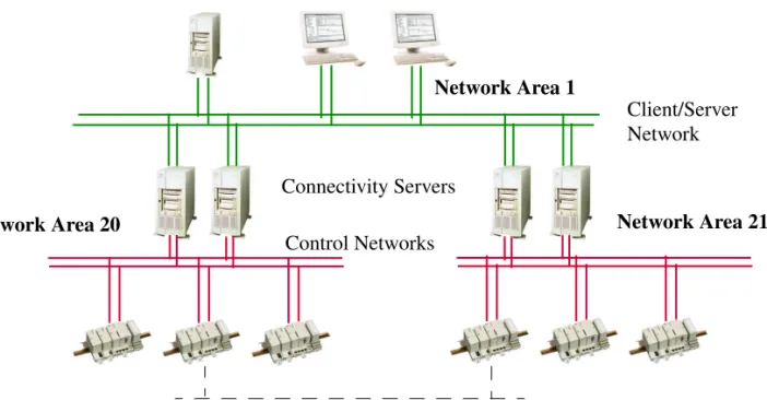
Large Configuration with Control Network on Two Network Areas
If the number of Control Network nodes is more than the limit for a Control Network area it is recommended to split the Control Network on two or more Network Areas.
For best performance the controller to controller communication should be kept within one Network Area.
Controllers on different Network Areas can communicate with MMS and IAC through the Client/Server Network, area 1 in the example above. The Connectivity Servers will act as routers, see Connectivity Servers as Routers on page 42.
Communication between controllers on different network areas can also be done using a protocol provided by any of the CI modules connected to AC 800M, e.g. MB 300 via CI855 or one of the fieldbuses. AC 800M, Communication Protocols (3BSE035982*) gives a complete overview of the options.
Figure 4. Separated Client Server Network and Multiple Control Networks Client/Server Network
Control Networks
Network Area 20 Network Area 21
Network for AC 800M peer-to-peer communication between Control network areas Network Area 1
Use of RNRP Backbone Areas in Configuration with Multiple Systems or Large Number of Network
Use of RNRP Backbone Areas in Configuration with Multiple Systems or
Large Number of Network Areas
Multiple 800xA Systems can be connected to one system network. In many cases it is beneficial to segment the system network so that one or a few network areas are allocated for each 800xA System.
When doing this it is normally recommended to restrict the amount of network status information being transferred between the network areas.
This can be done by using RNRP's concept of Backbone Network areas. If only standard RNRP network areas (that is not backbone areas) are used, all nodes will receive network status information about all other nodes on the whole system network. This causes extra unnecessary load in the nodes and AC 800 M controllers are limited to only handle network status from up to 15 remote areas. Using Backbone Areas it is possible to build a system network with up to 64 network areas where all nodes can communicate with each other but the detailed node status is only forwarded to a limited set of nodes.
Section 1 Introduction Use of RNRP Backbone Areas in Configuration with Multiple Systems or
For more information on Backbone Network areas, refer to Building large networks by using Backbone Network Areas on page 47.
Introduction to Network Redundancy Section 1 Introduction
Introduction to Network Redundancy
For high availability, all network devices (cables, switches, routers and network adapters) should be duplicated in physically separated network paths. The two network paths are named Primary Network and Secondary Network.
As long as the primary network paths are working, all process data is sent on that network. The secondary network normally carries no user traffic. This guarantees that network performance is not affected after a network fail over.
Both supervision of network paths and fail-over between Primary and Secondary networks are performed by RNRP.
In order to have a robust redundant system, it is very important to have continuous supervision of all network paths on a node-to-node basis, not only on individual Figure 6. Physical View of a full Redundant Network with Duplication of Switches, Cabling and Network Adapters
Primary Network
Section 1 Introduction Selecting IP Addresses
network devices. A detected network error results in fault annunciation. See Section 9, Network Monitoring and Maintenance.
For more information about redundancy, RNRP and network configurations, please read Section 2, Network Redundancy and Routing.
Section 4, Field Networks describes redundancy for Field networks not using RNRP.
Selecting IP Addresses
When planning a system the user must decide what IP addresses to use for all nodes in the system.
It is recommended that addresses be selected from a private address space. This has the following advantages:
• There is no requirement to apply to the licensing authorities for an IP address, i.e. it is easy to allocate a large IP address space especially in redundant network configurations.
• Some protection is gained against illegal access because private addresses are not permitted on the public Internet.
If it is not possible to use the recommended IP addresses, then read about RNRP addresses in RNRP Address Configuration: Implicit or Explicit on page 50 and in Appendix A How to Choose IP Addresses on page 253.
It is strongly recommended that addresses shown in the next chapter are used. This greatly simplifies the network configuration and reduces the probability for configuration errors.
Recommended IP Address Plan Section 1 Introduction
Recommended IP Address Plan
This section gives a recommendation on IP addresses that will work for most installations. If this suggestion is followed, the reader can disregard much of the details about RNRP configuration. Table 1 suggests which NetIDs1 to use.
Use the subnet mask 255.255.252.0 for all network interfaces. See also Network plan for field networks on page 34.
Table 1. Suggested NetIDs and Network Area Numbers
Network type NetIDs Network Areas
Plant Network 172.16.0.0 172.17.0.0
0
Client/Server Networks 172.16.x.0 172.17.x.0
where x=4,8,12 to 36 (steps of 4)
1-9
RTA Units PU410 and PU412
172.16.168.0 172.17.168.0
10
Control Networks 172.16.x.0 172.17.x.0
where x=80, 84, 88 to 124 (steps of 4) 20-31
1. NetID is the left most part of the IP address. See Appendix A, Reference Details
Do not connect more than 60 nodes to a Control Network Area where AC 800M controllers with processor modules PM85x or PM86x are used.
If only PM891 is used 100 nodes can be connected to the Control Network. If more than 32 network areas area used choose NetIDs 172.16.x.0 for network areas where you want to use implicit configuration. The other network areas need to use other NetIDs.
Section 1 Introduction Recommended IP Address Plan
Addresses recommended on the Client/Server/Control Network Area 1. Table 2. Suggested Addresses for Nodes on Network Area (1)
Nodes numberNode Addr on Primary Network Addr on Secondary Network
Domain and DNS servers
1-10 172.16.4. 1
-172.16.4.10
172.17.4. 1- 172.17.4.10
Aspect servers 11-20 172.16.4.11 -
172.16.4.20
172.17.4.11- 172.17.4.20
Connectivity servers 21-50 172.16.4.21 - 172.16.4.50
172.17.4.21 - 172.17.4.50
Application Servers IM, Batch, 3rd party
51-70 172.16.4.51-
172.16.4.70
172.17.4.51 - 172.17.4.70
Workplace Clients 71- 140 172.16.4.71 - 172.16.4.140
172.17.4.71 - 172.17.4.140
Routers and Firewalls 141 - 150 172.16.4.141 - 172.16.4.150
172.17.4.141 - 172.17.4.150
Controllers 151-220/255 172.16.4.151 -
172.16.4.220/255
172.17.4.151 - 172.17.4.220/255
Panel 800 (if used) (non redundant)
221-255 172.16.4.221 - 172.16.4.255
(not used)
Backup CPUs for Redundant Controllers
663-767 172.16.6.151 - 172.16.6.255
172.17.6.151 - 172.17.6.255
Switches, Gateways, Firewalls
(not RNRP addresses)
(501-511) (1013-1022) 172.16.5.245- 172.16.5.255 172.16.7.245- 172.16.7.254 172.17.5.245 - 172.17.5.255 172.17.7.245 - 172.17.7.254
Spare, Unused RNRP addresses
256-500
172.16.5.0-172.16.5.244
172.17.5.0-172.17.5.244
Spare, e.g. printers (not RNRP addresses)
(513(1)-662) (768-1012)
172.16.6.1(1) -172.16.6.150 172.16.7.0-172.16.7.244
172.17.6.1(1) -172.17.6.150 172.17.7.0-172.17.7.244
Recommended IP Address Plan Section 1 Introduction
The following addresses are recommended on the Control Network Area 20. Table 3. Suggested Addresses for nodes on Network Area (20)
Nodes numberNode Addr on Primary Network Addr on Secondary Network
Connectivity servers 21-50 172.16.80.21 - 172.16.80.50
172.17.80.21 - 172.17.80.50
Controllers 151-220/255 172.16.80.151 -
172.16.80.220/255
172.17.80.151 - 172.17.80.220/255
Panel 800 (if used) (non redundant)
221-255 172.16.80.221 - 172.16.80.255
(not used)
Backup CPUs for Redundant Controllers
663-767 172.16.82.151 - 172.16.82.255
172.17.82.151 - 172.17.82.255
Switches, Gateways, Firewalls
(not RNRP addresses)
(501-511) (1013-1022) 172.16.81.245- 172.16.81.255 172.16.83.245- 172.16.83.254 172.17.81.245 - 172.17.81.255 172.17.83.245 - 172.17.83.254
Spare, Unused RNRP addresses 256-500 172.16.81.0-172.16.81.244 172.17.81.0-172.17.81.244 Spare
(not RNRP addresses)
(512-662) (768-1012) 172.16.82.0-172.16.82.150 172.16.83.0-172.16.83.244 172.17.82.0-172.17.82.150 172.17.83.0-172.17.83.244
For controllers running SattBus on TCP/IP the HostID must be 2-127.
This means that the user needs to decide on a different node number allocation than Table 3. SattBus is described in the OnLine help for the Control Builder.
Section 1 Introduction Recommended IP Address Plan
The same information as in the previous tables, but generic for any Network Area with the area number as parameter ‘a’, is shown below (a = [0..31]).
The previous tables represent a=1 and a=20.
Table 4. Suggested Addresses for nodes on a Network Area (a)
Nodes numberNode Addr on Primary Network Addr on Secondary Network
Domain and DNS servers
1-10 172.16.4*a. 1 -172.16.4*a.10
172.17.4*a. 1- 172.17.4*a.10
Aspect servers 11-20 172.16.4*a.11 -
172.16.4*a.20
172.17.4*a.11- 172.17.4*a.20
Connectivity servers 21-50 172.16.4*a.21 - 172.16.4*a.50
172.17.4*a.21 - 172.17.4*a.50
Application Servers IM, Batch, 3rd party
51-70 172.16.4*a.51-
172.16.4*a.70
172.17.4*a.51 - 172.17.4*a.70
Workplace Clients 71- 150 172.16.4*a.71 -
172.16.4*a.150
172.17.4*a.71 - 172.17.4*a.150
Controllers 151-220/255 172.16.4*a.151 -
172.16.4*a.220/255
172.17.4*a.151 - 172.17.4*a.220/255
Panel 800 (if used) (non redundant)
221-255 172.16.4*a.221 - 172.16.4*a.255
(not used)
Backup CPUs for Redundant Controllers
663-767 172.16.4*a+2.151 - 172.16.4*a+2.255
172.17.4*a+2.151 - 172.17.4*a+2.255
Switches, Gateways, Firewalls
(not RNRP addresses)
(501-511) (1013-1022) 172.16.4*a+1.245- 172.16.4*a+1.255 172.16.4*a+3.245- 172.16.4*a+3.254 172.17.4*a+1.245 - 172.17.4*a+1.255 172.17.4*a+3.245 - 172.17.4*a+3.254
Spare, Unused RNRP addresses 256-500 172.16.4*a+1.0-172.16.4*a+1.244 172.17.4*a+1.0-172.17.4*a+1.244 Spare
(not RNRP addresses)
(513-662) (768-1012) 172.16.4*a+2.1-172.16.4*a+2.150 172.16.4*a 3.0-172.16.4*a+3.244 172.17.4*a+2.1-172.17.4*a+2.150 172.17.4*a+3.0-172.17.4*a+3.244
Network plan for field networks Section 1 Introduction
Network plan for field networks
In addition to the protocols on the System Network an 800xA system may use several other protocols based on Ethernet and TCP/IP, e.g. FOUNDATION Fieldbus, Modbus TCP, IEC 61850 or PROFINET. The system planning needs to include a plan for the networks used for these protocols including for example the addresses ranges to use. Section 4, Field Networks includes more information on what to consider.
Introduction to Domain Controllers
A domain is a group of nodes that are part of a network and share a common directory database.
A domain defines a scope or unit of policy. A Group Policy object establishes how domain resources can be accessed, configured, and used. These policies are applied only within the domain and not across domains. Applying a Group Policy object to the domain consolidates resource and security management.
A Domain Controller contains matching copies of the user accounts in a given domain. It is used to store and manage information about user credentials and access rights, both for humans and for the system. The Domain Controller provides the Active Directory service that manages user access to a network, which includes user logon, authentication, and access to the directory and shared resources.
Every domain must have at least one Domain Controller. To improve the availability of the system a domain may have multiple Domain Controllers to support the handling of logon requests and directory updates.
The domains are stored in the Active Directory. Administration of Domain Controllers to great extent means administration of the Active Directory. Use Windows Server 2012 R2 on all Domain Controllers in the same domain.
Single node systems, i.e. systems with only one PC, and small systems that use Windows Workgroups do not need Domain Controllers.
Section 1 Introduction Introduction to DNS, Name and Address resolution
Introduction to DNS, Name and Address resolution
DNS (Domain Name System) is a hierarchical name service for domains and IP addresses. The DNS service enables client nodes on your network to register and resolve DNS domain names and to find Domain Controller services.
DNS can be used for finding the IP address of a node which is only known by name (address resolution) and for finding the name of a node which is known by IP address (name resolution).
DNS can also be used for finding Domain Controller services, i.e. which node runs a certain service for the Domain.
In System 800xA 6.0, DNS is used for locating domain controller services. Name and address resolution is performed using hosts files that are updated by RNRP. 800xA applications that identify other nodes by name, i.e. not only by IP Address, use the information from the hosts file to find the corresponding IP address. Normally the primary (DNS) server is run on the same node as the Domain
controller. With multiple Domain Controllers in a system the DNS server functions are also distributed. This also improves the availability of the DNS.
Configuring the DNS functions in a system comprises:
• Configuring the DNS server on the Domain Controller(s).
• Configuring names and IP addresses, for nodes that will be possible to identify by name, in the DNS database.
• Configuring knowledge of the domain and the DNS server(s) in each node that uses DNS.
• Configuring knowledge of the Domain Controllers.
Further information about DNS can be found in the On-line help for DNS in Windows Server, the help file dnsconcepts.chm and in the resource kits in MSDN.
Section 2 Network Redundancy and Routing
This section describes the Network Redundancy based on RNRP (Redundant Network Routing Protocol). The main areas covered are:
• the concepts of the RNRP protocol
• how to build different network structures
• how to choose addresses
• how to configure RNRP in nodes; PCs and Controllers
RNRP
RNRP is an IPv4 routing protocol developed by ABB. It is specially designed for use in automation networks with limited topology but with high demands on network availability. RNRP provides the following features:
• Network redundancy
The protocol supports redundant physical networks, full redundancy including network interface boards, between end nodes. Routing messages are
periodically sent as multicast on all networks. If a network error occurs, RNRP updates the IP Routing Table of each affected node with a replacement network path within the “RNRP send period”, a configurable parameter (default=1s).
• Routing between network areas
IP routes to all neighbor nodes and subnetworks are automatically maintained in the IP Routing Table in every node. A node with RNRP can act as an IP router and forward messages on best path to destination nodes.
• Node and network supervision
RNRP quickly detects if a node or remote network is down and sends this information to applications that subscribe to RNRP status. This information is used to detect if a redundant server is down and whether a new server can be connected.
Network Areas Section 2 Network Redundancy and Routing
The RNRP redundancy concept works with standard network devices (hubs, switches or bridges) and no special functionality is required from the network interface cards (NICs).
The protocol gives high flexibility to integrate networks with different types of data links like PPP and Ethernet. The routing update period can be configured to fit on very slow serial links as well as on high speed networks mixed in the same Control Network.
Network Areas
A network that uses RNRP is built up by one or more Network Areas. A Network Area is a logically flat network structure without routers. Routers are not allowed within a Network Area.
A Network Area with redundancy contains two independent IP networks with equal capacity. The individual networks within a Network Area are assigned
Path Numbers.
The primary network has Path Number = 0 and the secondary network has Path Number = 1.
IP routing works for Unicast communication (node to node), not for Multicast or Broadcast. This means that RNRP does NOT provide redundancy or routing for Multicast or Broadcast communication.
Applications that use Multicast or Broadcast must take care of the network redundancy themselves, if desired communication between different network areas.
All RNRP versions used in previous system versions of the 800xA System are compatible with each other.
Section 2 Network Redundancy and Routing Network Areas
A node is identified in RNRP by:
• Network area number (0 - 63)
• Node number (1 - 500)
The path number is a parameter on each network interface (see RNRP Address Configuration: Implicit or Explicit on page 50).
In case of error on the primary network, the Redundant Network Routing Protocol (RNRP) redirects traffic over to the secondary network (the backup network) without involving any application program.
Nodes with redundant interfaces and nodes with a single interface can be mixed on the same Network Area. A node with only one interface must only be connected to the primary network.
Figure 7. A Network Consisting of one Network Area
Each path on a Network Area corresponds to one IP subnet. The NetID is the same for all interfaces on the same Path. (see IP Addresses on page 251)
Applications communicating with nodes that run RNRP shall always address the nodes on the primary network (path 0).
153 152
151 Primary Network
Path Number = 0
Secondary Network Path Number = 1
Node Numbers 21
Fault Handling within a Network Area Section 2 Network Redundancy and Routing
Fault Handling within a Network Area
Within a Network Area RNRP can handle single network errors in all node-to-node connections. In the example below, node A has an error on the connection to the primary network and node B an error on the connection to the secondary network.
In this example communication between node A and node B is not possible but all other peer communication will work.
Node A can communicate over secondary network with nodes C, D and E. Node B can communicate over primary network with nodes C, D and E. Nodes C, D and E are fully redundant to each other.
Network Fail Over Time
The time required for RNRP to redirect traffic from a faulty path to a good path is the same as the configured RNRP parameter Send Period, see Table 5 on page 57
(normally 1s).
Figure 8. A Fault handling in one Network Area
E B A
C D
X
X
Network Errors Connection!
Section 2 Network Redundancy and Routing Multiple Network Areas and RNRP Routers
Data Recover Time
The application data recover time is not the same as the network fail over time. A TCP application is not recovered until TCP has retransmitted lost data.
TCP continuously adjusts its retransmit time after transmission delays and repeated network errors. Standard TCP has a minimum value for retransmission of one second. This means that even if network fail over occur instantly, application data is not recovered until one second has elapsed. The default value of the RNRP
parameter Send Period has been set up to reflect this limitation.
Node Down Notification
A single lost message does not cause a Node down event. The time until a Node down event is generated is configured by the parameter MaxLostMessages (see Table 5 on page 57).
Time until node down event = (MaxLostMessages + 1) * SourceSendPeriod (normally (3+1)*1=4s).
Multiple Network Areas and RNRP Routers
There are a number of reasons why a network should be divided into Network Areas (subnetworks):
• Fault isolation. An erroneous network segment (bad cable, Ethernet switch or interface card) can not affect nodes on an other Network Areas.
• Traffic filtering. Undesired traffic can be blocked by a router if filter software is installed. This is true for a Windows Server node.
• Limitation of broadcast traffic. A router does normally not forward broadcast and multicast messages.
• The network is distributed over large distances using link protocols with different network characteristics. PPP is one example.
• The IP routing resources (Routing table, ARP table or CPU power etc.) in a single node are not large enough to handle a large number of nodes on the same Network Area.
Multiple Network Areas and RNRP Routers Section 2 Network Redundancy and Routing
For best performance the network designer should try to keep the time-critical traffic within the same Network Area. The time to change router node is always greater than the time to change path within the Network Area.
The Network Areas are interconnected by RNRP routers. A node with RNRP and connections to more than one network area can act as an RNRP router. In a PC additionally the flag “Enable TCP/IP forwarding” has to be set to 1 (see Table 5 on page page 57).
Limit the number of hops
A message between two nodes can be forwarded via several network areas. The number of routers it goes through is described by the term “hop count”. Network topologies with many hops must normally be avoided. The reason is that a large hop count increases the probability for undesired behavior such as routing loops and slow response time due to delayed updates from distant routers. The default max number of hops is 3. The maximum value is 5.
Limit the number of network areas
An RNRP network can consist of 64 network areas. Windows nodes can handle up to 64 network areas but Controllers can only handle up to 15 remote areas that are reached via routers, in addition to the areas (1 or 2) that the controller are directly connected to. A node for which the “max number of remote areas” is exceeded will not get routing entries for all network areas. This means that it will be unable to communicate with some nodes on the network, and it can not be predicted which nodes this is. To avoid this problem it must be made sure that, for all nodes the number of network areas that are within “max number of hops” does not exceed “max number of remote areas”.
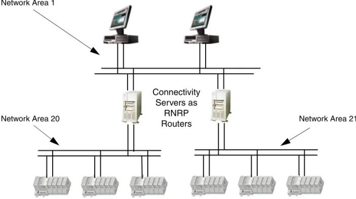
Connectivity Servers as Routers
In systems where the Control Network and the Client Server network are separated, the network is built up by different network areas. The connectivity servers that are connected to both networks, as in Figure 9, will work as RNRP routers provided that IP forwarding is enabled (see above). This makes it possible for all nodes on the Client Server network to communicate with all the Controllers on the Control Network. This is used by the Control Builder in an Engineering Client when it
Section 2 Network Redundancy and Routing Multiple Network Areas and RNRP Routers
communicates with the Controllers. The routing through the Connectivity Servers is also needed for the network alarm handling to work properly, see Node Status Alarms on page 239.
Controllers as Routers
The AC 800M controller can be used as router between non-redundant networks. There is no parameter to enable the routing capability. It is always enabled when RNRP is used and the controller is connected to two different network areas.
The function “Show Remote Systems” in the Control Builder and the OPC server uses broadcasting and does therefore not work through routers. The IP addresses of the controllers have to be known and entered manually when the networks are separated.
Figure 9. Network with Three Network Areas and Connectivity Servers as Routers
It is not possible to use two AC 800M Controllers to achieve a redundant connection between two redundant networks. For this 4 network interfaces per router is needed. This is described in Figure 11 on page 46.
Network Area 21 Network Area 1
Network Area 20
Connectivity Servers as
RNRP Routers
Multiple Network Areas and RNRP Routers Section 2 Network Redundancy and Routing
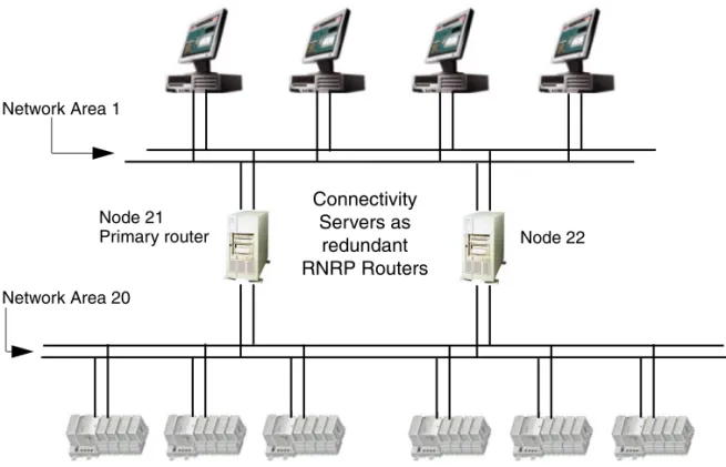
Redundant Connectivity Servers/Routers
A Connectivity Server (router node) can be a single point of failure. The RNRP protocol allows redundant router nodes between Network Areas. In the
configuration below RNRP selects the router with lowest node number as the active router node. If this node fails the RNRP protocol selects the other router as active.
In cases where multiple routes exist to a remote Network Area, the router that has the highest number of reachable nodes is selected as primary. If all routers have an equal number of reachable nodes then the router with the shortest distance (hop count) is selected as primary. If routers have equal distance then the intermediate network with lowest Network Area number is selected as the primary.
The network engineer should recognize that if serial links are used within the Control Network, throughput will be very low as compared to Ethernet alone. Figure 10. Two Network Areas with Redundant Connectivity Servers as Routers
Node 22 Node 21
Network Area 20 Network Area 1
Primary router
Connectivity Servers as
redundant RNRP Routers
Section 2 Network Redundancy and Routing Multiple Network Areas and RNRP Routers
In mixed configurations, it is recommended to put low Network Area numbers on the high capacity networks and high numbers on slow networks.
Default Gateway Routing for Nodes without RNRP
If nodes that do not support RNRP are connected to the control network, e.g. managed switches or time servers, and these nodes need to be accessed (by nodes that use RNRP) via the RNRP routers the necessary routing information can not be built up by RNRP. One way to solve this is to enter the primary Control Network address of the primary connectivity server as “Default Gateway” in these nodes to inform them about how to reach the Client Server network.
Routing between Control Networks
Controllers on Control Network areas can communicate with each other if the Connectivity servers work as routers as in Figure 9 on page 43. If it is desired that controller-to-controller communication is independent from the operation of the Connectivity servers and/or from the Client Server network it is possible to build a network where control networks are directly connected via dedicated routers.
Figure 11 shows two control network areas that are connected via a redundant pair A good rule to follow during network configuration is to make sure that all alternative routes to destination nodes have equal distance (hop count).
A network error should not cause redirection to a route with a greater distance. By following this rule, a network error will not change the node-to-node response time and no node will receive unpredictable loads from transit traffic.
An RNRP router has several advantages compared to a standard IP router: • No manual routing configuration is needed.
The routing information about all nodes and networks is spread automatically.
• The routers can be redundant.
It is not possible to avoid a single point of failure when connecting two redundant RNRP network areas with a pair of standard IP routers. To do this two RNRP routers with 4 network ports each are needed, see
Figure 10 on page 44 and Figure 11 on page 46.
Such a router can only be built using a PC with 4 network interfaces.
It is not possible to achieve the same functionality with two routers with two ports each.
Multiple Network Areas and RNRP Routers Section 2 Network Redundancy and Routing
of dedicated routers.
Special Routing Consideration
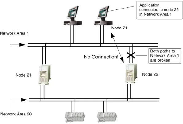
A message can only be received on the Network Area on which the message’s destination address belongs. Even if the message destination node is connected to multiple Network Areas and an alternative route exists through one of these other Network Areas, the protocol will not reroute to reach the destination node if the first Network Area breaks down.
Figure 12 on page 47 shows an example with an application in node 71 that has a session to target node 22 in Network Area 1. If node 22 loses both paths (double fault) on Network Area 1, then the application will lose the current connection even if it in theory is possible to route via Node 21 to Node 22 on Area 20.
Figure 11. Redundant RNRP routers for Controller-to-Controller communication
Network Area 21 Network Area 20
Connections to the Client Server Network. Not used for Controller-to-Controller Communication Redundant RNRP routers.
Dedicated for Controller-to-Controller
Section 2 Network Redundancy and Routing Local Network Areas
Local Network Areas
The RNRP protocol permits Network Areas to be declared as “Local”. A Local Network Area does not distribute information about own networks and nodes to adjacent Network Areas. Traffic from other Network Areas can not be routed over this local Network Area. Only nodes directly connected to a Local Network Area can use it. In this way, nodes within the Control Network can use dedicated networks without risking being overloaded by transit traffic.
Building large networks by using Backbone Network Areas
RNRP normally gives both redundancy and supervision between all nodes in the whole network. These features lead to some of the size restrictions for an RNRP network, for example the number of network areas.
Figure 12. A Network Connection is lost if all Paths to a Node in the Destination Network Area are Down
X
Network Area 1
Network Area 20
Node 71
Node 22 Node 21
Application
connected to node 22 in Network Area 1
Both paths to Network Area 1 are broken
Building large networks by using Backbone Network Areas Section 2 Network Redundancy and
If node to node supervision (fast detecting node up/node down) is not necessary between nodes in all different areas it is possible to build a large network by using a “Backbone Network Area” to interconnect up to 64 Network Areas.
A Backbone Network Area is similar to the Local Area with the difference that routing information can be received from neighbor areas but no routing information is sent out to standard neighbor areas. A node connected in the Backbone area receives all network information from all network areas (except local areas). A node in a standard Network Area does not get any network information about nodes and networks in the Backbone Area or other Network Areas. This means that those network areas do not occupy any network resources in the nodes in the standard network areas so when deciding the values for the parameters Number of remote network areas and Max number of hops (see Table 5 on page 57) the Backbone Network Areas and areas beyond these do not need to be considered.
In Figure 13 the function of the Backbone area means that (not all relations are mentioned): • A nodes get supervision information about each other.
• B nodes get supervision information about each other. • D nodes get supervision information about A, B and C nodes
• A and B nodes do not get supervision information about C and D-nodes • Communication between A, B and C nodes is possible via Default Gateway
(non redundant) or via External Network Service (redundant), see below. Figure 13. Using a Backbone area
Section 2 Network Redundancy and Routing Building large networks by using Backbone Network
Routing to or via a Backbone Area
Nodes in a Standard Network Area that need to communicate with nodes in a Backbone Area or an area beyond the Backbone area can configure the RNRP router connected to the Backbone area to be their Default Gateway.
If this communication needs to be redundant the parameters for External Network Service (see Table 5 on page 57) shall be used to refer to the router connected to the Backbone area. Use the primary address of one of the routers and the secondary address of the other router.
Example of setup required for nodes on Standard Network Areas in Figure 13 to communicate with A, B, C, D over Backbone Network Area.
If the routers R1 and R2 have the addresses 172.16.4.23 and 172.16.4.24 on the Standard Network area (down side interfaces) then these are the addresses to enter as the Router 1 and 2 addr to External Network in A-Nodes(A3/A4/A5) having direct connection to R1 and R2. A-Nodes below A3 and A4 sets Router 1 and 2 with addresses to A3 and A4.
If R3 and R4 have the addresses 172.16.8.23 and 172.16.8.24 on the Standard Network area then these are the addresses to enter as the Router 1 and 2 addr to External Network in Nodes having direct connection to R3 and R4. Other B-Nodes below B2 and B5 like B1 sets Router 1 and 2 with addresses to B2 and B5. The parameters Number of remote network areas and Max number of hops can be left at the default values for all A, B and C nodes. This is because these nodes will not receive any network status information about the nodes in the network areas beyond the backbone area and therefore no resources will be required for them. For nodes directly connected to the Backbone area these parameters need to be configured considering all network areas. In this example all D and R nodes need to use Number of remote network areas >= 6 and Max number of hops >=2.
The parameters External Netw and External Netw addr mask can be used to filter the routing through the back bone area. This is a kind of security measure: only messages to addresses that match the External Netw and External Netw addr mask will be sent to the External Network Router. If for example all network areas in the network use a network ID starting with 172.16 it is recommended to set External Netw to 172.16 and External Netw addr mask to 255.254.0.0. With these settings the External Network Service Routers will be used for all messages to nodes with valid addresses inside the system network, but they will not be used for messages to
RNRP Address Configuration: Implicit or Explicit Section 2 Network Redundancy and Routing
other nodes. If there is a request message coming from another external address, e.g. from an intruder node, the node that got the request will not use the External Network Service routers and does therefore not know where to send the responses, so it can avoid responding to some intrusion attempts.
The routers R1-R6 and the D-Nodes is configured as follows:
The network interfaces connecting a Standard Network Area (Normal Network Area) follows the standard rules.
Use the Explicit RNRP Configuration Method for the network interfaces connecting the Backbone Network Area. Specify area type 2 (Backbone). The following data are the recommendations when selecting parameters for a Backbone Area:
• Network Area: Higher than 31
• IP address: An address outside of the RNRP implicit range.
For Example: If Network Area is 32 the IP addresses on a redundant Backbone Area can be 10.32.0.x/10.32.1.x, with the Netmask 255.255.255.0.
• Node number: Routers and Firewalls use the range 141-150 according to the address plan.
RNRP Address Configuration: Implicit or Explicit
A node on a TCP/IP network is identified by its 32 bit IP address. The IP address1 consists of a NetID part and a HostID part. The subnet mask specifies the boundary between the NetID and the HostID.
A node with more than one network interface must have a unique IP address for each interface.
Since RNRP is based on IP routing this is also true for all nodes running RNRP. The interfaces in a node running RNRP are, in addition to the IP address and the subnet mask, also configured with the following logical address parameters:
It is strongly recommended that the addresses presented in, Recommended IP Address Plan on page 30, are used. If they are used, no extra RNRP configuration is required and the following chapters about addressing may be ignored.
Section 2 Network Redundancy and Routing Using Explicit RNRP Configuration
• Network Area 0 - 63 (32-63 only by Explicit Configuration)
• Local Flag 0 = Normal Network Area
1 = Local Network Area, no routing to this area. This area is not announced to other areas. 2 = Backbone Area (only by Explicit Configuration)
• Node Number 1 - 500
• Path Number 0 - 1
The only mandatory rules for these parameters are:
• The Node number must be the same as the HostID (the least significant, right most bits in the IP address).
• For all nodes in one system the NetID (the most significant, left most bits in the IP address) must uniquely correspond to one Path in one Network Area. This means that:
– All interfaces (in all nodes) on the same path in one Network Area must use the same NetID, i.e. be on the same subnet. This is as for all IP based communication, else they cannot reach each other.
– For interfaces with different NetID either the Path or the Network Area must differ.
If the IP addresses of the nodes running RNRP are selected according to a special scheme, RNRP can automatically configure the RNRP's address parameters based on the IP addresses.
This is called the Implicit RNRP Configuration Method. See Address Rules for Implicit RNRP Configuration on page 53.
If only the mandatory rules are followed and for the network areas 32..63, the RNRP address parameters have to be configured manually for each network interface. This is called the Explicit RNRP Configuration Method.
Using Explicit RNRP Configuration
Examples of how to apply the mandatory rules for explicit RNRP configuration: Some more details about how to select IP addresses can be found in
Using Explicit RNRP Configuration Section 2 Network Redundancy and Routing
If somebody decides that his/her system needs to use the subnet mask 255.255.0.0 the 3rd digit can not be arbitrarily chosen. For example the node address
10.11.12.13 can not be used because the HostID is 12*256+13=3085, HostID must be the same as the node number and the node numbers can only be 1-500.
The allowed addresses with this subnet mask are x.y.0.1 - x.y.1.244. The address x.y.1.200 is used on the node with node number 256+200=456.
If somebody decides that his/her system only is allowed to use two different subnets this means that this only can be a system with two non-redundant network areas or a system with one network area with network redundancy.
A system with two network areas with network redundancy uses 4 subnets, i.e. 4 NetIDs.
In a system with subnet mask 255.255.255.0 the two interfaces (in two different nodes) with addresses 10.11.12.13 and 10.11.12.243 shall be connected to the same network. They are on the same path on the same network area. 10.11.13.12 shall be connected to a different network. It is either on a different path or on a different network area. If the path or the network area or both differ depends on the settings of the parameters for path and network area in the different nodes.