Hybrid Cloud Application Architecture for
Elastic Java-Based Web Applications
DEPLOYMENT GUIDE
Table of Contents
Introducing the Hybrid Cloud Application Architecture
Implementation notes ... 1
Revision history ... 2
Configuration example ... 2
Hardware, software and infrastructure components ... 4
Hardware and software components ... 4
Infrastructure components ... 5
Additional components and recommendations ... 6
Configuring the infrastructure
Configuring NTP and DNS ... 7Configuring the databases ... 7
Configuring management ... 8
Configuring the vSphere and physical networks ... 10
Configuring security ... 10
Configuring the vCloud Director ... 10
Configuring the BIG-IP LTM
Prerequisites ... 12Configuring the physical BIG-IP LTM in the private cloud ... 12
Deploying the BIG-IP LTM as a vApp in the public cloud ... 19
Configuring the BIG-IP LTM for the vFabric SQLFire locator and WAN gateway services ... 27
Configuring the WAN emulator
... 31Configuring vFabric SQLFire
... 33Configuring vFabric SQLFire locator nodes ... 33
Installing and configuring vFabric SQLFire and the application in the private cloud 33
Configuring the BIG-IP GTM
... 36Configuring the BIG-IP GTM from the command line ... 36
Configure the GTM for the application ... 36
Uploading your application as a vApp to the public cloud
... 39Appendix A: Orchestration
... 40Appendix B: vFabric SQLFire scripts
... 48Introducing the Hybrid Cloud Application
Architecture
Welcome to the Hybrid Cloud Application Architecture guide for F5 and VMware® vCloud™ systems. This guide has been prepared as an illustration of an architecture that can be adapted to suit the needs of your particular application. Using F5, VMware, and other freely available components, we have prepared an example infrastructure for a retail e-commerce application. In this guide, F5 BIG-IP® products are used in conjunction with VMware vCloud Director to achieve the cloud bursting action, scaling out and scaling back in of an application delivered using a hybrid cloud computing approach.
For a complete list of hardware, software, and infrastructure components used in this implementation, see Hardware, software and infrastructure components, on page 4
For more information on the F5 products described in this guide, see
http://www.f5.com/products/big-ip/.
This guide is broken up into the following main sections: • Configuring the infrastructure, on page 7
• Configuring the BIG-IP LTM, on page 12 • Configuring the WAN emulator, on page 31 • Configuring vFabric SQLFire, on page 33 • Configuring the BIG-IP GTM, on page 36
• Uploading your application as a vApp to the public cloud, on page 39 • Appendix A: Orchestration, on page 40
To provide feedback on this deployment guide or other F5 solution documents, contact us at [email protected].
Implementation notes
Applications that work best with a hybrid cloud application architecture are multi-tiered applications; where the application components can be scaled based on one or more key metrics. In our example we selected a Java application serviced by an Apache Tomcat server, where the web and application tiers are collapsed into a single layer, connected to a database with in-built caching and replication capabilities.
The components we selected allow for scaling the application components together, caching shared application data on each node and replicating dynamic data to and from each site. We structured the application and database tables to be compatible with asynchronous replication. BIG-IP Local Traffic Manager™ (LTM), BIG-IP LTM VE (Virtual Edition) and BIG-IP Global Traffic Manager™ (GTM) comprise the application delivery
and WAN optimization infrastructure that arbitrate the client connections and ensure that application clients are connected to the right site, based on the application's state.
When adapting the architecture and workflow process described in this guide to fit the specific needs of your application, your infrastructure must contain vCloud Director, vSphere®, BIG-IP LTM, and BIG-IP GTM components at a minimum. You need to determine if vFabric SQLFire is the right technology for your application, the right table structure, replication scheme, and identify your key scaling metrics.
Note
In this guide, we refer to VMware’s vFabric SQLFire, however at the time of our testing it was branded as GemStone SQL Fabric.
Revision history
The following table contains the document revision history. For a list of specific products and versions of devices and software used in this guide, see Hardware and software components, on page 4.
Revision history:
Configuration example
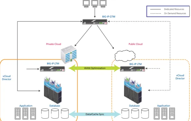
In the example scenario detailed in this guide, we use two instances of vCloud Director in our lab; one represents a private cloud, and the other represents a service provider’s public cloud. The two environments are connected via a WAN emulator. Our example application is the JPetStore demonstration application, together with VMware vCloud Director, vFabric SQLFire®, BIG-IP LTM, BIG-IP GTM, and F5 iControl®. Necessary application templates and virtualized infrastructure components have been pre-positioned at a cloud provider in a dormant state, and are activated and cloned as needed.
We used JPetStore, a freely available Java e-commerce application. In our example we have modified the configuration to use the database caching and replication technologies provided by the vFabric SQLFire product. We also partitioned the database table-space to allow inter-site data replication for order history and to maintain accurate inventory levels for order processing
Version Description
1.0 New deployment guide
1.1 • Changed GemStone SQL Fabric to vFabric SQLFire to reflect the change in the product name.
• Clarifed the scenerio description in Configuration Example section. We modified the JPetStore configuration and not the application itself.
at locations throughout the application infrastructure. This deployment uses a hybrid cloud computing model to dynamically scale out the application in response to elevated levels of application clients.
Our infrastructure scales out and back in based on business rules and the performance characteristics of the application. We measure the application response time in the private cloud, and begin to consume cloud provider resources in response to increased application latency. As load continues to increase, we programmatically deploy additional application servers in the public cloud and update the requisite infrastructure components to ensure the application continues to perform according to our defined profile.
Figure 1 Logical configuration example
Private Cloud Public Cloud
BIG-IP GTM
BIG-IP LTM BIG-IP LTM
vCloud Director vCloud
Director
WAN Optimization
Data/Cache Sync
On Demand Resources Dedicated Resources
Application
Hardware, software and infrastructure components
The following is a list of hardware, software and infrastructure components we used to perform the tasks in this deployment guide. These components will be used in any implementation (with the exception of WAN emulation), however, they do not need to be dedicated to this scenario.
Hardware and software components
The following is a list of the software and hardware components used for this implementation:
Role What we used Platform
Application Traffic Management F5 BIG-IP Global Traffic Manager (GTM) v10.2
F5 BIG-IP Local Traffic Manager (LTM) v10.2
F5 iControl SDK
- Appliance for GTM running on the 1600 platform at a minimum)
- Appliance for LTM + iSessions (current packaging prevents iSessions and GTM on the same platform (3600 platform at a minimum)
- BIG-IP LTM Virtual Edition (VE)
Application Server Apache Tomcat Cent OS 5.4 virtual machine
Application Environment Sun Java Development Kit (JDK) Cent OS 5.4 virtual machine
Example application JPetstore application Java
Admin clients Microsoft Windows 7 Windows OS virtual machines
Server Operating System Microsoft Windows 2008R2 server Windows OS virtual machines
Database - Oracle database (per vCloud Director
release notes)
- Microsoft SQL Server 2008
Oracle Enterprise Linux and Microsoft Windows virtual machines
Storage - Open Solaris
- NetApp Data OnTAP NFS server
- Sun Fire x4150 with Sun StorageTek J4200 array - NetApp FAS3160
WAN emulation (only necessary if you are deploying in a lab environment. Other WAN emulators can be used)
Candela LANforge 5.14 (can run in a VM, but dedicated hardware strongly recommended)
x86 server hardware with 4 ethernet interfaces
Cloud Services - VMware vCloud Service Director
- vCloud SDK
- VMware vShield - vSphere 4.0U1 - vCenter Server - ESX - ESXi - vSphere Client
- At least 2 server hosts for each vCloud Director cell as per vCloud Director documentation. We used 2 x Dell 2970 each with 16 GB RAM for the Public Cloud and 2 x HP DL 385 servers with 16GB RAM for the Private Cloud
- One chassis for VMware management services (running ESXi, vCenter Server, vCloud Director systems and Oracle Databases) these were all running in VMs in a third vSphere environment, not connected to either cloud
Infrastructure components
The following is a list of infrastructure components.
Domain Name Resolution BIND 9 Ubuntu 8 virtual machine
Accurate Network Time NTP Server Ubuntu 8 virtual machine
Browser plug-in for admin client Adobe Flash Administrative console
What We Used: Network Connections Description VMware
- ESX & ESXi - vCenter - vCloud Director - vShield - vMotion
A distinct network to coalesce management for infrastructure components. This network should be composed of an assigned VLAN and IP subnet. In testing VLAN 100 and the IP network of 10.1.100.0/255.255.252.0 was used. We label this tc_admin in our vSphere environments.
Oracle 11gR2 database servers
F5 BIG-IP GTM Appliance management interface F5 BIG-IP LTM Appliance management interface
LANforge management interface
Ethernet switches
VMware - vSphere (vCenter and ESX configured) - vCloud Director network mappings at site 1 (Private cloud) > Direct Organization Network connected to an external network which is backed by a dvPort Group. In our testing we used VLAN 1057 and 10.133.57.0/24 for the direct connect external network. In VSphere, we label this network "dvPG_vm_vcloud_private_external."
> Internal Organization vCNI network which is backed by an vCNI Network Pool. We used VLAN 1058 and
10.133.58.0/24 for the isolated network. In vSphere, we label this network "dvPG_vm_vcloud_private_internal." - vCloud Director network mappings at site 2 (Public cloud) > Internal Organization vCNI network which is backed by an vCNI Network Pool. In our testing we used VLAN 1059 and 10.133.59.0/24 for this network. In VSphere, we label this network "dvPG_vm_vcloud_public_external."
> Internal Organization vCNI network which is backed by an vCNI Network Pool. In our testing we used VLAN 1060 and 10.133.60.0/24 for this network. In VSphere, we label this network "dvPG_vm_vcloud_public_internal.
Networks for application traffic at each site:
At least two VLANs are required at each cloud site. One VLAN and IP network tuple will be assigned for inbound traffic to the cloud and one VLAN and IP network tuple will be assigned for private-internal cloud application traffic.
- VLAN - IPSubnet
A network is required for clients, and in our example for load generation. The VLAN and IP Subnet selected must also be made available to and configured on the LANforge. This allows the client WAN profile to be managed and configured
independently of the WAN emulation settings used between the 2 cloud sites. In our testing we used VLAN 1061 and
10.133.61.0/24 for the client network.
Additional components and recommendations
You should also have an orchestration tool, or implement a custom monitoring and execution tool. This solution requires a process to map business requirements to application performance. You need to establish baselines for your application and adapt orchestration as suitable for your environment.
In our deployment, we wrote a custom workflow process in Java. See
Configuring the infrastructure
In this section, we provide guidance on how to provision and allocate network, security, database, core services such as NTP and DNS, and perform the essential vCloud Director configuration tasks.
Important
It is outside the scope of this document to provide step-by-step procedures for the following tasks. Refer to the vendor’s documentation, online help, or support services offered by your cloud provider to supplement these steps.
Configuring NTP and DNS
Use the following guidance when configuring NTP and DNS:
◆ DNS
• Configure forward name resolution for all management systems. • Configure reverse name resolution for all IP addresses (vCloud
Director).
◆ NTP
• Configure NTP accessible by both sites.
• NTP needs to be accessed by vCloud Director, vCenter, Oracle DB, and vShield manager in each cloud.
• All clocks within each cloud environment must be within 2 seconds of each other.
Configuring the databases
Use the following guidance when configuring the databases:
◆ Configure the vCenter database for two vSphere vCenter servers at Version 4.0 U1 or higher (if using a Service Provider, only one is necessary at your private site).
• Microsoft SQL server is recommended over the embedded database. The Microsoft SQL Server can be installed on the same system as the vCenter server.
◆ vCloud Director database
1. Install the Oracle database system(s) (the required version can be found in the VMware vCloud Director documentation).
a) We recommend one server for each vCloud Director site. b) Create a new, empty, namespace for each database, as per the
vCloud Director documentation.
c) The Oracle system needs to be accessible from the vCloud Director management interfaces.
d) The Oracle database login account must have the following privileges: connect, grant resource, create trigger, create procedure, create sequence, and execute any procedure. • Logon to your Oracle instance as SYSTEM and execute the
following SQL commands to create the vCloud Director user
◆Create a user (we use vcloudusername) identified by a password (we use vclouduserpassword).
◆Grant RESOURCE, DBA, CONNECT to the user name you created.
Note:Do not use the Oracle system account to connect vCloud
Director hosts to the database
vCloud Director will create the necessary database schema on the first connect.
Configuring management
This section contains management guidance for ESX/ESXi, vCenter, and vCloud Director.
Configuring ESX/ESXi and vCenter management
Use the following guidance when configuring ESX/ESXi and vCenter: 1. Install the management PC for running the vSphere client - and
install the vSphere client.
2. Install ESX/ESXi version 4.0 U1 at each cloud site - ESX/ESXi must be activated with an Enterprise Plus license.
3. Install and configure vCenter to manage the ESX/ESXi hosts at each cloud site.
4. Configure the following items in each vCenter: a) Cluster for each site
b) Two resource pools in each cluster at each site. One to be used by vCloud Director, and another to be used when creating multiple VM vApps.
c) Datastores.
d) Configure the ESX/ESXi cluster to use Automated DRS. e) Create a vNetwork Distributed Switch at each site. In our
example, we used dvSW-priv-01 in the Private Cloud and
Configuring vCloud Director management
Use the following guidance for configuring vCloud Director management: 1. Install vCloud Director nodes for each site
a) Each needs at least two IP addresses - though three is preferable. • One for Service access.
• One for vSphere proxy. • One for management.
2. Configure vCloud Director for each site's provider resources. a) Create a Provider vDC. In our example, we named this provider
Public_provider for the Public Cloud and Private_provider in
the Private Cloud.
b) Add the vCenter to the vCloud Director as appropriate. c) Prepare the ESX/ESXi hosts with the vCloud Director agent. d) Map the vCenter resources to provider-side objects in the Public
vCloud Director.
• Provider DC to resource pool.
• Two Provider level vCloud external networks:
◆One connected to vNetwork Distributed Switch dvPort Group. In our example, we created a Provider vDC level External Network connected to an external network which is backed by a dvPort Group for access to and from the application environment. We labeled this
red_public. This network is connected to the vSphere
network labeled dvPG_vm_vcloud_public_external.
◆One connected to a vNetwork Distributed Switch dvPort Group. IN our example, we created another Provider vDC level External Network which is backed by a dvPort Group for access to the LTM-VE management interface. We labeled this Ext_Net_to_tc_admin. This network is connected to the vSphere network we labeled
tc_admin.
• One Provider vCloud Network Pool:
◆A network pool of type VCD Cloud Network Isolation. In our example, we assigned this network a VLAN ID of 1060 and attached it to the dvSW_01. We labeled this network pool as
blue_vCNI_dvPG_vm_vcloud_Public_internal.
e) Map the vCenter resources to provider-side objects in the Private vCloud Director.
◆ One connected to vNetwork Distributed Switch dvPort Group. In our example, we created a Provider vDC level External Network connected to an external network which is backed by a dvPort Group for access to and from the application environment. We labeled this
red_private. This network is connected to the vSphere
network labeled dvPG_vm_vcloud_private_external. • One Provider vCloud Network Pool:
◆ A network pool of type VCD Cloud Network Isolation. In our example, we assigned this network a VLAN ID of 1058 and attached it to the dvSW-priv-01. WE labeled this network pool as
blue_vCNI_dvPG_vm_vcloud_private_internal.
3. Datastores need to be provisioned for the vCloud Director.
Configuring the vSphere and physical networks
Use the following guidance for configuring the vSphere and physical network devices:
◆ vNetwork Distributed Switches for ESX/ESXi networking.
◆ The following tasks are per vCloud Director site: 1. Provision VLANs and IP subnets as needed. 2. Configure Ethernet switching:
a) Interconnect external VLANs with LANForge (if using WAN emulation) and ESX/ESXi hosts.
b) Interconnect all management interfaces
3. Install the two vSphere vCenter servers at Version 4.0 U1 or higher
Note: If using a Service Provider, only one is necessary.
Configuring security
Use the following guidance for configuring security:
◆ Install vShield managers for each site and configure ESX/ESXi
networking as per the vCloud Director documentation- vShield manager configuration only needs an IP address and DNS resolver configured. All other configuration is done automatically using reverse DNS and vCloud Director.
Configuring the vCloud Director
In this section, we configure the vCloud Director. You must have administrative access to complete these tasks.
Completing the Guided Tasks
Log into the vCloud Director web GUI as a Provider Administrator and complete all of the Guided Tasks as applicable for your configuration, using the networks that were mapped in Configuring management, on page 8. Consult the VMware documentation for specific information on
configuring the vCloud Director.
Note
Many of the tasks will vary based on site conditions; you must configure these as applicable for your configuration or consult your cloud provider. And some of the tasks may be performed by your cloud/service provider.
You need to create a new Organization, and add the appropriate Provider vDC Network Pools to the Organization vDC.
You must then create the Provider Networks - you need two External Organization Network - Direct Connections (note: do not choose NAT-routed connection as this will create a vShield Edge device for this network. The LTM -VE will be performing these functions) and one Internal Organization Network.
In our example, we created the following:
* Note: Provide the appropriate Network Mask, Default Gateway, DNS and Static IP Pool information. In our case we used 255.255.255.0 as Network Mask, 10.133.60.1 as Default Gateway, 10.133.61.240 as Primary DNS, and created a Static IP Pool as 10.133.60.101 - 10.133.60.150. (It is important to note the Default Gateway entered here. This IP will be used as a SeflIP on the LTM-VE).
Deploying the application in the private cloud
The final task in this section is to deploy the application in the private cloud. If the application is already a VM running in the vSphere 4 environment backing the vCloud Director installation, you may import from vCenter to vCloud Director. If not, create a vApp that contains the application. The vApp has to be exported to the .ovf format. Once in the .ovf format, the vApp can be transferred to the vCloud Director catalog.
For more information, refer to the VMware vCloud Director documentation.
Network Type Provider Network Names Organizational Network Names
External Direct Ext_Net_to_tc_Admin pub_org_ext_to_tc_admin
External Direct red_public pub_org_ext_pub
Configuring the BIG-IP LTM
In this section, we configure the BIG-IP LTM devices. First, we configure the physical BIG-IP LTM appliance on site at the private location. Later in this section, we configure the LTM Virtual Edition (VE) for each
organization's virtual data center in the public cloud. This section contains the following subsections:
• Configuring the physical BIG-IP LTM in the private cloud
• Deploying the BIG-IP LTM as a vApp in the public cloud, on page 19 • Configuring the BIG-IP LTM for the vFabric SQLFire locator and WAN
gateway services, on page 27
Prerequisites
The following are prerequisites and configuration notes for this section:
◆ Deploy the BIG-IP LTM in fixed infrastructure connected to the private cloud network (where the servers are located), and connected to the external network (where clients are located).
◆ Activate the device license and provision LTM for nominal and WOM for WOM lite.
◆ Configure all VLANs and self IP addresses to connect so that internal and external networks are connected.
Configuring the physical BIG-IP LTM in the private cloud
In this section, we configure the physical BIG-IP LTM appliance that resides in the private location for application traffic. In our example, we use Apache Tomcat and JPetStore as our application.
Creating the health monitor
The first task is to set up a health monitors for the servers. This procedure is optional, but very strongly recommended. In our example, we create a monitor that uses Send and Receive Strings to ensure the servers are delivering the proper content.
To create a health monitor
1. On the Main tab, expand Local Traffic, and then click Monitors. 2. Click the Create button. The New Monitor screen opens.
3. In the Name box, type a name for the Monitor. In our example, we type Tomcat-http-monitor. 4. From the Type list, select http.
5. In the Configuration section, in the Interval and Timeout boxes, type an Interval and Timeout. We recommend at least a (1:3) +1 ratio between the interval and the timeout. In our example, we use a
Interval of 30 and a Timeout of 91.
6. In the Send String box, you can optionally type a Send string. In our example for JPetStore, we type the following (as a single line):
GET /JPetStoreApp/shop/viewCategory.shtml?categoryId=BIRDS HTTP/1.1\r\nHost: 10.133.57.20\r\nConnection: Close\r\n\r\n
7. In the Receive String box, type the response you expect from the Send String. In our example, we type:
<h2>Birds</h2>
8. Click the Finished button. The new monitor is added to the list.
Figure 2 New health monitor page
Creating the pool
The next step is to define a load balancing pool for the servers. A BIG-IP pool is a set of devices grouped together to receive traffic according to a load balancing method. This pool uses the monitor you just created.
To create the pool
1. On the Main tab, expand Local Traffic, and then click Pools. The Pool screen opens.
2. Click the Create button. The New Pool screen opens.
3. From the Configuration list, select Advanced. 4. In the Name box, type a name for your pool.
In our example, we use Tomcat-app-pool.
5. In the Health Monitors section, select the name of the monitor you created in Creating the health monitor, and click the Add (<<) button. In our example, we select Tomcat-http-monitor. 6. In the Slow Ramp Time box, type a number of seconds that
corresponds to the expected number of requests per second. For example, if the server farm is receiving 2000 requests per second, and there are 5 servers, each device receives approximately 400 requests per second. When a server that has been offline comes back online, we don't want the BIG-IP to immediately send 400 requests to that device. In our example, we set the Slow Ramp Time to 30 seconds.
Note: The Slow Ramp Time option does not appear unless you have selected Advanced from the Configuration list.
7. From the Load Balancing Method list, choose your preferred load balancing method (different load balancing methods may yield optimal results for a particular network).
In our example, we select Least Connections (Node)
8. In this pool, we leave the Priority Group Activation Disabled. 9. In the New Members section, make sure the New Address option
button is selected.
10. In the Address box, add the first Apache server to the pool. In our example, we type 10.133.58.101.
11. In the Service Port box, type 80 or select HTTP from the list. 12. Click the Add button to add the member to the list.
13. Repeat steps 8-10 for each server you want to add to the pool. In our example, we repeat these steps again adding 10.133.58.102. 14. Click the Finished button.
Creating profiles
The BIG-IP system uses configuration objects called profiles. A profile is an object that contains user-configurable settings for controlling the behavior of a particular type of network traffic, such as HTTP connections. Using profiles enhances your control over managing network traffic, and makes traffic-management tasks easier and more efficient.
Although it is possible to use the default profiles, we strongly recommend you create new profiles based on the default parent profiles, even if you do not change any of the settings initially. Creating new profiles allows you to easily modify the profile settings specific to this deployment, and ensures you do not accidentally overwrite the default profile.
Creating an HTTP profile
The first new profile we create is an HTTP profile. The HTTP profile contains numerous configuration options for how the BIG-IP LTM system handles HTTP traffic. In the following example, we base our HTTP profile off of the http-wan-optimized-compression-caching parent.
To create a new HTTP profile
1. On the Main tab, expand Local Traffic, and then click Profiles. The HTTP Profiles screen opens.
2. Click the Create button. The New HTTP Profile screen opens. 3. In the Name box, type a name for this profile. In our example, we
type Tomcat-app-opt.
4. From the Parent Profile list, select
http-wan-optimized-compression-caching.
5. Optional: If you using the BIG-IP LTM to offload SSL, in the Settings section, check the Custom box for Redirect Rewrite, and from the Redirect Rewrite list, select Match. See Configuring the WAN emulator, on page 31 for more information.
6. Modify any of the other settings as applicable for your network. In our example, we leave the settings at their default levels.
7. Click the Finished button.
Creating the TCP profile
The next profile we create are the TCP profile. In our example, we create a LAN optimized TCP profile.
To create a new TCP profile
1. On the Main tab, expand Local Traffic, and thenclick Profiles. The HTTP Profiles screen opens.
2. On the Menu bar, from the Protocol menu, click tcp. 3. Click the Create button.
The New TCP Profile screen opens.
4. In the Name box, type a name for this profile. In our example, we type Tomcat-tcp-lan.
5. From the Parent Profile list, select tcp-lan-optimized.
6. Modify any of the settings as applicable for your network. In our example, we leave the settings at their default levels.
7. Click the Finished button.
Optional:
Creating persistence profile
Persistence is essential in an application server environment, especially in Java environments managed by Tomcat. For every user session, memory space is allocated on a particular server, so returning a user to the same machine, creates efficiency for both the server and the user.
For Tomcat persistence, there are two options. If the only persistence being used by your application is based on jSession cookie, the BIG-IP system's built-in cookie hash method can be used to maintain persistence. If URI based session persistence is also used, then it is our recommendation to use the BIG-IP system’s Universal Inspection Engine.
To create a new cookie persistence profile
1. On the Main tab, expand Local Traffic, and then click Profiles. The HTTP Profiles screen opens.
2. On the Menu bar, click Persistence. The Persistence Profiles screen opens. 3. Click the Create button.
The New Persistence Profile screen opens.
4. In the Name box, type a name for this profile. In our example, we type Tomcat-cookie.
5. From the Persistence Type list, select Cookie.
The configuration options for cookie persistence appear. 6. From the Cookie Method row, click the Custom box and then
select CookieHash.
7. In the Cookie Name box, type JSESSIONID. 8. Click the Finished button
Important
If your application only uses JSession cookie, it is safe to use the built-in cookie persistence profile which yields the fastest persistence results.
If using persistence, it is a good idea to have a backup persistence method. In this example, we use Source Address Affinity.
To create a Source Address Affinity persistence profile
1. On the Main tab, expand Local Traffic, and then click Profiles. The HTTP Profiles screen opens.
2. On the Menu bar, click Persistence. The Persistence Profiles screen opens. 3. Click the Create button.
4. In the Name box, type a name for this profile. In our example, we type Tomcat-source.
5. From the Persistence Type list, select Source Address Affinity. The configuration options appear.
6. Modify any of the settings as applicable for your network. In our example, we leave the settings at their default levels.
1. Click the Finished button.
Creating a OneConnect profile
The final profile we create is a OneConnect profile. With OneConnect enabled, client requests can utilize existing, server-side connections, thus reducing the number of server-side connections that a server must negotiate to service those requests. This can provide significant performance
improvements for Apache implementations. For more information on OneConnect, see the BIG-IP LTM documentation.
In our example, we leave all the options at their default settings. You can configure these options as appropriate for your network.
To create a new OneConnect profile
1. On the Main tab, expand Local Traffic, and then click Profiles. The HTTP Profiles screen opens.
2. On the Menu bar, from the Other menu, click OneConnect. The Persistence Profiles screen opens.
3. Click the Create button.
The New HTTP Profile screen opens.
4. In the Name box, type a name for this profile. In our example, we type Tomcat-oneconnect.
5. From the Parent Profile list, ensure that oneconnect is selected. 6. Modify any of the other settings as applicable for your network. In
our example, we leave the settings at their default levels. 7. Click the Finished button.
Creating the virtual server
Next, we configure a virtual server that references the profiles and pool you created in the preceding procedures.
To create the virtual server
1. On the Main tab, expand Local Traffic, and then click Virtual Servers.
The Virtual Servers screen opens.
3. In the Name box, type a name for this virtual server. In our example, we type jpetstore-vs.
Note: We recommend naming your pool with function of the Tomcat server being load balanced, which makes administration and debugging simpler.
4. In the Destination section, select the Host option button.
5. In the Address box, type the IP address of this virtual server. In our example, we use 10.133.57.20.
6. In the Service Port box, type 80, or select HTTP from the list. 7. From the Configuration list, select Advanced.
The Advanced configuration options appear. 8. Leave the Type list at the default setting: Standard.
9. From the Protocol Profile (Client) list select the name of the profile you created in the Creating the TCP profile section. In our example, we select Tomcat-tcp-lan.
10. From the Protocol Profile (Server) list, select the name of the profile you created in the Creating the TCP profile section. In our example, we select Tomcat-tcp-lan.
11. From the OneConnect Profile list, select the name of the profile you created in Creating a OneConnect profile. In our example, we select Tomcat-oneconnect.
12. From the HTTP Profile list, select the name of the profile you created in the Creating an HTTP profile section. In our example, we select Tomcat-app-opt.
13. In the Resources section, from the Default Pool list, select the pool you created in the Creating the pool section. In our example, we select Tomcat-app-pool.
14. From the Default Persistence Profile list, select the persistence profile you created in the Optional: Creating persistence profile
section. In our example, we select Tomcat-cookie.
15. From the Fallback Persistence Profile list, select the fallback persistence profile you created in the Optional: Creating persistence profile section. In our example, we select Tomcat-source.
16. Click the Finished button.
The BIG-IP LTM HTTP configuration for Apache Tomcat application is complete. If you are using the BIG-IP system to offload SSL, see Appendix C: Configuring the BIG-IP LTM to offload SSL, on page 60.
Deploying the BIG-IP LTM as a vApp in the public cloud
The next task is to deploy BIG-IP LTM Virtual Edition(s) as a vApp in the public cloud environment.
You need make sure of the following before beginning the procedures in this section.
• Activate the device license and provision LTM for nominal and WOM for WOM Lite
• Configure all VLANs and self IP addresses to connect so that the direct access network is the “external” network on the LTM and the “internal” network is connected to the isolated network.
Before beginning the BIG-IP LTM configuration, you need to upload and instantiate the BIG-IP LTM VE in the public cloud. Use the following procedures.
Uploading and instantiating the BIG-IP LTM VE in the public cloud
Use the following procedure to upload and instantiate the BIG-IP LTM Virtual Edition in the public cloud.
To upload and instantiate the BIG-IP LTM in the public
cloud
1. Download the latest BIG-IP LTM Virtual Edition from
https://downloads.f5.com/esd/index.jsp to a computer which has the ability to upload to the Public cloud.
In our example, we download BIGIP-10.2.0.1707.0.ova.zip. 2. Check MD5.
3. Unzip the file you downloaded to a temporary directory.
Note: VMware Cloud Director transfer service allows for the upload of .ovf files and their associated .vmdk files. Uploading .ova files is not yet supported. An .ova file is simply an uncompressed archive of the .ovf and associated files. This archive must be unpacked out to its five constituent files. (F5_icon, .cert, .ovf, .mf, and .vmdk).
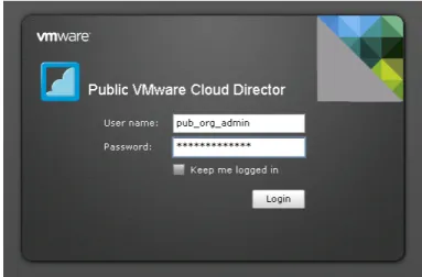
4. Log into the Public vCloud Organization URL as a user with catalog upload permissions.
Figure 3 Logon page of the VMware Public Cloud Director
5. Click the Catalogs tab.
6. Click the name of the catalog into which you would like to upload the LTM-VE. In our example, we click pub_org_catalog01.
Figure 4 VMware Public vCloud Catalogs tab
7. Click the Upload icon. The Upload OVF package as a vApp Template dialog box opens.
8. Click the Choose file button, and then browse to the
BIGIP-10.2.0.1707.0.ovf file that you unzipped and unpacked in
Step 3.
9. From the vDC list, select the vDC for which this .ovf will be made available. In our example, we chose Public.
10. In the Name box, type a name. In our example, we type
LTM-VE-10.2. You can optionally type a description in the
Description box.
12. Click Upload.
Figure 5 Upload OVF package dialog box
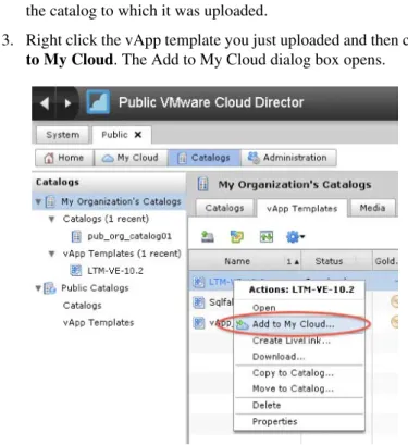
Once the file is uploaded it is available as a vApp template within the catalog to which it was uploaded.
13. Right click the vApp template you just uploaded and then click Add
to My Cloud. The Add to My Cloud dialog box opens.
14. In the Name box, type a name. This is the name used to refer to the vApp in vCD. (vCD will prepend a unique identifier to this name in vCenter). You can optionally type a description.
In our example, we type F5_LTM-VE_10-2.
15. In the Leases section, select times from the Runtime lease and
Storage lease boxes appropriate for your environment. In our
example, we choose Never Expires for both.
16. Click Next. The Configure Virtual Machines page opens.
17. On the Configure Virtual Machines page, configure the following: a) In the Full Name box, type a name. In our example, we type
LTM-VE-10-2.
b) In the Computer Name box, type the name that the VM is identified as in the Cloud. In our example, we type
LTM-VE-10-2.
Important: Do NOT use guest customization - it will invalidate your BIG-IP LTM VE license
c) Click the NIC 0 option button to designate it as the primary NIC. This will be the management NIC.
From the Network list, select the appropriate network label which connects to your management network. In our example, we choose pub_org_ext_to_tc_admin.
From the IP assignment list, select Static - Manual, and then type an appropriate static IP address for your network. In our example, we type 10.1.102.75.
d) In the NIC 1 row, from the Network list, select the appropriate network label which connects to your organization’s vCNI internal network. In our example, we select pub_org_blue_int. From the IP assignment list, select Static - Manual, and then type an appropriate static IP address for your network. In our example, we type 10.133.50.254.
e) In the NIC 2 row, from the Network list, select the appropriate network label which connects to your organization’s direct connected external network. In our example, we select
pub_org_red_ext.
From the IP assignment list, select Static - Manual, and then type an appropriate static IP address for your network. In our example, we type 10.133.59.254.
f) In the NIC 3 row, from the Network list, select the appropriate network. In our example, we leave this NIC undefined.
18. Click the Next button.
Figure 7 Configure the Virtual Machines page of the Add to My Cloud dialog box
19. On the Configure Networking page, it is very important that you DO NOT check the Fence vAPP box. You can check the Show
networking details box to double check the networking details.
20. Click Next. 21. Click Finish.
Configuring the BIG-IP LTM VE to support the application
In this section, we configure the BIG-IP LTM VE to support the application. Because many of the following procedures are the same for VE as the physical BIG-IP LTM you just configured, we refer back to those procedures instead of repeating the same information. Full procedures are included for the new objects, such as the iRule and Statistics profile. Note that this section does not include configuring members in the load balancing pool. Pool members will be added programmatically (the workflow engine uses iControl to add pool members).
Creating the health monitor
To create the health monitor, use the procedure Creating the health monitor, on page 12. Give the monitor a unique name.
Creating the pool
To create the pool, use the procedure Creating the pool, on page 13. Give the pool a unique name. In our example we used petshop_http.
Important: Do NOT add any members to this pool. After Step 7, click the
Finished button.
Creating the profiles
To create the profiles, use the following procedures. Note that we configure an new Statistics Profile.
• Creating an HTTP profile, on page 15 • Creating the TCP profile, on page 15
• Optional: Creating persistence profile, on page 16 • Creating a OneConnect profile, on page 17
Creating the Statistics profile
In this procedure, we create a Statistics profile. In our deployment scenario there are two distinct scaling actions that take place and are initiated by our workflow process according to our established business rules. We define the vertical scaling action as an event that our workflow process executes to initially activate and begin consuming public cloud resources. We define the horizontal scaling action as an event that our workflow process executes to deploy additional application capacity in the public cloud. These state changes and capacity operations are affected using the VMware vCloud API and the F5 iControl API.
The two rules governing our infrastructure operations are:
1. When 40% of the orders confirmed in the system over a one minute period exceed 15ms of processing time activate public cloud resources.
2. vApp systems running in the public cloud shall accept a maximum number of 30 connections at any given time.
In measuring application response time, we build a histogram using a Statistics profile and an iRule, then our workflow process periodically retrieves the values using iControl. The Statistics profile is composed of fields for response time ranges, each with a counter in it. The rages are <5ms, 5-7ms, 7-12ms, 12-15ms, and >15ms. The iRule to appropriately increment these counters according to the order confirmation page latency is in the following procedure.
Important
You must follow this procedure exactly as described below, including all names and fields. If you do not, the iRule you create in the following section will not work correctly.
To create the Statistics profile
1. On the Main tab, expand Local Traffic, and then click Profiles. 2. On the Menu bar, from the Other menu, select Statistics. 3. Click the Create button.
4. In the Name box, type responseHistogram.
Important:You must use this name, as this profile is referenced from the iRule you create in the next section.
5. Click the Custom box above the Settings box to check all of the Custom boxes.
6. In the Field 1 box, type zeroToFive. 7. In the Field 2 box, type fiveToSeven. 8. In the Field 3 box, type sevenToThirteen. 9. In the Field 4 box, type thirteenToFifteen. 10. In the Field 5 box, type greaterThanFifteen. 11. Click the Finished button.
Creating the iRule
In this section, we create the iRule that references the Statistics profile you just created.
To create the iRule
1. On the Main tab, expand Local Traffic, and then click iRules. 2. Click the Create button.
3. In the Name box, type a name for this rule. In our example, we type
increment-irule.
4. In the Definition box, copy and paste the iRule on the following page, omitting the line numbers.
5. Click Finished.
Creating the virtual server
To create the virtual server, use the procedure Creating the virtual server, on page 17, using the BIG-IP LTM objects you created in this section, with the following exceptions:
◆ After Step 12, from the Statistics Profile list, select the name of the Statistics profile you created in Creating the Statistics profile, on page 24.
◆ After selecting the Statistics profile, in the Resources section, from the
iRules row, in the Available box, select the iRule you created in
Creating the iRule, on page 25, and the click the Add (<<) button to move it to the Enabled list. In our example, we select increment-irule.
1 2 3 4 5 6 7 8 9 10 11 12 13 14 15 16 17 18 19 20 21 22 23 24 25 26 27 28 29 30 31 32 33
when HTTP_REQUEST {
if { [HTTP::uri] starts_with "/JPetStoreApp/shop/newOrder.shtml?" } { set http_request_time [clock clicks -milliseconds]
set isCheckout "true" }
else {
set isCheckout "false" }
}
when HTTP_RESPONSE {
if { $isCheckout eq "true" } {
#if it's not coming from the local LTM monitoring or GTM self IP record the statistic set response_time [expr [clock clicks -milliseconds] - $http_request_time]
log local0. "response time: $response_time ms for [IP::client_addr]" if { $response_time < 5 } {
STATS::incr responseHistogram zeroToFive 1 }
elseif { $response_time < 7 } {
STATS::incr responseHistogram fiveToSeven 1 }
elseif { $response_time < 13 } {
STATS::incr responseHistogram sevenToThirteen 1 }
elseif { $response_time < 15} {
STATS::incr responseHistogram thirteenToFifteen 1 }
else {
STATS::incr responseHistogram greaterThanFifteen 1 }
} }
Configuring the BIG-IP LTM for the vFabric SQLFire locator and
WAN gateway services
Next, we configure the BIG-IP LTM for the vFabric SQLFire locator and WAN gateway services in each location.
Creating the pool
In this procedure, we create the load balancing pool.
To create the pool
1. On the Main tab, expand Local Traffic, and then click Pools. 2. Click the Create button. The New Pool screen opens.
3. In the Name box, type a name for your pool. We type vfabric-pool. 4. In the Health Monitors section, gateway_icmp, and click the Add
(<<) button.
5. From the Load Balancing Method list, choose your preferred load balancing method (different load balancing methods may yield optimal results for a particular network).
In our example, we select Least Connections (node). 6. In this pool, we leave the Priority Group Activation Disabled. 7. In the New Members section, make sure the New Address option
button is selected.
8. In the Address box, type the IP address of one of the servers. In our example, we use 10.133.58.51.
9. In the Service Port box, type 9001.
10. Click the Add button to add the member to the list.
11. Repeat steps 8-10 for each server you want to add to the pool. 12. Click the Finished button.
Creating the TCP profiles
The next task is to create the TCP profiles. We recommend configuring LAN and WAN optimized TCP profiles.
To create a new TCP profile
1. On the Main tab, expand Local Traffic, and thenclick Profiles. The HTTP Profiles screen opens.
2. On the Menu bar, from the Protocol menu, click tcp. 3. Click the Create button.
4. In the Name box, type a name for this profile. In our example, we type tcp-wan-vfabric.
5. From the Parent Profile list, select tcp-wan-optimized.
6. Configure any of the other settings as applicable for your network. 7. Important: Click the Repeat button.
8. In the Name box, type a name for the LAN optimized profile. In our example, we type tcp-lan-vfabric.
9. From the Parent Profile list, select tcp-lan-optimized.
10. Configure any of the other settings as applicable for your network. 11. Click the Finished button.
Configuring iSessions between the Private Cloud LTM and the LTM-VE in
the Public Cloud
The next task is to configure iSessions between the BIG-IP LTM and the vApp, for optimizing database cache and replication traffic. The following procedures should be performed on each BIG-IP LTM (and VE).
Configuring the Remote Endpoint
In this procedure, we create the remote end of the WOM tunnel and point it to the BIG-IP in the other data center.
1. On the Main tab, expand WAN Optimization, then click Remote
Endpoints.
2. Click the Create button.
3. In the Remote Endpoint IP Address box, type the address of the other BIG-IP’s WAN Self-IP address.
4. Modify any of the options as applicable for your configuration. In our example, we leave the settings at the default.
5. Click Finished.
Running the WOM Quick Start Wizard
The WOM Quick Start Wizard is used to configure the initial parameters.
To run the WOM Quick Start Wizard
1. On the Main tab, expand WAN Optimization, and then click Quick Start.
2. In the WAN Self IP Address box, type the appropriate IP address. 3. Leave the Discovery list set to Enabled.
4. In the Select VLANs section, from the LAN VLANs row, select the appropriate VLAN and click the Add (<<) button to move it
Selected box.
5. From the WAN VLANs row, select the appropriate VLAN and click the Add (<<) button to move it Selected box.
6. Leave Outbound iSession to WAN set to serverssl.
7. Leave Inbound iSession from WAN set to wom-default-clientssl. 8. Leave Application Data Encryption set to Disabled.
9. In the Create Optimized Applications section, do NOT check any applications. We create applications this later in the guide.
10. Important: Click the Apply button at this step. If you do not, the WOM tunnel is not set up properly.
Creating the iSession Profile
The next task is to create the iSession profile.
To create the iSession profile
1. On the Main tab, expand Local Traffic, and then click Profiles
2. On the Menu bar, from the Services menu, click iSession. 3. Click the Create button.
4. In the Name box, give the profile a name. In our example, we use
application-isession.
5. In the Compression Settings section, from the Deduplication row, click the Custom button, and then from the list, select Disabled. 6. Leave the settings at the defaults.
7. Click the Finished button.
Creating the optimized applications
The next task is to create the optimized applications. For this procedure, you return to the WAN Optimization Quick Start. In our example, we use port 0 to capture all ports. You can also make this more specific by configuring individual ports. For instructions, see the BIG-IP documentation.
To create the optimized applications
1. On the Main tab, expand WAN Optimization, and then click Quick Start.
2. At the bottom of the page, in the Other Applications section, click
Click this link to create other optimized applications.
3. In the Name box, type a name for this application. 4. In the Port box, type 0.
5. In the Enabled LAN VLANs section, from the Available list, select the appropriate VLAN and click the Add (<<) button.
6. From the iSession Profile list, select the profile you created in
Creating the iSession Profile, on page 29. 7. Click Finished.
8. Important: Repeat this entire procedure on the peer BIG-IP LTM in the private cloud.
Creating the wildcard virtual server
The next task is to create a wildcard virtual server. Use the following procedure.
To create the wildcard virtual server
1. On the Main tab, expand Local Traffic, and then click Virtual
Servers.
2. Click the Create button.
3. In the Name box, type a name for this virtual server. In our example, we type vfabric_wildcard.
4. In the Address box, type 0.0.0.0.
5. In the Service Port box, type * or select *All Ports from the list. 6. From the Configuration list, select Advanced.
7. From the Protocol Profile (Client) list, select the profile you created in Creating the TCP profiles, on page 27. In our example, we select tcp-wan-vfabric.
8. From the Protocol Profile (Server) list, select the profile you created in Creating the TCP profiles, on page 27. In our example, we select tcp-lan-vfabric.
9. From the SNAT Pool list, select Automap. 10. From the Source Port list, select Change.
11. In the WAN Optimization section, from the iSession Profile list, select the profile you created in Creating the iSession Profile, on page 29
12. In the Resources section, from the Default Pool list, select the pool you created in the Creating the pool section. In our example, we select vfabric-pool.
13. Click Finished.
Important
Return to Creating the pool, on page 1-27 and repeat all the procedures for the vFabric SQLFire locator and the WAN gateway services in each location.
Configuring the WAN emulator
If staged in a lab environment or when WAN emulation is required, the next task is to configure your WAN emulator. In our example, we use
LANForge. You can use other commercial WAN emulators such as Shunra, or open source ones such as Dummynet.
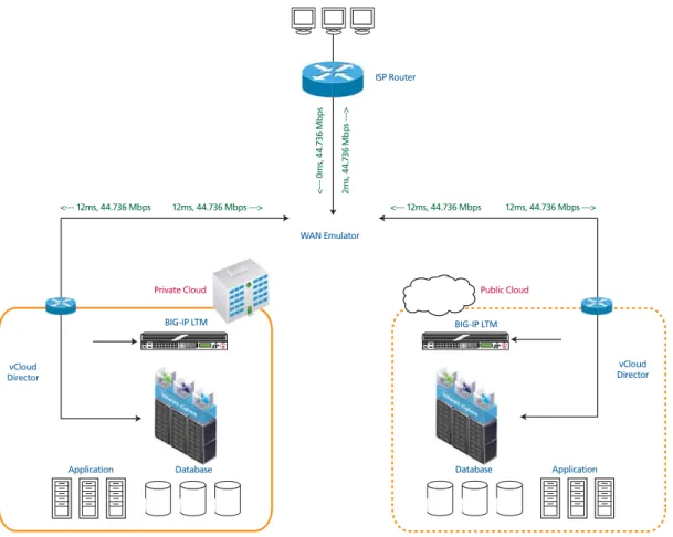
The following diagram shows our LANForge configuration.
Figure 8 LANForge WAN emulation diagram
If configuring LANForge, keeping in mind the following: 1. Needs to access four networks and VLANs
a) Management
b) Private site (public side) c) Public site (public side) d) Client site
Private Cloud Public Cloud
BIG-IP LTM BIG-IP LTM
vCloud Director vCloud
Director
Application Application
<--- 12ms, 44.736 Mbps 12ms, 44.736 Mbps ---> <--- 12ms, 44.736 Mbps 12ms, 44.736 Mbps --->
0
m
s,
44
.7
36
M
b
p
s
2m
s,
4
4.
73
6 M
b
p
s
-
-->
WAN Emulator
Database Database
2. Configure virtual routers and establish connectivity among the three IP subnets in use.
a) One virtual router for each cloud site, interconnected
b) One virtual router connected to the client site, interconnected with the private site
3. Configure WAN emulation parameters
a) In our setup we use 45Mb/s bandwidth between the public and private cloud sites. 12ms each way on each link = 48ms RTT. 0.10% packet loss
b) In our setup we use 1.544 Mb/s bandwidth for the client
Configuring vFabric SQLFire
The following are the vFabric SQLFire configuration tasks. For more information on vFabric SQLFire, see
http://communities.vmware.com/community/vmtn/appplatform/vfabric_sqlfire
Configuring vFabric SQLFire locator nodes
Configure vFabric SQLFire locator nodes in each cloud environment. The locator node must be reachable and known before the first application instance comes up. This allows locator and WAN gateway services to be deployed independently of the vFabric SQLFire application services. The remote site knows where to find the service, and queues changes until the service is reachable (this should be abstracted to cover an arbitrary database technology).
Installing and configuring vFabric SQLFire and the application in
the private cloud
In this section, you install and configure the vFabric SQLFire and the application. Use the following tasks and guidance when installing and configuring vFabric SQLFire and the application.
Tip
We include the scripts we used in this section in Appendix B: vFabric SQLFire scripts, on page 48.
You must perform the following tasks: 1. Install Apache Tomcat server. 2. Install JDK.
3. Install vFabric SQLFire.
4. Download and deploy JPetStore version from VMware community site.
5. Modify the schema SQL to include a WAN Gateway.
The gatewayI.sql file points to the hub at the other cloud. See
Appendix B: vFabric SQLFire scripts, on page 48 for our example
a) Modify tables to use the gateway.
To point the tables to the hub, you have to add “HUB(ALL)” at the end of their table creation DDLs. This was done to the line item and orders tables. Ensure that /etc/hosts has an entry for the IP address and hostname that is used on the private network b) Create startup scripts - no IP addresses needed, use DNS or
c) On the infrastructure node (locator and WAN gateway) Kill processes and cleanup the old database.
d) Startup vFabric SQLFire - set properties for forcing use of IP addresses.
e) Bootstrap the application database tables
f) Setup autostarting for tomcat/sqlfabric in rc.local using startup scripts.
Configuring the Application server nodes
Use the following guidance to configure the application server nodes.
1. clean - kills all jvms that happen to be running and deletes all
persistence files (this includes the data dictionary, so the schema can be fetched from INF node) go - starts sqlfabric, then starts tomcat. 2. go - see Appendix B: vFabric SQLFire scripts, on page 48 for our
example
3. go.init - see Appendix B: vFabric SQLFire scripts, on page 48 for
our example
4. Setup autostarting for tomcat/sqlfabric in rc.local using startup scripts.
Copying the private cloud configuration to the public cloud
Use the following guidance to copy the private cloud configuration to the public cloud:
1. Copy private cloud vFabric SQLFire configuration to the public cloud systems and reserve the IPs in the WAN gateway
configuration.
2. Modify the schema bootstrap on the public cloud to use a negative order ID (UPDATE SEQUENCE SET NEXTID=-2000000).
Configuring Routes
The next task is to create the Routes on the BIG-IP system. Each BIG-IP LTM needs to be able to route to the other BIG-IP LTM, as well as have a route for the remote network where application services reside. We assume that the firewall is the default route (.1).
For WAN optimization to occur properly between sites, each BIG-IP LTM will also need a route to the remote networks via the appropriate next hop gateway. In our example, we add a route for 10.10.2.0/24 via 192.168.2.1 in Datacenter 1.
To create the routes
1. On the Main tab, expand Network, and then click Routes. 2. Click the Create button.
3. From the Type list, select Route.
4. In the Destination box, type the IP network address of the remote network you wish to reach.
5. In the Netmask box, type the associated Netmask.
6. From the Resource list, make sure Use Gateway is selected. 7. From the Gateway Address list, select IP Address, and then type
the IP address of the remote internal network via the next hop gateway.
8. Click Repeat. Repeat this procedure to add a route so that the device can reach the peer LTM.
Configuring the BIG-IP GTM
The next task is to deploy BIG-IP GTM in the fixed infrastructure connected to the external private network.
Note
Before starting the following procedures, you should already have configured the appropriate VLANs, self IP addresses and listeners. For specific instructions how to configure these objects, see the BIG-IP documentation, available on Ask F5.
Configuring the BIG-IP GTM from the command line
The first task in this section is to configure the following from the BIG-IP command line. For additional information, refer to the BIG-IP
documentation.
◆ From the GTM command line, run the bigip_add command to exchange security information with each LTM.
◆ From the GTM command line, run big3d_install on the GTM to ensure matching big3d_agents between the GTM and each LTM.
◆ On each BIG-IP LTM, run bigip_add to exchange security information with the GTM.
◆ On each BIG-IP LTM, run bigip_add on each LTM to exchange security information with the peer LTM.
Configure the GTM for the application
We configure GTM to use the global availability load balancing method for the wide IP. Virtual servers in the public cloud are configured at a higher priority than those in the private cloud; for ease of deployment and minimizing configuration changes during the cloud burst action. This ensures that when public cloud resources are activated and deactivated GTM does not need to be reconfigured.
We use application QoS and Global Availability to set connection limits on the virtual server in each data center to ensure that global availability.
Creating the data centers
In this task you need to create two data centers, called Public and Private respectively, that correspond to your physical data centers.
To create the data centers
1. On the Main tab of the navigation pane, expand Global Traffic and click Data Centers. The main screen for data centers opens.
2. Click the Create button. The New Data Center screen opens. 3. In the Name box, type a name for this data center. In our example,
we type Public.
4. Complete the rest of the configuration as applicable for your deployment.
5. Click the Repeat button. Repeat this procedure for the Private data center.
6. Click Finished.
Creating the GTM servers
The next task is to create servers on the BIG-IP GTM system. In this configuration, we create a two servers for the BIG-IP LTM (one in the private network and one in the public, and one for the GTM in the private network
To create the GTM servers
1. On the Main tab of the navigation pane, expand Global Traffic and click Servers. The main screen for servers opens.
2. Click the Create button. The New Server screen opens. 3. In the Name box, type a name that identifies the Local Traffic
Manager. In our example, we type Public-BIG-IP.
4. Configure the General properties of the server as applicable for your deployment.
5. In the Resources section, from the Virtual Server Discovery list, select Enabled.
6. Click the Repeat button.
7. Repeat this entire procedure to create a GTM server for the BIG-IP LTM in the Public network.
8. Click Repeat and then repeat this procedure for the other BIG-IP LTM.
9. Click Repeat again, configure the virtual server for the GTM in the private network, and then click the Finished button.
Creating the GTM pools
The next task is to create a pools on the BIG-IP GTM system.
To create a GTM pool
1. On the Main tab of the navigation pane, expand Global Traffic and click Pools (located under Wide IPs).
3. In the Name box, type a name for the pool. In our example, we type
Public_pool.
4. In the Load Balancing Method section, from the Preferred list, select Global Availability. We recommend using Round Robin as a fallback.
5. In the Member List section, from the Virtual Server list, select one of the virtual servers you created in preceding procedure, and click the Add button. Note that you must select the virtual server by IP Address and port number combination. In our example, we select
10.133.39.51:80.
Repeat this step to add the other virtual server.
6. Configure the other settings as applicable for your deployment 7. Click the Repeat button, and repeat this procedure to create a pool
for the virtual server in the public data center.
Important: For this pool, in the Fallback IPv4 box, type the IP address of the Private datacenter virtual server.
8. Click Finished.
Creating a wide IP on the GTM
The final step in the GTM configuration is to create a wide IP that includes both newly-created pools, and uses the fully qualified domain name (FQDN) you wish to use for your applications.
To create a wide IP
1. On the Main tab of the navigation pane, expand Global Traffic and click Wide IPs.
2. Click the Create button. The New Wide IP screen opens.
3. In the Name box, type a name for the Wide IP. In our example, we type cloud.example.com.
4. From the State list, ensure that Enabled is selected.
5. From the Pools section, from the Load Balancing Method list, select Global Availability.
6. From the Persistence list, select Enabled.
7. In the Pool List section, from the Pool list, select the name of the pool you created in Creating the GTM pools, on page 37, and then click the Add button. In our example, we select Public_pool. Repeat this step for the Private pool. The Private pool must be last in the list.
8. From the Last Resort Pool list, select the pool in the private data center.
Uploading your application as a vApp to the public
cloud
The next task is to upload your application as a vApp to the public cloud and register it in the catalog as a template. You need to log on to the vClould Director web UI as an Organizational Administrator, and create a catalog to which you will upload vApps.
Refer to your Service Provider or VMware documentation on how to upload the application.