Electronic Communications of the EASST
Volume 25 (2010)
Proceedings of the Workshop
Visual Formalisms for Patterns
at VL/HCC 2009
Towards Generalizing Visual Process Patterns
Christian Soltenborn and Gregor Engels
10 pages
Guest Editors: Paolo Bottoni, Esther Guerra, Juan de Lara
Managing Editors: Tiziana Margaria, Julia Padberg, Gabriele Taentzer
Towards Generalizing Visual Process Patterns
Christian Soltenborn and Gregor Engels
University of Paderborn
{christian,engels}@uni-paderborn.de
Abstract:Visual Process Patterns(VPP) is a visual language to describe constraints on the behavior of UML Activities. They have been developed for the sake of formu-lating and verifying requirements on business process models in a visual, intuitive way (with UML Activities being one possible description language). In the VPP approach, a visual process pattern is translated into anLTLformula, which can then be verified against a transition system describing the behavior of the Activity under consideration.
In this paper, we aim at generalizing VPP. We show how to formulate patterns more generally, using an enhanced version of the concrete syntax of the behavioral model under consideration. Additionally, we describe how these more general patterns can be verified against a model’s behavior.
Keywords:Pattern, semantics, verification, business process, activity, state machine
1 Introduction
Business processes are a crucial part of many companies’ business, and therefore have to fulfill certain domain specific and quality requirements. Such requirements can e.g. be specified by means of so-called process patterns. For instance, such a process pattern can state that “after each production action a quality check has to be performed prior to delivery”.
Given the complexity of many business processes, it would be desirable to be able to auto-matically verify such requirements against a particular business process. This implies that the modeler has to somehow formalize the requirements.
Unfortunately, thesemantic gapbetween a visual, flow-oriented business process model and most formal specification languages (e.g., temporal logic [CES86]) is quite large. Therefore, the translation of (informal) requirements into a (formal) specification language is a challenging task, and must be expected to be beyond knowledge of the average business analyst.
Visual Process Pattern(VPP) [F¨or08] aim at bridging that semantic gap by allowing the busi-ness analyst to model the requirements in basically the same language as the busibusi-ness process itself. In the case of VPP, the underlying modeling language is UML Activities [Obj09]; its fit-ness for busifit-ness process modeling is obvious. See Fig.1for an example business process from the insurance domain, modeled as a UML Activity.
Consequently, F¨orster et.al. [FESS07,FSES06,FES05] have suggested an Activity based vi-sual language which allows for the specification and verification of requirements like “After each production action, a quality check has to be performed prior to delivery”. Figure2gives a first impression of a VPP representation of that requirement, which will serve as a running example for the rest of this paper; more details of VPP will be explained in Sect.2.
Towards Generalizing Visual Process Patterns produce part 2 receive order ship send invoice close bill [else] [order accepted] report order
report rejected order
report payment test quality receive payment fill order produce part 1
Figure 1. Example business process (adopted from [14, p. 312])
report order
test quality ship
<<complete>> a) Process constraint #1
<<all>>
produce
b) Process constraint #2 close order
Figure 2. Process patterns for constraints #1 and #2
can state:
Process constraint #1: Before an order is being closed, records of the received orders have to be made.
The constraint implies that the Action “report order” is cuted at some point before the Action “close order” is exe-cuted, but it does not require that the Action “report order” is executeddirectlybefore “close order”.
It is an important property of typical process require-ments that they frequently contain rather loose or incom-plete temporal/logical relationships between Actions. In a concrete business process there may be many other Actions executed in between “report order” and “close order” with-out contradicting the pattern. Since the original semantics of an ActivityEdge as described in the UML Superstruc-ture is that Action “close order” is enabled immediately when Action “report order” terminates [14], we introduced the stereotypeafterfor an ActivityEdge to express that some Action has to be executed after another but not nec-essarily directly following it. Stereotyping of model ele-ments is the standard extension mechanism of the UML. Using stereotypes, model elements can be given additional or extended semantics. Figure 2a shows process constraint #1 modeled in our PPSL. The curly line in Fig. 2a is a visualization option of theafterstereotype. In the re-mainder, we refer to this sort of stereotyped ActivityEdge asAfterEdge.
Being able to express such loose order relationships in process patterns is also a necessary prerequisite to enable
flexible application of the process patterns since pattern ac-tions and acac-tions of the original business process usually need to be weaved together. If the pattern designer wants to specify that there may not be other Actions being executed in between two Actions of a pattern, a regular ActivityEdge without stereotype can be used in the pattern.
Process constraint #1 could be read in two directions. Ei-ther “every time an order is closed this has to be preceeded by reporting an order” or “every report of an order must be followed by closing the order”. It is important to have the possibility to distinguish these two cases in the process constraint language. This can be done using the stereo-typeallfor Actions. It denotes whether the implication given by the AfterEdge in the constraint refers toall“close order” Actions orall“report order” Actions. In the remain-der, we will refer to an Action having anallstereotype asAllAction. The multi-node in Figs. 2 and 3 are a visu-alization option of the AllAction. It is also possible to use AllActions on both sides of the AfterEdge or ActivityEdge denoting that both implications have to be fulfilled. Conse-quently, it is a well-formedness rule for our language that at least one of two Actions being connected by an AfterEdge or ActivityEdge is an AllAction.
The next process constraint that we want to consider is:
Process constraint #2: After each production action a quality check has to be performed prior to delivery.
Process constraints #2 is similar to process constraint #1 but contains precisely spoken two different constraints put together. The first requirement is that after each produc-tion acproduc-tion there has to be a quality check and the second requirement is that before shipping a product, the quality has to be checked. This is why the actions “produce” and “ship” in the process pattern are AllNodes. The use of a regular ActivityEdge between ”test quality” and ”ship” sets the requirement that shipping has to bedirectlypreceded by the quality test. There may not be other actions executed in between these two actions.
If we now compare the process constraints with the ex-ample business process in Fig. 1, we can see that it does not have an action called “produce” like the pattern in Fig. Figure 1: Example business process, modeled as a UML Activity
produce part 2 receive order ship send invoice close bill [else] [order accepted] report order
report rejected order
report payment test quality receive payment fill order produce part 1
Figure 1. Example business process (adopted from [14, p. 312])
report order
test quality ship
<<complete>>
a) Process constraint #1
<<all>>
produce
b) Process constraint #2
close order
Figure 2. Process patterns for constraints #1
and #2
can state:
Process constraint #1:
Before an order is being closed,
records of the received orders have to be made.
The constraint implies that the Action “report order” is
cuted at some point before the Action “close order” is
exe-cuted, but it does not require that the Action “report order”
is executed
directly
before “close order”.
It is an important property of typical process
require-ments that they frequently contain rather loose or
incom-plete temporal/logical relationships between Actions. In a
concrete business process there may be many other Actions
executed in between “report order” and “close order”
with-out contradicting the pattern. Since the original semantics
of an ActivityEdge as described in the UML
Superstruc-ture is that Action “close order” is enabled immediately
when Action “report order” terminates [14], we introduced
the stereotype
after
for an ActivityEdge to express that
some Action has to be executed after another but not
nec-essarily directly following it. Stereotyping of model
ele-ments is the standard extension mechanism of the UML.
Using stereotypes, model elements can be given additional
or extended semantics. Figure 2a shows process constraint
#1 modeled in our PPSL. The curly line in Fig. 2a is a
visualization option of the
after
stereotype. In the
re-mainder, we refer to this sort of stereotyped ActivityEdge
as
AfterEdge
.
Being able to express such loose order relationships in
process patterns is also a necessary prerequisite to enable
flexible application of the process patterns since pattern
ac-tions and acac-tions of the original business process usually
need to be weaved together. If the pattern designer wants to
specify that there may not be other Actions being executed
in between two Actions of a pattern, a regular ActivityEdge
without stereotype can be used in the pattern.
Process constraint #1 could be read in two directions.
Ei-ther “every time an order is closed this has to be preceeded
by reporting an order” or “every report of an order must
be followed by closing the order”. It is important to have
the possibility to distinguish these two cases in the process
constraint language. This can be done using the
stereo-type
all
for Actions. It denotes whether the implication
given by the AfterEdge in the constraint refers to
all
“close
order” Actions or
all
“report order” Actions. In the
remain-der, we will refer to an Action having an
all
stereotype
as
AllAction
. The multi-node in Figs. 2 and 3 are a
visu-alization option of the AllAction. It is also possible to use
AllActions on both sides of the AfterEdge or ActivityEdge
denoting that both implications have to be fulfilled.
Conse-quently, it is a well-formedness rule for our language that at
least one of two Actions being connected by an AfterEdge
or ActivityEdge is an AllAction.
The next process constraint that we want to consider is:
Process constraint #2:
After each production action a
quality check has to be performed prior to delivery.
Process constraints #2 is similar to process constraint #1
but contains precisely spoken two different constraints put
together. The first requirement is that after each
produc-tion acproduc-tion there has to be a quality check and the second
requirement is that before shipping a product, the quality
has to be checked. This is why the actions “produce” and
“ship” in the process pattern are AllNodes. The use of a
regular ActivityEdge between ”test quality” and ”ship” sets
the requirement that shipping has to be
directly
preceded by
the quality test. There may not be other actions executed in
between these two actions.
If we now compare the process constraints with the
ex-ample business process in Fig. 1, we can see that it does
not have an action called “produce” like the pattern in Fig.
Figure 2: Visual process pattern formalizing the requirement “After each production action a quality check has to be performed prior to delivery”
F¨orster’s approach is well-suited for the formulation of requirements put on UML Activities and the execution of the contained Actions, but it does not allow for the formulation of require-ments about other Activity constructs (e.g., whether a token has arrived at a FinalNode) or even against other languages (e.g., UML State Machines). This is due to the fact that F¨orster’s lan-guage is dedicated to formulating requirements against UML Activities only. As a consequence, UML Actions (i.e., the places in an Activity where actual work takes place) are an important element of that language. As a result, the language is not able to express requirements against models which do not contain Actions (e.g., models which are not UML Activities).
In this paper, we describe how to generalize the VPP approach to be able to do exactly that. We will show how to formulate and verify requirements on arbitrary languages. For that, we will reuse a part of F¨orster’s language. The basic idea is to replace Actions in a VPP with arbitrary states of execution of the underlying model, and to connect these states with the flow elements used in VPPs. The states of execution of the underlying behavioral model can be described in concrete syntax.
Structure of paper: In the next section, we will give more insight into the VPP approach. We will point out some technical details of VPP and demonstrate them using the running example introduced above. Based on that, Sect.3will then show how the VPP approach can be general-ized such that requirements can be formulated and verified against arbitrary language constructs. Section4presents work related to our approach, and the last section concludes and points out the current state and the future of our work.
2 Visual Process Pattern
We have mentioned in the introduction that a VPP is expressed as a number of Actions, connected by custom flow elements (we have seen an example in Fig. 2). In this section, we want to precisely define the example’s semantics, and we want to shed light on the technical background of VPP.
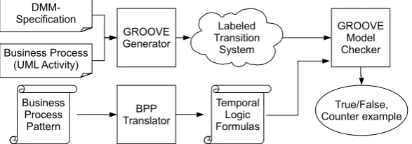
Business Process (UML Activity)
DMM-Specification
GROOVE Generator
Labeled Transition
System
Business Process Pattern
GROOVE Model Checker
True/False, Counter example Temporal
Logic Formulas BPP
Translator
Figure 3: Overview of the VPP approach
We start with an assumption, though: We expect to receive the semantics of a business pro-cess model as alabeled transition system(LTS), where the labels contain information about the model’s execution. A trace through such an LTS is the sequence of labels we get on one of the possible “ways” through the LTS. We will later see how this is actually realized in the VPP approach, and how to use this fact for generalizing the approach.
The idea of VPP is to visually describe temporal properties of a model. For instance, one wants to express that “when ActionAis executed, ActionBwill be executed at some point in the future”. The interested reader will immediately see that the temporal part of the above statement (“when eventA, then eventually eventB”) can easily be expressed using temporal logic.
This is indeed what the VPP approach does: in [FESS07], the authors have defined the visual pattern language by mapping the custom flow elements into the temporal logic dialect LTL. For instance, the example VPP depicted as Fig.2is translated into the two formulasG(produce→
F test quality)andG(ship→Y test quality). Figure3shows the whole underlying process. In LTL, expressions about pathsGstands for “all future states”,Fmeans “some future state”, andY translates to “the previous state”. It now becomes clear how the formulas are related to our example VPP: The first expression is true for a trace of the LTS, if for all the trace’s states it is the case that if labelproduceoccurs, label “test quality” will occur in the future. The second expression is true for traces such that if label “ship” occurs, label “test quality” must have been the previous label. Note that an expression is true for an LTS iff it is true for all (possibly infinite) traces through that LTS.
So far, we have seen how to express VPPs into according LTL formulas which can then be verified against an appropriately labeled transition system. Our next step will be the generation of such an LTS. This is whereDynamic Meta Modelingcomes into play.
2.1 Dynamic Meta Modeling
Dynamic Meta Modeling (DMM) [Hau05] is a semantics specification technique targeted at visual behavioral modeling languages whose abstract syntax is defined by means of ametamodel. The idea of DMM is to enhance such a given metamodel with concepts needed to express states of execution of a language’s model, leading to a so-called runtime metamodel. In a second step, operational rules are defined which describe how instances of the runtime metamodel (i.e., models in a certain state of execution) change in time (i.e., which state(s) of execution will be
Towards Generalizing Visual Process Patterns
Semantics Definition
Syntax Definition
Transition System
States Expression
Model
Operational rules
conforms to
Semantic metamodeling
conforms to
Metamodel Graph transformation rules
semantic
mapping Runtime metamodel
Language
Model (Instance) conforms to
conforms to
typed over
Figure 4: Overview of the DMM approach
reached from a certain state according to the language’s behavior). Such a DMM rule has a precondition which must be fulfilled for the rule to match; if this is the case, the rule is applied, leading to a new state. The DMM approach is depicted as Fig.4.
Let us illustrate the above using the example language of UML Activities: The runtime meta-model of UML Activities adds concepts such as an ActivityExecution class, a Token class1etc., whereas the operational rules describe how tokens flow through an Activity during execution. For instance, one of the mentioned DMM rules makes sure that an Action is executed if all its incoming edges carry at least one token. If this is the case, the Action starts execution.
A DMM specification together with an instance of the runtime metamodel give rise to an LTS, where states are states of execution of the according model, transitions are applications of oper-ational rules, and labels are names of operoper-ational rules. The instance of the runtime metamodel serves as the start state of the LTS. The LTS can then be analyzed with model checking tech-niques, e.g. to verify LTL formulas as defined above: The idea is to refer within these formulas to the names of appropriate DMM rules corresponding to the desired states of execution (e.g., the execution of a particular Action).
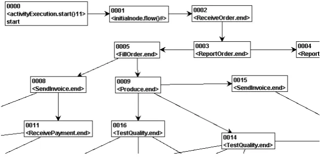
Technically, DMM is based ongraph transformations[EEKR99]. The instances of the runtime metamodel are treated as (typed) graphs, and the DMM rules manipulate these graphs. As a result, DMM specifications are not only formal, but also easily understandable due to their visual nature. The execution of DMM specifications as well as the model checking are performed using the GROOVE tool set [Ren04,KR06], an excerpt of the resulting LTS is depicted as Fig.5. See [Hau05,F¨or08] for more details on DMM and the way VPPs make use of it.
1 Note that since UML 2.0, the semantics of Activities is based on token flow.
and verifying constraints for business processes, it is not
in-tended to be a graphical notation for temporal logic in
gen-eral.
Furthermore we show how the example process patterns
of Sect. 3 are translated into temporal logic and whether
the business process of Fig. 1 conforms to these patterns.
Finally in Sect. 4.3 we show how the verification process
shown in Fig. 4 can be embedded in a tool chain, using
state-of-the-art model checkers. This tool support supports
the business process designer in verifying the application of
the process patterns he/she selected.
4.1
Generation of the Labeled Transition
System
The semantics of a visual language is defined in the
DMM framework by a semantic domain meta model and
a set of meta operations. The semantic domain meta model
describes the semantical concepts of the language. For
ex-ample, to be able to express the semantics of Activity
Dia-grams, the semantic concept ActionExecution is defined as
a class in the semantic domain meta model. This concept
denotes a currently running execution of an Action. For
each semantic concept that relates to behavior it captures
this behavior in a set of meta operations. The meta
opera-tions are defined by rules represented as UML
communica-tion diagrams. These communicacommunica-tion diagrams are given a
formal interpretation based on graph transformation rules.
Given the set of DMM rules for a particular language
and a user-defined model expressed in the same language,
a labeled transition system (LTS) is generated by a DMM
interpreter that reflects all possible behaviors to the model.
In the DMM approach, the GROOVE (GRaphical
Object-Oriented VErification) tool set [15] has been chosen as
DMM interpreter to produce the resulting labeled system.
Using the GROOVE tool, the set of DMM rules for UML
2.0 Activity Diagrams, and given a user-defined Activity
Diagram, which is in our case the business process, we can
generate a LTS that specifies the exact execution paths of
the Activity Diagram. Figure 5 shows an excerpt of the
re-sulting LTS from the example in Fig. 1. Each state in the
LTS represents a state in the execution of the Activity
Di-agram. The labels in the states represent the fact that the
corresponding Action is actually executing.
A name of an Action in the business process refers to a
certain
Behavior. Since the business process and the
pro-cess pattern may have been devised by different persons
us-ing different Behavior namespaces, a mappus-ing needs to be
defined. This mapping is part of the tool chain described in
Sect. 4.3. For the formalization, without loss of generality,
we assume that the Behavior namespaces are synchronized.
The DMM approach for UML Activity Diagrams
incor-porates the semantics of the UML 2.0 Superstructure [14]
Figure 5. Excerpt of the transition system
re-sulting from the example business process in
Fig. 1b generated using DMM and GROOVE.
for model elements of the packages
StructuredActivities
and
IntermediateActivities. These semantics implemented in
DMM include all important issues described in the UML
Specification like traverse-to-completion, the fact that
Ac-tions capture all of their input tokens in one atomic step,
etc. Concurrency in the Activity Diagram leads to a
transi-tion system that contains all possible interleavings between
the concurrent Actions.
In the next section we specify how the process patterns
can be translated into temporal logic formulas which can be
checked against the transition system.
4.2
Formalization of Process Patterns
The formalization of the process patterns is presented in
two consecutive steps. First, the notion of
Pattern Graph
is
defined. Secondly, the translation of a process pattern into
temporal logic is established.
A process pattern is represented by a
Pattern Graph.
Definition 1.
A
Pattern Graph (PG)
is a tuple
PG
=
(
N
,
E
)
where
N
is the set of nodes and
E
is the set of edges,
i.e., the set of tuples
N
×
N
. The notation
e
(
n
1, n
2)
is
equiv-alent with
e
∈
E
∧
e
= (
n
1, n
2)
.
The set
N
is divided into different disjoint subsets,
N
=
N
a∪
N
d∪
N
m∪
N
f∪
N
jwhere
N
ais the set of
Ac-tionNodes,
N
dis the set of
DecisionNodes,
N
mis the set
of
MergeNodes,
N
fis the set of
ForkNodes, and
N
jis the
set of
JoinNodes.
The set of
ControlNodes, denoted by
N
c, is defined as
N
c=
N
d∪
N
m∪
N
f∪
N
j.
The set of edges
E
is divided into two disjoint sets
E
=
E
d∪
E
a, where
E
dis the set of ActivityEdges,
E
ais the set of AfterEdges,
and
E
d∩
E
a=
∅
.
The set of AllActions is denoted by
N
all⊆
N
a.
In the remainder of this section, we explain how process
patterns can be expressed by
Linear-time temporal logic
Figure 5: Excerpt of the transition system resulting from the example business process in Fig.1, generated using DMM and GROOVE
3 Generalization of VPP
In the last section, we have seen how VPPs are translated into temporal logic formulas which can then be model checked against the LTS derived from the language’s semantics specification and the business process itself (which serves as the start state). We have also seen how VPP uses DMM: For every Action of the business process, a corresponding DMM rule exists; the according label in the LTS corresponds to the execution of the according rule.
However, as mentioned earlier, this approach does not help if we e.g. want to formulate re-quirements on other language elements than Actions, let alone other behavioral languages. This is not possible with VPPs since the usage of Actions is “hardcoded” into the approach, as we have seen earlier. For instance, we would like to be able to express requirements like “When ActionAis executed, the Activity will always terminate properly”. However, the VPP language does not contain any constructs allowing to express requirements on other elements than Actions. One solution could be to directly refer to rules of the semantics specification within a VPP expression. For instance, instead of connecting Actions with the VPP flow elements (as seen in Fig.2), we could connect a representation of the rules corresponding to the behavior of interest. However, this has two serious drawbacks: First, the business analyst creating the VPPs needs to have knowledge about the rules contained in the semantics specification: Which rules do exist, and which situations do they correspond to? Second (and even worse), we would also like to be able to express requirements about states of execution of our model for which no corresponding rule exists. For instance, we might want to express that at some point in time, both Actions A and B are executed in parallel; however, there is no corresponding rule for that kind of requirement.
Fortunately, GROOVE offers the concept of so-called property rules. The next section will show how these property rules can be used to formulate requirements about a much broader class of states of execution.
Towards Generalizing Visual Process Patterns
3.1 Property Rules
Property rules are rules which have a precondition, but they do not change the states they are applied to. In other words: if such a rule matches a state, the rule is applied, leading to a self-transition of the according state. Technically, a property rule is a graph transformation rule having the same left-hand and right-hand graphs.
These property rules can be used for our goal of formulating requirements in a more flexible way: For every state property of interest, an according property rule is defined and added to the DMM ruleset. For instance, if we are interested in the state where Actions A and B are executed in parallel, we just need to create a property rule describing exactly that situation: The rule would contain the according Actions which would both carry a token, corresponding to the fact that they are both executed.
The resulting LTS will contain some additional transitions: Every state which fulfills the for-mulated property will have a label with the property rule’s name. This allows for the verification of temporal formulas about those properties as described in Sect.2. Note that the new LTS will be stuttering equivalent to the original transition system, i.e., if we remove all occurences of property rules from the traces of our new LTS, the resulting set of traces is equal to the set of traces of the original LTS. To put it differently: Adding property rules to an existing ruleset does not significantly change the ruleset’s semantics.
Note also that using property rules still allows to verify all requirements formulated with “plain” VPPs as described by F¨orster. This is done by deriving property rules from the DMM rules used within the verification process in a trivial way. For each DMM rule used in the verification process (i.e., each rule referenced by our original VPPs), we introduce a new property rule whose precondition is fulfilled if the according Action is executed. If we compute the LTS, every state which was labeled with one of the original rules will additionally be labeled with the according property rule. This means that we can still check the requirement by using the same LTL formulas as before; the only difference is that the rules referenced within these formulas have been replaced with the corresponding property rules.
3.2 Specification of State Properties
But how to specify property rules? Our assumption is that the business analyst knows the se-mantics of the modeling language used (otherwise she will probably not be able to come up with a meaningful model). Therefore, it seems reasonable to use a concrete syntax of the runtime metamodel for specifying the property rules, since we want their appearance to be as close to the original language as possible.
Let us illustrate this with a small example in the domain of Activities: We have seen above that the semantics of Activities is based on token flow, and that the DMM runtime metamodel of UML Activities therefore contains a Token class. An obvious visualization of the Token concept is a black, filled dot which is drawn at the language element the token is located. Figure6shows an example property rule: The rule matches if a token is sitting at an ActivityFinalNode.
Besides being intuitive and easily understandable, the suggested representation of property rules has another advantage: Having a concrete syntax for the runtime part of the language allows for the (animated) visualization of the execution of a model, e.g. for using it within a
Figure 6: A property rule as concrete syntax; the rule matches if a token is sitting on a FinalNode.
Figure 7: A VPP expression making use of property rules.
visual debugger, which is indeed part of one of our research projects (more on this in Sect.5).
3.3 Formulating VPPs Using Property Rules
It is now straight-forward how to use property rules within a VPP. Instead of referring to a concrete Action within one of the boxes contained in the VPP, a property rule is used which describes the properties of the state of interest. Figure7shows such a VPP realizing the require-ment “When ActionAis executed, the Activity will always terminate properly”: the left Action of the VPP contains Action Acarrying a token (corresponding to that Action being executed), the right part shows a FinalNode carrying a token (corresponding to the whole Activity being terminated).
Of course, the boxes can still be connected using the flow elements contained in the VPP language (as we did in Fig.7). As a result, the translation to temporal logic nearly remains unchanged. The only difference is that instead of using a reference to an existing DMM rule within a VPP, the according property rule is referenced.
Finally, it is now easy to see how this approach can be used for formulating requirements against other behavioral languages: for instance, in the case of UML State Machines, the runtime metamodel will most likely contain the concept of a “marker” which shows the current state(s) the machine is in. Having a concrete syntax for that marker concept, the marker can then be used to formulate requirements like “When the State Machine is in state A, it will eventually be in stateB”.
4 Related Work
The relatedwork of this paper mainly falls into two categories: workflow and process patterns and the verification of formal properties against workflows and processes.
Workflow and Process Patterns Van der Aalst et.al. [AHKB03] have suggested a number of workflow patterns describing several types of control flow structures in workflow systems. Using Petri nets, their main focus was to identify typical control flow structures contained in workflows, and to use this knowledge to assess existing workflow management systems and workflow specification languages for expressiveness. Ambler [Amb96] suggests the application of process patterns to software development processes; however, his approach does not contain a formal underpinning which could be used for automatic verification of such processes.
Towards Generalizing Visual Process Patterns
Verification of Workflow and Process Properties Kindler and van der Aalst [KA99] describe how to verify Petri Nets for general properties like soundness and liveness, but their approach does not support the verification of user-defined properties raising e.g. from domain-specific requirements. Janssen et.al. [JMM+99] suggest an approach for the verification of business processes using model checking techniques which is based on a proprietary process modeling language. The authors formalize different basic constraints; again, the approach does not allow for the verification of custom, user-defined properties.
5 Conclusion
In this paper, we have shown how to generalize the VPP approach, which deals with the visual specification of formal requirements against business processes. For this, we have briefly intro-duced the VPP approach, and we have explained how DMM and GROOVE are used to perform the verification of such requirements in Sect.2.
Based on that, we have shown in Sect.3how to replace the “hard-coded” Action rules of the DMM approach with so-called property rules, i.e., rules which do not change states they are ap-plied to, but are still represented as labels in the resulting LTS. We have shown how to formulate the property rules using a concrete syntax of the runtime metamodel which is part of the DMM specification. To demonstrate our approach, we have shown how to reformulate existing VPPs using property rules, and we have provided a simple process requirement which could not be formulated using the existing VPP language, but can be formulated with our approach. Addi-tionally, we have described how to compose property rules to requirements on the whole LTS, borrowing the flow constructs and their mapping to LTL from F¨orster’s VPP approach.
Future Work We are currently working on incorporating the described approach into our DMM tooling. This involves several steps: First, we need to investigate a reasonable way to define a concrete syntax for a runtime metamodel as used in the DMM specification technique (given that the syntax metamodel of the language is already equipped with a concrete syntax).
Additionally, as mentioned earlier, we plan to reuse the concrete syntax of the runtime meta-model for a visual debugger for languages having a DMM specification. The general idea is to animate the execution of a behavioral model (in the case of UML Activities, that animation would basically show the flowing of tokens through the Activity to be debugged). A first step in this direction has already been performed as part of a diploma thesis [Ban09].
If the verification shows that one of our VPPs does not hold for a particular model, the model checker will produce a counter example showing under which circumstances the violation of the VPP occurs. That counter example is expected to be very helpful for the business analyst when fixing the model’s flaws. Using the visual debugger as described in the previous paragraph, we want to back-propagate that counter example to the business analyst in an intuitive, easily understandable way.
Finally, we plan to visually model thesoundnessrequirements against UML Activities iden-tified in [ESW07]. Having shown the general usefulness of our approach that way, we plan to perform a larger case study in the context of DMM and our notion of VPPs.
Acknowledgements: Thanks to Nils Bandener for last-minute technical support.
Bibliography
[AHKB03] W. M. P. van der Aalst, A. H. M. ter Hofstede, B. Kiepuszewski, A. P. Barros. Workflow Patterns.Distributed and Parallel Databases14(1):5–51, 2003.
[Amb96] S. W. Ambler.Process Patterns - Building Large-Scale Systems Using Object Tech-nology. SIGS Books/Cambridge University Press, Cambridge, 1996.
[Ban09] N. Bandener. Visual Interpreter and Debugger for Dynamic Models Based on the Eclipse Platform. Master’s thesis, University of Paderborn, 2009.
[CES86] E. M. Clarke, E. A. Emerson, A. P. Sistla. Automatic Verification of Finite-State Concurrent Systems using Temporal Logic Specifications. ACM Trans. Program. Lang. Syst.8(2):244–263, 1986.
doi:http://doi.acm.org/10.1145/5397.5399
[EEKR99] H. Ehrig, G. Engels, H.-J. Kreowski, G. Rozenberg (eds.). Handbook of Graph Grammars and Computing by Graph Transformation, Vol. 2: Applications, Lan-guages, and Tools. World Scientific Publishing Co., Inc., River Edge, NJ, USA, 1999.
[ESW07] G. Engels, C. Soltenborn, H. Wehrheim. Analysis of UML Activities using Dynamic Meta Modeling. In Bosangue and Johnsen (eds.),Proceedings of the FMOODS 2007 Conference. LNCS 4468, pp. 76–90. Springer, 2007.
[FES05] A. F¨orster, G. Engels, T. Schattkowsky. Activity Diagram Patterns for Modeling Quality Constraints in Business Processes. In L. C. Briand (ed.),Proceedings of the 8th International Conference on Model Driven Engineering Languages and Systems (MoDELS 2005), Montego Bay (Jamaica). Pp. 2–16. Springer, 2005.
[FESS07] A. F¨orster, G. Engels, T. Schattkowsky, R. V. D. Straeten. Verification of Business Process Quality Constraints Based on Visual Process Patterns. InTASE. Pp. 197– 208. IEEE Computer Society, 2007.
[F¨or08] A. F¨orster. Pattern-Based Business Process Design and Verification. PhD thesis, University of Paderborn, 2008.
[FSES06] A. F¨orster, T. Schattkowsky, G. Engels, R. V. D. Straeten. A Pattern-driven Develop-ment Process for Quality Standard-conforming Business Process Models. InIEEE Symposium on Visual Languages and Human-Centric Computing (VL/HCC 2006), Brighton (UK). Pp. 135–142. IEEE Computer Society, 2006.
[Hau05] J. H. Hausmann. Dynamic Meta Modeling. PhD thesis, University of Paderborn, 2005.
[JMM+99] W. Janssen, R. Mateescu, S. Mauw, P. Fennema, P. van der Stappen. Model Checking
for Managers. In Dams et al. (eds.),SPIN. Lecture Notes in Computer Science 1680, pp. 92–107. Springer, 1999.
Towards Generalizing Visual Process Patterns
[KA99] E. Kindler, W. M. P. van der Aalst. Liveness, Fairness, and Recurrence in Petri Nets.
Information Processing Letters70(6):269–27, 1999.
[KR06] H. Kastenberg, A. Rensink. Model Checking Dynamic States in GROOVE. In Val-mari (ed.),SPIN. Lecture Notes in Computer Science 3925, pp. 299–305. Springer, 2006.
[Obj09] Object Management Group. OMG Unified Modeling Language (OMG UML) – Su-perstructure, Version 2.2.http://www.omg.org/docs/formal/09-02-02.pdf, 2 2009.
[Ren04] A. Rensink. The GROOVE Simulator: A Tool for State Space Generation. In Pfaltz et al. (eds.), AGTIVE 2003 – Revised Selected and Invited Papers. LNCS 3062, pp. 479–485. Springer, 2004.
![Figure 1. Example business process (adopted from [14, p. 312])produce](https://thumb-us.123doks.com/thumbv2/123dok_us/7813069.2086394/3.595.96.493.150.237/figure-example-business-process-adopted-from-p-produce.webp)