Proceedings of the
Seventh International Workshop on
Graph Transformation and Visual Modeling Techniques
(GT-VMT 2008)
Verifying Model Transformations by Structural Correspondence
Anantha Narayanan and Gabor Karsai
14 pages
Guest Editors: Claudia Ermel, Reiko Heckel, Juan de Lara
Managing Editors: Tiziana Margaria, Julia Padberg, Gabriele Taentzer
Verifying Model Transformations by Structural Correspondence
Anantha Narayanan1and Gabor Karsai1
1Institute for Software Integrated Systems,
Vanderbilt University Nashville, TN 37203 USA
Abstract: Model transformations play a significant role in model based software development, and the correctness of the transformation is crucial to the success of the development effort. We have previously shown how we can use bisimulation to verify the preservation of certain behavioral properties across a transformation. However, transformations are often used to construct structurally different models, and we might wish to ensure that there is some structural correspondence to the original model. It may be possible to verify such transformations without having to explicitly specify the dynamic semantics of the source and target languages. In this paper, we present a technique to verify such transformations, by first specifying certain structural correspondence rules between the source and target languages, and extending the transformation so that these rules can be easily evaluated on the instance models. This will allow us to conclude if the output model has the expected structure. The verification is performed at the instance level, meaning that each execution of the transformation is verified. We will also look at some examples using this technique.
Keywords:Verification, Model transformations
1
Introduction
Model transformations that translate a source model into an output model are often expressed in the form of rewriting rules, and can be classified according to a number of categories [MV05]. However, the correctness of a model transformation depends on several factors, such as whether the transformation terminates, whether the output model complies with the syntactical rules of the output language, and others. One question crucial to the correctness of a transformation is whether it achieved the intended result of mapping the semantics of the input model into that of the output model. For instance, a transformation from a Statechart model to a non-hierarchical FSM model can be said to be correct if the output model truly reproduces the behavior of the original Statechart model.
end of a transformation can be used to verify if those instances were correctly transformed. In this paper, we explore a technique to specifystructural correspondencerules, which can be used to decide if the transformation resulted in an output model with the expected structure. This will be specified along with the transformation, and evaluated for each execution of the transformation, to check whether the output model of that execution satisfies the correspondence rules.
2
Background
2.1 GReAT
GReAT [AKL03] is a language framework for specifying and executing model transformations using graph transformation. It is a meta-model based transformation tool implemented within the framework of GME [LBM+01]. One of the key features of GReAT is the ability to define cross-language elements by composing the source and target meta-models, and introducing new vertex and edge types that can be temporarily used during the transformation. Such cross-meta-model associations are calledcross-links. Note that a similar idea is present in Triple Graph Grammars [Sch95]. This ability of GReAT allows us to track relationships between elements of the source and target models during the course of the transformation, as the target model is being constructed from the source model. This feature plays a crucial role in our technique to provide assurances about the correctness of a model transformation.
2.2 Instance Based Verification of Model Transformations
Verifying the correctness of model transformations in general is as difficult as verifying compil-ers for high-level languages. But for practical purposes, a transformation may be said to have ‘executed correctly’ if a certain instance of its execution produced an output model that pre-served certain properties of interest. We call that instance ‘certified correct’. This idea is similar to the work of Denney and Fischer in [DF05], where a program generator is extended to produce logical annotations necessary for formal verification of certain safety properties. An automated theorem prover uses these annotations to find proofs for the safety properties for the generated code. Note that this does not prove the safety of the code generator, but only of a particular instance of generated code.
In our previous effort [NK06], we have shown that it is both practical and prudent to verify the correctness of every execution of a model transformation, as opposed to finding a correctness proof for the transformation specification. This makes the verification tractable, and can also find errors introduced during the implementation of a transformation that may have been specified correctly.
Figure 1: Architecture for Verifying Reachability Preservation in a Transformation
Given an LTS (S,Λ,→), a relationR⊆S×Sis abisimulation[San04] if: (p,q)∈Randpα
→p0implies that there exists aq0∈S,
such thatqα
→q0 and (p0,q0)∈R,
and conversely,
qα
→q0implies that there exists ap0 ∈S,
such thatpα
→p0 and (p0,q0)∈R.
We used cross-links to relate source and target elements during the construction of the output model. These relations were then passed to a bisimilarity checker, which determined whether the source and target instances were bisimilar. If the instances were determined to be bisimilar, we could conclude that the execution of the transformation was correct. Figure1shows an overview of the architecture for this approach.
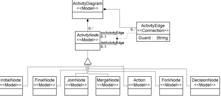
Figure 2: Meta-model for UML Activity Diagrams
2.3 UML to CSP Transformation
case study here from a GReAT point of view, and we will use this as an example to explain our technique for verifying model transformations.
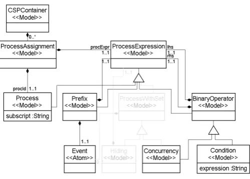
The objective of this transformation is to take a UML Activity Diagram [OMG06] and generate a Communicating Sequential Process [Hoa78] model with the equivalent behavior. The Activity Diagram consists of various types ofActivity Nodes, which can be connected by directedActivity Edges. Figure2shows the GME meta-model for UML Activity Diagrams. A CSPProcess is defined by aProcess Assignment, which assigns aProcess Expressionto aProcess Id. Process Expressionscan be a simpleProcess, aPrefixoperator or aBinaryOperator. Figure3shows the GME meta-model for CSP, highlighting the relevant parts for our example.
Figure 3: Meta-model for CSP
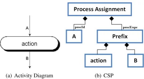
The UML to CSP mapping assigns aProcessfor eachActivity Edge. For each type ofActivity Node, aProcess Assignmentis created, which assigns the Process corresponding to the incoming Activity Edge to aProcess Expressiondepending on the type of the Activity Node. Figure 4
shows one such mapping, for the type Action Node. This assigns the incoming Process to a Prefixexpression. The resulting CSP expression can be written as A=action−→B, which is shown in Figure4as a model instance compliant with the CSP meta-model.
3
Structural Correspondence
As in the UML to CSP case, model transformations can be used to generate a target model of a certain structure (CSP) from a source model of a different structure (UML). Specific structural configurations in the source model (such as anAction Nodein the UML model) produce specific structural configurations in the target model (such as aPrefix in the CSP model). The rules to accomplish the structural transformations may be simple or complicated. However, it is fairly straightforward to compare and verify that the correct structural transformation was made, if we already know which parts of the source structure map to which parts of the target structure.
(a) Activity Diagram (b) CSP
Figure 4: CSP Process Assignment for Action Node
a set of structural correspondence rules specific to a certain transformation. We will then use cross-links to trace source elements with the corresponding target elements, and finally use these cross-links to check whether the structural correspondence rules hold.
In essence, we expect that the correspondence conditions are independently specified for a model transformation, and an independent tool checks if these conditions are satisfied by the instance models, after the model transformation has been executed. In other words, the corre-spondence conditions depend purely on the source and target model structures and not on the rewriting rules necessary to effect the transformation. Since the correspondence conditions are specified in terms of simple queries on the model around previously chosen context nodes, we expect that they will be easier to specify, and thus more reliable than the transformation itself. We also assume that the model transformation builds up a structure for bookkeeping the mapping between the source and target models.
3.1 Structural Correspondence Rules for UML to CSP Transformation
A structural correspondence rule is similar to a precondition-postcondition style axiom. We will construct them in such a way that they can be evaluated easily on model instances. We will use the UML to CSP example to illustrate structural correspondence. Consider the case for the Action Node, as shown in Figure4. TheAction Nodehas one incoming edge and one outgoing edge. It is transformed into aProcess Assignmentin the CSP. The CSP structure for this instance consists of aProcess Idand aPrefix, with anEvent and a targetProcess. This is the structural transformation for each occurrence of an Action Node in the Activity Diagram.
Rule Path expression
TheAction Nodecorresponds to a
Process Assignment with a Prefix PA.procExpr.type=Pre f ix The incoming edge in the UML
corresponds to the Process Id AN.inEdge.name=PA.procId.name The outgoing edge corresponds to
the target Process AN.outEdge.name=PA.procExpr.Process.name Theactionof the Action Node
corresponds to the Event AN.action=PA.procExpr.event
Table 1: Structural Correspondence Rules for Action Node
These rules together specify the complete structural correspondence for a section of the Ac-tivity Diagram and a section of its equivalent CSP model. The different types of AcAc-tivity Nodes result in different structures in the CSP model, some of which are more complex than the fairly straightforward case for the Action Node. Next, we look at the structural mapping for some of the other nodes.
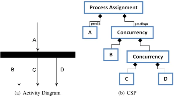
AFork Nodein the Activity Diagram is transformed into a Process Assignment with a Con-currencyExpression. Figure5shows a Fork Node with an incoming edgeAand three outgoing edgesB,CandD. This is represented by the CSP expressionA=Bk(CkD), wherekrepresents concurrency (the actual ordering ofB,CandDis immaterial). The structural representation of this expression as an instance of the CSP meta-model is shown in Figure5. The Fork Node is transformed into a CSP Process Assignment that consists of a Process Id corresponding to the incoming Activity Edge of the Fork Node, and a Process Expression of typeConcurrency. The Concurrency Expression consists of Processes and other Concurrency nodes, depending on the number of outgoing Activity Edges.
If we denote the Fork Node byFN and the Process Assignment byPA, the structural
corre-(a) Activity Diagram (b) CSP
Rule Path expression
TheFork Nodecorresponds to a
Process Assignment with a Concurrency PA.procExpr.type=Concurrency The incoming edge in the UML
corresponds to the Process Id FN.inEdge.name=PA.procId.name For each outgoing edge, ∀o∈FN.outEdge
there is a corresponding Process ∃p∈PA.procExpr..Process:o.name=p.name in the Process Expression
Table 2: Structural Correspondence Rules for Fork Node
(a) Activity Diagram (b) CSP
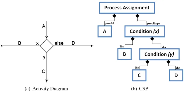
Figure 6: CSP Process Assignment for Decision Node
spondence rules can be described using path expressions as shown in Table2. We will use the double-dot ‘..’ to denote thedescendantoperator (similar to ‘//’ in XPath queries), to specify ancestor-descendant relationships.
By evaluating these rules on the Activity Diagram and the CSP models, we can determine whether the structural correspondence was satisfied for Fork Nodes. Another type of node in the Activity Diagram is theDecision Node. The transformation mapping for the Decision Node is a slight variation of the Fork Node. Figure6shows a Decision Node with an incoming edgeA, and three outgoing edgesB,CandD, with guardsx,yandelserespectively (in this case study, we will assume that the Decision Node always has exactly one ‘else’ edge). This is represented by the CSP expressionA=B6<x6>(C6<y6>D), where the operatorC6<y6>Dis thecondition operator with the meaning that ifyistrue, then the process behaves likeC, else likeD.
Rule Path expression
TheDecision Nodecorresponds to a
Process Assignment with a Condition PA.procExpr.type=Condition The incoming edge in the UML
corresponds to the Process Id DN.inEdge.name=PA.procId.name For each outgoing edge, there is
a corresponding Condition in the ∀o∈DN.outEdge∧o.guard6=else Process Expression and a corresponding ∃c∈PA.procExpr..Condition:
Process in the Condition’s LHS c.expression=o.guard∧c.lhs.name=o.name For the outgoing ‘else’ edge,
there is a Condition in the ∀o∈DN.outEdge∧o.guard=else Process Expression with a ∃c∈PA.procExpr..Condition: corresponding Process as it’s RHS c.rhs.name=o.name
Table 3: Structural Correspondence Rules for Decision Node
structural correspondence rules for this mapping are shown in Table3.
3.2 Specifying Structural Correspondence Rules in GReAT
Specifying the structural correspondence for a transformation consists of two parts:
1. Identifying the significant source and target elements of the transformation
2. Specifying the structural correspondence rules for each element using path expressions
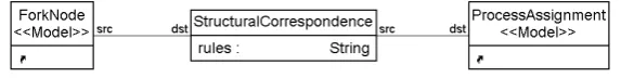
The first step is accomplished in GReAT by using cross-links between the source and target elements. A composite meta-model is added to the transformation, by associating selected source and target elements using a temporary ‘Structural Correspondence’ class. There will be one such class for each pair of elements. This class will have a string attribute, which is set to the path expressions necessary for structural correspondence for that pair. Figure 7 shows a composite meta-model specifying the structural correspondence for Fork Nodes. TheFork Node class comes from the Activity Diagram meta-model, and theProcess Assignment class comes from the CSP meta-model.
Figure 7: Composite Meta-model to Specify Structural Correspondence
Once the structural correspondence has been specified for all the relevant items, the transfor-mation is enhanced to create the cross-link when creating the respective target elements. Figure8
Figure 8: GReAT Rule with Cross-link for Structural Correspondence
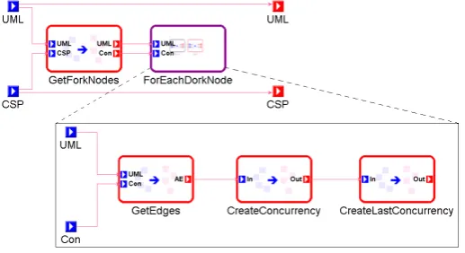
create the cross-link for structural correspondence. Note that in incoming Activity Edge is rep-resented as anAssociation ClassnamedActivityEdgeIn. The transformation for the Fork Node is actually accomplished in a sequence of several rules executed recursively, as shown in Figure9. First all the Fork Nodes are collected, and a sequence of rules are executed for each node. These rules iterate through the out-edges of each Fork node, creating the Concurrency tree. Though several rules are involved in the transformation for Fork nodes, the cross-link needs to be added to one rule only.
It must be noted that it is necessary to specify the structural correspondence rules only once in the composite meta-model. The cross-link must however be added to the transformation rules, and in most cases will be required only once for each pair of source and target element.
3.3 Evaluating the Structural Correspondence Rules
Once the structural correspondence rules have been specified, and the cross-links added to the transformation, the correspondence rules are evaluated on the instance models after each execu-tion of the transformaexecu-tion. These rules can be evaluated by performing a simple depth first search on the instance models, and checking if the correspondence rules are satisfied at each relevant stage.
Figure 9: Sequence of GReAT Rules for Fork Node Transformation
time the structural correspondence specification changes. The second phase is to call the model traverser code at the end of each execution of the transformation, supplying to it the source and target model instances along with the cross-links.
In the case of the UML to CSP transformation, we traverse the input Activity Diagram model and evaluate the correspondence rules at each activity node. For each Activity Node, the cross-link is traversed to find the corresponding Process Assignment. If a correspondence rule has been defined for an Activity Node, and no corresponding Process Assignment is found, then this signals an error in the transformation. After locating the corresponding Process Assignment, the path expressions are evaluated. If any of the rules are not satisfied, the error is reported. If all the rules are satisfied for all the nodes, then we can conclude that the transformation has executed correctly.
The instance model is traversed in a depth-first manner. The corresponding elements are located using the cross-links, which will take constant time. The path expressions are evaluated on the instances, which will take polynomial time in most cases. Thus, the overall verification process does not incur a significant performance overhead in most cases.
3.4 Remarks
The structural correspondence based verification described here can provide important assur-ances about the correctness of transformations, while being practically applicable in most com-mon transformations.
The use of path expressions to specify correspondence rules makes it easy to specify cor-rectness. The path expressions use a simple query language that can be easily evaluated on the instance models. Our future research concentrates on the requirements of such a query language. Most complex transformations may involve multiple rules executing recursively to transform a particular part of a model. However, it may be possible to specify the correspondence for that part of the model using a set of simple path expressions. Such a specification would be simpler and easier to understand than the complex transformation rules.
Thus, these rules may be written by someone other than the original transformation writer, or even supplied along with the requirements document.
4
Related Work
[K¨04], [KHE03] present ideas on validating model transformations. In [KHE03], the authors present a concept of rule-based model transformations with control conditions, and provide a set of criteria to ensure termination and confluence. In [K¨04], K¨uster focuses on the syntactic correctness of rule-based model transformations. This validates whether the source and target parts of the transformation rule are syntactically correct with respect to the abstract syntax of the source and target languages. These approaches are concerned with the functional behavior and syntactic correctness of the model transformation. [LT] also discusses validation of transforma-tions on these lines, but also introduces ideas of syntactic consistency and behavior preservation. Our technique addresses semantic correctness of model transformations, addressing errors intro-duced due to loss or mis-representation of information during a transformation.
In [BH07], Bisztray and Heckel present a rule-level verification approach to verify the seman-tic properties of business process transformations. CSP is used to capture the behavior of the processes before and after the transformation. The goal is to ensure that every application of a transformation rule has a known semantic effect. We use path expressions to capture the relation between structures before and after a transformation. These path expressions are generic (they do not make any assumptions about the underlying semantics of the models involved), and can be applied to a wide variety of transformations.
Ehrig et. al. [EEE+07] study bidirectional transformations as a technique for preserving in-formation across model transin-formations. They use triple graph grammars to define bi-directional model transformations, which can be inverted without specifying a new transformation. Our ap-proach offers a more relaxed framework, which will allow some loss of information (such as by abstraction), and concentrates on the crucial properties of interest. We also feel that our approach is better suited for transformations involving multiple models and attribute manipulations.
In other related work, [VP03] presents a model level technique to verify transformations by model checking a selected semantic property on the source model, and transforming the property and validating it in the target domain. The validation requires human expertise. After transform-ing the property, the target model is model checked. In our approach, since the properties are specified using cross links that span over both the source and target languages, we do not need to transform them. [LLMC06] discuss an approach to validate model transformations by applying OCL constraints to preserve and guarantee certain model properties. [GGL+06] is a language level verification approach which addresses the problem of verifying semantic equivalence be-tween a model and a resulting programming language code.
4.1 MOF QVT Relations Language
Relations may be specified over two or more domains, with a pair ofwhenandwherepredicates. The whenpredicate specifies the conditions under which a relation must hold, and the where predicate specifies the condition that all the participating model elements must satisfy. Addition-ally, relations can be marked ascheckonlyorenforced. If it is markedcheckonly, the relation is only checked to see if there exists a valid match that satisfies the relationship. If it is marked enforced, the target model is modified to satisfy the relationship whenever the check fails.
Our approach can be likened to thecheckonlymode of operation described above. However, in our case, the corresponding instances in the models are already matched using cross links, and the correspondence conditions are evaluated using their context. The cross links help us to avoid searching the instances for valid matches. Specifying the correspondence conditions using context nodes simplifies the model checking necessary to evaluate the conditions, thus simplifying the verification process. Since we verify the correspondence conditions for each instance generated by the transformation, these features play an important role.
4.2 Triple Graph Grammars
Triple Graph Grammars [Sch95] are used to describe model transformations as the evolution of graphs by applying graph rules. The evolving graph complies with a graph schema that consists of three parts. One graph schema represents the source meta model, and one represents the target meta-model. The third schema is used to track correspondences between the source and target meta models. Transformations are specified declaratively using triple graph grammar rules, from which operational rules are derived to effect model transformations.
The schema to track correspondences between the source and target graphs provides a frame-work to implement a feature similar to cross links in GReAT. If the correspondence rules can be encoded into this schema, and the correspondence links persisted in the instance models, our verification approach can be implemented in this scenario.
5
Conclusions and Future Work
In this paper, we have shown how we can provide an assurance about the correctness of a trans-formation by using structural correspondence. The main errors that are addressed by this type of verification is the loss or misrepresentation of information during a model transformation.
We continue to hold to the idea that it is often more practical and useful to verify transfor-mations on an instance basis. The verification framework must be added to the transformation only once, and is invoked for each execution of the transformation. The verification process does not add a significant overhead to the transformation, but provides valuable results about the correctness of each execution.
The path expressions must use a simple and powerful query language to formulate queries on the instance models. While existing languages such as OCL may be suitable for simple queries, we may need additional features, such as querying children to an arbitrary depth. Our future research concentrates on the requirements of such a language.
rules. However, in most cases, it may be possible to infer where the cross-links must be placed. If the cross-links could be inserted into the rules automatically, the transformation can remain a black box. The main concern with this is that the cross-links are crucial to evaluating the correspondence rules correctly and also to keep the complexity down.
We have seen simple string comparisons added to the path expressions in this paper. Some transformations may require more complex attribute comparisons, or structure to attribute com-parisons such as counting. We wish to explore such situations in further detail in future cases, to come up with a comprehensive language for specifying the path expressions.
Acknowledgement
The research described in this paper has been supported by a grant from NSF/CSR-EHS, titled “Software Composition for Embedded Systems using Graph Transformations”, award number CNS-0509098.
Bibliography
[AKL03] A. Agrawal, G. Karsai, A. Ledeczi. An end-to-end domain-driven software develop-ment framework. InOOPSLA ’03: 18th annual ACM SIGPLAN conference on OOP, systems, languages, and applications. Pp. 8–15. ACM Press, New York, NY, USA, 2003.
doi:http://doi.acm.org/10.1145/949344.949347
[BEH07] D. Bisztray, K. Ehrig, R. Heckel. Case Study: UML to CSP Transformation. In Applications of Graph Transformation with Industrial Relevance (AGTIVE). 2007.
[BH07] D. Bisztray, R. Heckel. Rule-Level Verification of Business Process Transformations using CSP. InProceedings of the 6th International Workshop on Graph Transfor-mation and Visual Modeling Techniques (GT-VMT’07). 2007.
[LT] de Lara, J. and Taentzer, G. Automated Model Transformation and its Validation with AToM3 and AGG. InLecture Notes in Artificial Intelligence, 2980. Pp. 182– 198. Springer.
[DF05] E. Denney, B. Fischer. Certifiable Program Generation. In Gl¨uck and Lowry (eds.), GPCE. Lecture Notes in Computer Science 3676, pp. 17–28. Springer, 2005.
[EEE+07] H. Ehrig, K. Ehrig, C. Ermel, F. Hermann, G. Taentzer. Information Preserving Bidi-rectional Model Transformations. In Fundamental Approaches to Software Engi-neering. Pp. 72–86. 2007.
doi:http://dx.doi.org/10.1007/978-3-540-71289-3 7
[GGL+06] H. Giese, S. Glesner, J. Leitner, W. Schfer, R. Wagner. Towards Verified Model Transformations. October 2006.
[Hol97] G. J. Holzmann. The Model Checker SPIN.IEEE Trans. Softw. Eng.23(5):279–295, 1997.
doi:http://dx.doi.org/10.1109/32.588521
[K¨04] J. M. K¨uster. Systematic Validation of Model Transformations. InProceedings 3rd UML Workshop in Software Model Engineering (WiSME 2004). October 2004.
[KHE03] J. M. K¨uster, R. Heckel, G. Engels. Defining and validating transformations of UML models. InHCC ’03: Proceedings of the 2003 IEEE Symposium on Human Centric Computing Languages and Environments. Pp. 145–152. IEEE Computer Society, Washington, DC, USA, 2003.
[LBM+01] A. Ledeczi, A. Bakay, M. Maroti, P. Volgyesi, G. Nordstrom, J. Sprinkle, G. Karsai. Composing Domain-Specific Design Environments.Computer34(11):44–51, 2001.
doi:http://dx.doi.org/10.1109/2.963443
[LLMC06] L. Lengyel, T. Levendovszky, G. Mezei, H. Charaf. Model-Based Development with Strictly Controlled Model Transformation. In The 2nd International Workshop on Model-Driven Enterprise Information Systems, MDEIS 2006. Pp. 39–48. Paphos, Cyprus, May 2006.
[MV05] T. Mens, P. Van Gorp. A taxonomy of model transformation. InProc. Int’l Workshop on Graph and Model Transformation. 2005.
[NK06] A. Narayanan, G. Karsai. Towards Verifying Model Transformations. In Bruni and Varro (eds.),Graph Transformation and Visual Modeling Techniques GT-VMT 2006. Electronic Notes in Theoretical Computer Science, pp. 185–194. 2006.
[OMG05] OMG. Meta Object Facility (MOF) 2.0 Query/View/Transformation Specification. 2005.http://www.omg.org/cgi-bin/doc?ptc/2005-11-01.
[OMG06] OMG. Unifed Modeling Language, version 2.1.1. 2006.
”http://www.omg.org/technology/documents/formal/uml.htm”
[San04] D. Sangiorgi. Bisimulation: From The Origins to Today. In LICS ’04: Proceed-ings of the 19th Annual IEEE Symposium on Logic in Computer Science (LICS’04). Pp. 298–302. IEEE Computer Society, Washington, DC, USA, 2004.
doi:http://dx.doi.org/10.1109/LICS.2004.13
[Sch95] A. Sch¨urr. Specification of Graph Translators with Triple Graph Grammars. InWG ’94: Proceedings of the 20th International Workshop on Graph-Theoretic Concepts in Computer Science. Pp. 151–163. Springer-Verlag, London, UK, 1995.