Available online throug
ISSN 2229 – 5046
STUDY OF EFFECT OF POROSITY IN THE PRESENCE
OF APPLIED MAGNETIC FIELD A COSINE FORM CONVEX CURVED PLATE MODEL
SYED ARISHIYA NASEEM FATIMA*
1, TRIMBAK BIRADAR
2, S.T FATHIMA
3AND HANUMAGOWDA B.N
41
Department of Mathematics,
K.C.T College of Engineering, Gulbarga-585104, India.
2
Department of Mathematics,
Sharnbasveshwar College of science, Gulbarga-585103.
3
Ashford, West Monroe, Luisiana, USA-71291.
4
Department of Mathematics, Reva University, Bangalore-560064, India.
(Received On: 07-09-16; Revised & Accepted On: 30-09-16)
ABSTRACT
T
he study of effect of porosity in the presence of applied magnetic field is studied in case of cosine form convex curved plates. The magneto‐hydrodynamic (MHD) Reynolds‐type equation for convex curved plates is derived using the continuity equation and the MHD motion equations. According to the results obtained, the presence of applied magnetic field signifies an increase in the MHD pressure. Compared with the classical non‐magnetic case, the magnetic‐field effect characterized by the Hartmann number provides an enhancement to the MHD load‐carrying capacity and the response time for the porous convex curved plates. It is observed that effect of porosity is to decrease the performance characteristics of the Cosine form convex curved plate model.Keywords: convex curved plates,cosine function, porous medium, Magnetic field.
1. INTRODUCTION
In recent years, the characteristic of Magneto-hydrodynamics (MHD) in flow analysis are important for many engineering and industrial applications. The MHD bearings with conducting fluids possess the high thermal-conductivity and high electrical-thermal-conductivity features over the conventional bearings [1-9].The squeeze film lubrication for different configuration of bearings under the action of transverse magnetic field has been discussed by several authors [10-15].Magneto hydrodynamic flow has many applications in aerodynamic heating, electrostatic precipitation, polymer technology, petroleum industry, accelerators, fluid droplets, MHD pumps, power generators and purification of crude oil. Flow through porous medium has numerous engineering and geophysical applications.
Self-lubricating porous bearings have been studied in the last few decades because of their industrial applications and machine manufacturing. These bearings have self-contained oil reservoir and hence do not require continuous lubrication. Most porous bearings have interconnecting pores which store the lubricating fluid. When the normal load is applied, the fluid is supplied through the interconnected pores to the fluid film region to support the load, and when the load is removed from the loaded zone of the bearing, fluid is reabsorbed by capillary action. Since these can operate without additional lubricant for longer period, porous bearings have been used widely, where re-lubrication would be difficult. Thus, porous metal bearings have been used in the manufacturing of vehicles, home appliances, machines, and so forth. Because of the importance of porous bearings, Wu [16] studied the squeeze film effects between two rectangular plates in which both plates have a porous material. Numerous papers are available in the literature for the study of different types of porous bearings for example, journal bearings [17], slider bearings [18], thrust bearings [19], and many more.
Corresponding Author: Syed Arishiya Naseem Fatima*
1The study of porosity in the presence of applied magnetic field considering cosine form convex curved plate model has not been studied so far. Hence, in this paper an attempt has been made to study the effect of porosity in the presence of applied magnetic field in case of Cosine form convex curved plates. Modified Reynolds equation is obtained using Darcy’s law for porous media and expressions for the MHD pressure, load carrying capacity and the time height relation are obtained.
2. MATHEMATICAL FORMULATION OF THE PROBLEM
Figure-1: The physical configuration of convex curved - plates mode in the presence of transverse magnetic field.
Figure.1 shows the squeeze film geometry between the cosine form convex curved plates. The lower plate with a
porous facing of thickness
δ
is fixed and the upper plate has a squeezing velocitydh
dt
is approaching the lowerplate under a constant load. The film thickness
h
for the squeeze film can be generated by the form of a cosine function0
1 cos
h
h
d
x
L
π
=
+
−
. In the equation,L
is the length of the plates, d is the amplitude of the cosinefunction, and
h
0is the minimum film thickness. At the central position:x
=
0
, the film thickness is equal to theminimum film thickness
h
0. At the edge position:2
L
x
=
, the film thickness is equal to the sum of the minimum filmthickness and the amplitude
h
0+
d
.A uniform transverse magnetic fieldB
0 is applied to the bearing in thez
−
direction as shown in the above figure1.It is assumed that the fluid film is thin, the body forces and the body couples are negligible. Under these assumptions, the hydrodynamic lubrication theory applicable to thin films, the continuity equation and the MHD governing equations of motion in rectangular coordinate are2 2
0
2 2
0
1
u
M
p
u
z
h
µ
x
∂
−
=
∂
∂
∂
(1)0
p
z
∂
=
∂
(2)0
u
w
x
z
∂
+
∂
=
∂
∂
(3)Where 0
0
M
M
h
=
andM
0B h
0 0( )
σ
1/ 2µ
=
is the Hartmann number.The relevant boundary conditions for the velocity components are i) At the upper surface
z
=
h
ii) At the lower surface
z
=
0
u
=
0
(
no Slip
)
*
w
=
w
(5)Where
w
* is the modified Darcy velocity component in thez
−
direction in the porous region. Modified form of the Darcy law for porous material is given by* * 2 0 2 0
1
k
p
u
x
kM
mh
µ
∂
= −
∂
+
(6) **
k p
w
z
µ
∂
= −
∂
(7) Wherek
is the permeability of porous matrix,m
porosity andp
*is the pressure in the porous region.The solution of equation (1) subject to the boundary conditions eqns. (4) and (5) is given by
2
(
)
2sinh
sinh
1
2
2
cosh
2
Mz
M z
h
p
u
Mh
M
x
µ
−
∂
=
∂
(8)Substituting above value of
u
in the integral form of continuity equation:0 0
0
h
h
udz
w
w
x
∂
+
−
=
∂
∫
(9)Substituting equations (6) and (7) in the following continuity equation for lower porous region
* *
0
u
w
x
z
∂
+
∂
=
∂
∂
(10)Integrating above equation once with respect to
z
from−
δ
to0
and using the Morgan-Cameron approximation with the condition∂
p
*∂ =
z
0
whenz
= −
δ
gives* 2
2 2 0
z
p
p
z
c
x
δ
=
∂
= −
∂
∂
∂
(11)where 2 2 0 2 0
1
kM
c
mh
=
+
andδ
is the thickness of the porous layer.Substituting (8) and (11) in (9) gives
3 2
1
2
2
p
Mh
k
p
Mh
tanh
V
x
M
x
c
x
δ
µ
µ
∂
∂
−
+
∂
= −
∂
∂
∂
(12) Introducing the dimensionless quantities3
* * * 0 *
2 3
0 0 0 0
,
,
,
,
,
(
/
)
ph
x
h
d
k
x
h
P
A
L
h
L dh dt
h
h
h
δ
δ
ψ
δ
µ
=
=
= −
=
=
=
Equation (12) takes the form *
* 0
* *
( ,
, )
1
P
F h M
x
x
ψ
∂ ∂
= −
∂
∂
(13)Where
*
* * 0
0 3 0 2
0
1
( ,
, )
2
2
M h
F h M
M h
tanh
M
C
ψ
ψ
=
−
+
, 2 2 0 *1
M
C
m
ψ
δ
=
+
and{
}
*
1
*.
1 cos(
)
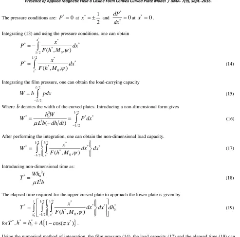
The pressure conditions are:
P
*=
0
at *1
2
x
= ±
and **
0
dP
dx
=
at*
0
x
=
.Integrating (13) and using the pressure conditions, one can obtain *
*
* *
* 0 1 / 2
( ,
, )
x
x
P
dx
F h M
ψ
= −
∫
*
1/ 2 *
* * * 0
( ,
, )
xx
P
dx
F h M
ψ
=
∫
(14)Integrating the film pressure, one can obtain the load-carrying capacity / 2
/ 2 L
L
W
b
pdx
−
=
∫
(15)Where
b
denotes the width of the curved plates. Introducing a non-dimensional form gives 1/ 23
* 0 * *
3
1/ 2
(
)
h W
W
P dx
L b
dh dt
µ
−=
=
−
∫
(16)After performing the integration, one can obtain the non-dimensional load capacity.
* 1/ 2
1/ 2 *
*
* *
* 0 1/ 2 x
(
,
, )
x
dx
W
dx
F h M
ψ
−
=
∫
∫
(17)Introducing non-dimensional time as: 2 * 0 3
Wh t
T
L b
µ
=
(18)The elapsed time required for the upper curved plate to approach the lower plate is given by
* *
0
1/ 2
1 1/ 2 *
*
* * *
0 *
0 1/ 2 x
(
,
, )
hx
dx
T
dx dh
F h M
ψ
−
=
∫
∫ ∫
(19)for
T
*,h
*=
h
0*+
A
{
1 cos(
−
π
x
*)
}
.Using the numerical method of integration, the film pressure (14), the load capacity (17) and the elapsed time (19) can be calculated.
3. RESULTS AND DISCUSSIONS
The effect of porosity on cosine form convex curved plates in the presence of magnetic field is observed and the squeeze film characteristics are analysed with respect to the non-dimensional parameters namely the Hartmann number
0
M
and permeability parameterψ
.All required characteristic features of squeeze film bearings such as the pressure distribution, load-carrying capacity, and squeezing time have been obtained as functions of dimensionless Hartmannnumber
M
0 and permeability parameterψ
.3.1. Squeeze film pressure
Figure 2, 3 represents the variation of non-dimensional pressure
P
* with horizontal coordinatex
* for different values ofψ
andM
0 . These figures show the effect of magnetic field in terms of pressure distribution when other parametersare held fixed. It is observed that the pressure distribution increases for increasing values of
M
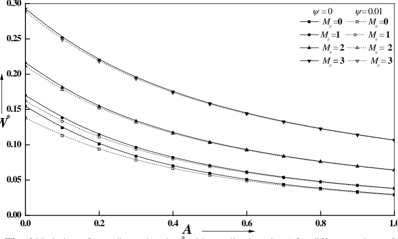
0 compared to3.2. Load carrying capacity
Figure 4, 5 shows the variation of non-dimensional
W
* with amplitude ratioA
for different values ofψ
andM
0. It is clearly observed from this figure that the load capacity increases for increasing magnetic number compared to0
0
M
=
. For increasing values ofM
0, pressure distribution increases in the fluid region, hence, load capacity also increases. The effects are more distinct in convex curved plates in presence of transverse magnetic field. The increasein
W
*is more evident for larger values ofM
0.3.3. Non-dimensional Squeeze film time
Figure 6, 7, 8 represents Variation of non-dimensional squeeze film time
T
* withh
0* for different values ofM
0 and.
ψ
The response times of convex curved porous squeeze films are significantly extended in the presence of external magnetic field. As magnetic parameter increases, the squeeze film time also increases. The applied magnetic field strongly opposes the fluid flow in the film region which retains large number of fluid in the film region. Thus, there is significant increase in squeezing time.Table.1-Illustrates the effect of transverse magnetic field on the squeeze film characteristics, and is evaluated by the relative percentage difference. The relative variation of load capacity and the approaching time of porous convex curved squeeze films is tabulated, and it is observed that the performance characteristics are improved for higher values
of magnetic parameter
M
0. The increase in the non-dimensional load carrying capacity * WR
and non-dimensionalsqueeze film time
R
T* are defined by *{
(
)
}
* * *
100
magnetic non magnetic non magnetic W
R
=
W
−
W
−W
−×
And *
{
(
)
}
* * *
100
magnetic non magnetic non magnetic T
R
=
T
−
T
−T
−×
The values of W
R
∗ andT
R
∗are listed in Table. 1 for various values ofM
0andψ
.4. CONCLUSION
The study of effect of porosity on the performance characteristics of cosine form convex curved plates in the presence of magnetic field is studied. The squeeze film characteristics for porous convex curved plates are improved in presence of external magnetic fields i.e, the load carrying capacity and squeeze film time increases for increasing values of
magnetic parameter
M
0 . It is observed that the pressure distribution, load-carrying capacity, and squeeze time increases for increasing values of Hartmann number, It is observed that effect of porosity on the permeability of cosine form convex curved is found to decrease these effects.Nomenclature:
0
B
applied magnetic field in the
z
−
directionL
length of the platesd
amplitude of the cosine functionb
width of the curved platesA
amplitude ratio of the cosine-form convex curved plates0
h
minimum film thickness
0
h
∗ dimensionless film thickness after time∆
t
k
permeability of the porous matrixp
hydrodynamic film pressure*
p
pressure in the porous region0
M
Magnetic ParameterB h
0 0( )
σ
1/ 2µ
=
,
u v
Velocity components in film region *,
x z
local Cartesian co-ordinatesm
porosity*
P
dimensionless pressure�3 0 2
(
/
)
ph
L
dh dt
µ
=
−
�t
mean time of approachT
∗ Dimensionless time of approach� 2 0 3h Wt
L b
µ
=
�V
Squeezing Velocitydh
dt
−
*
W
Dimensionless load carrying capacity� 03 3(
)
h W
L b
dh dt
µ
=
−
�Greek symbols
σ
Conductivity of fluidψ
nondimensional permeability parameterδ
thickness of the porous layer*
δ
dimensionless thickness of the porous layerµ
lubricant viscosityREFERENCES
[1]. Hays, D.F., “Squeeze Films for Rectangular Plates,” ASME Journal of Basic Engineering, Vol. 85, (1963), pp. 243-246.
[2]. Murti, P.R.K., “Squeeze Films in Curved Circular Plates,” ASME Journal of Lubrication Technology, Vol. 97, (1975), pp. 650-652.
[3]. Pinkus, O., and Sternlicht, B., Theory of Hydrodynamic Lubrication, McGraw Hill, New York (1961).
[4]. Lin, J.R., “Pure Squeeze Film Behavior in a Hemispherical Porous Bearing Using the Brinkman Model,” STLE Tribology Transactions, Vol. 39, (1996), pp. 769-778.
[5]. Hamrock, B.J., Fundamentals of Fluid Film Lubrication, McGraw-Hill, New York (1994).
[6]. Lin, J.R., Liao, W.H. and Hung, C.R., “The Effects of Couple Stresses in the Squeeze Film Characteristics between a Cylinder and a Plane Surface,” Journal of Marine Science and Technology, Vol. 12, (2004), pp. 119-123.
[7]. Lin, J.R., “Squeeze Film Characteristics between a Sphere and a Flat Plate: Couple Stress Fluid Model,” Computers and Structures, Vol. 75, (2000), pp. 73-80.
[8]. Barus, C., “Isothermals, Iopiestics, and IometricsRlative to Viscosity,” American Journal of Science, Vol. 45,(1893), pp. 87-96.
[9]. Lu, R.F. and Lin, J.R., “A Theoretical Study of Combined Effects of Non Newtonian Rheology and Viscosity-pressure Dependence in the Sphere-plate Squeeze-film system,” Tribology International, Vol. 40, (2007), pp. 125-131.
[10].W.F.Hughes, “The magnetohydrodynamic Finite Step Slider bearing,” Journal of fluids engineering, Trans. ASME, series D, vol.85, no.1, (1963), pp.129-135.
[11].W. F. Hughes and R. A. Elco, “MHD lubrication flow between parallel rotating disks, ”Journal of Fluid Mechanics, vol. 13, no.1,(1962), pp. 21-32.
[12].D.C. Huzma, “The Magneto-hydrodynamic parallel slider bearing,” Journal of Fluids engineering, Trans. ASME, series D, vol.87, (1965), pp.778-780.
[13].D. C.Kuzma, E. R. Maki ,and R. J.Donnely, “The MHD squeeze film,” Journal of Fluid Mechanics, vol.19, no. 3, (1964), pp. 395-400.
[14].W. F.Huges and R.J. Elco, “Magnetohydrodynamic journal bearing,” Journal of American Rocket society, vol.32, (1962), pp.776-778.
[15].J. R .Lin, “Magneto-hydrodynamic squeeze film characteristics between annular plates,” Industrial Lubrication and Tribology, Vol. 53, no. 2, (2001), pp.66 - 71.
[16].H.Wu, “Analysis of the squeeze film between porous rectangular plates,” Journal of Lubrication Technology, vol. 94, no. 1, (1972), pp. 64–68.
[18].U. Srinivasan, “The analysis of a double-layered porous slider bearing,” Wear, vol.42, no. 2, (1977), pp. 205– 215.
[19].R. S. Gupta and V. K. Kapur, “Centrifugal effects in hydrostatic porous thrust bearings,” Journal of Lubrication Technology, vol. 101, no. 3, (1979), pp. 381– 392.
-0.5 -0.4 -0.3 -0.2 -0.1 0.0 0.1 0.2 0.3 0.4 0.5
0.0 0.2 0.4 0.6 0.8 1.0 1.2 1.4 1.6 1.8 2.0
P
*
x
*Fig.2 Variation of non-dimensional P* with x*
for different values of
ψ
and M0with
δ=0.01
ψ =0 ψ =0.01
M0=0 M0=0 M0=1 M0=1 M0=2 M0=2 M0=3 M0=3
-0.5 -0.4 -0.3 -0.2 -0.1 0.0 0.1 0.2 0.3 0.4 0.5
0.0 0.2 0.4 0.6 0.8 1.0 1.2 1.4 1.6 1.8 2.0
P
*
x
*Fig.3 Variation of non-dimensional P* with x*for different values of
ψ
and M0with δ=0.01M0=0 M0=3
ψ =0.0 ψ =0.0
ψ =0.001 ψ =0.001
ψ =0.01 ψ =0.01
ψ =0.1 ψ =0.1
0.0 0.2 0.4 0.6 0.8 1.0 0.00
0.05 0.10 0.15 0.20 0.25 0.30
ψ = 0 ψ = 0.01
M
0 =0 M0 =0
M0 =1 M0 = 1 M0 = 2 M0 = 2 M0= 3 M0 = 3
A
W
*Fig. 4
Variation of non-dimensional
W
*with amplitude ratio
A
for different values of
ψ
and
M
0.
0.0 0.1 0.2 0.3 0.4 0.5 0.6 0.7 0.8 0.9 1.0
0.00 0.05 0.10 0.15 0.20 0.25 0.30
W
*
A
Fig.5
Variation of non-dimensional
W
*with
A
for different values of
ψ
and
M
0
with
δ
=
0.01
0.2 0.3 0.4 0.5 0.6 0.0
0.5 1.0 1.5 2.0 2.5 3.0 3.5
ψ = 0 ψ = 0.01
M0 = 0 M0 = 0 M0 = 1 M0 = 1
M0 = 2 M0 = 2 M0 = 3 M0 = 3
h
*0T
*Fig. 6
Variation of non-dimensional
T
with
h
*0for different values of
ψ
and
M
0
at A=0.2.
0.2 0.3 0.4 0.5 0.6 0.7 0.8 0.9 1.0
0.0 0.5 1.0 1.5 2.0 2.5 3.0 3.5 4.0 4.5 5.0 5.5
M0 = 0 M0= 3
A= 0.1 A = 0.1 A= 0.2 A = 0.2 A= 0.3 A = 0.3
h
*0T
*Fig. 7
Variation of non-dimensional
T
*with
h
*0for different values of
0.2 0.3 0.4 0.5 0.6 0.7 0.8 0.9 1.0 0
1 2 3 4 5 6
T
*
h
0*Fig.8
Variation of non-dimensional
T
*with
h
0*for different values of
ψ
and
M
0with
A=0.1 and
δ
=
0.01
M0=0 M0=3 ψ=0.0 ψ=0.0 ψ=0.001 ψ=0.001 ψ=0.01 ψ=0.01 ψ=0.1 ψ=0.1 ψ=1 ψ=1
Table-1: Variation of W
R
∗andR
T* for different values ofM
0,ψ
,δ
=
0.01
andm
=
0.6
* W
R
R
T*ψ
=0.0 0M
=1 18.7857 3.31690
M
=2 74.7225 13.2480
M
=3 166.6498 29.753ψ
=0.01 0M
=1 21.896 35.3440
M
=2 81.144 68.8780
M
=3 177.246 101.258ψ
=1 0M
=1 548.387 4644.480
M
=2 873.719 6423.340
M
=3 1391.84 7747Source of support: Nil, Conflict of interest: None Declared