Sharif University of Technology
Scientia IranicaTransactions B: Mechanical Engineering www.scientiairanica.com
Features of ow past a circular cylinder with a slit
W. Jian Sheng
aand W. Chen
b;a. Key Laboratory of Ecient Utilization of Low and Medium Grade Energy, MOE, School of Mechanical Engineering, Tianjin University, Tianjin 300072, China.
b. School of Mechanical Engineering, Department of Mechanics, Tianjin University, Tianjin 300072, China. Received 20 May 2014; received in revised form 29 January 2015; accepted 16 August 2016
KEYWORDS Passive control; Cylinder with a slit; Vortex suppression; Drag and lift coecients; Strouhal number.
Abstract.The impact of a slit placed along a circular cylinder diameter, which is parallel to the incoming ow, is numerically investigated in order to nd a geometric modication that can help drag reduction, as well as vortex suppression, without any additional energy consumption. The drag reduction is achieved by diverting part of the uid in the front stagnation region into the low pressure zone at the back of cylinder through the slit. The Reynolds number based on the cylinder diameter, D, ranges from 60 to 250. The eect of the slit width ratio (s=D) on the drag and lift coecients, the Strouhal number, and the wake ow feature of the cylinder is presented. Favorable reduction of drag and lift coecients is observed with the rising of slit width ratio. The vortex shedding generated from the slit alters the wake ow thoroughly and drives the vortex shedding derived from the cylinder surface to further downstream.
© 2016 Sharif University of Technology. All rights reserved.
1. Introduction
The viscous ow past a circular cylinder has been widely studied for its geometric simplicity and rep-resentative feature of general blu body wakes [1-3]. A signicant feature of the ow is the Karman vortex street, which began with the pioneering work of von Karman. The pressure on the surface of the cylinder varies as vortices are shed alternatively from both sides of cylinder. The vortex shedding appears together with uctuation of drag and lift forces, which may result in generation of vibrations and noises, thus shortens the life of structure [4,5]. Further research of strategies to control ow past blu bodies can be used in elds such as drag reduction, lift enhancement, noise and vibration control. Therefore, nding an eective way for controlling the blu body wake is signicantly important in the view of practical engineering [6]. A lot of controlling ways have been purposed over the past decades. In general, control methods of wake
*. Corresponding author.
E-mail address: chenwang [email protected] (W. Chen)
ow can be divided into active and passive methods. Active control is achieved by supplying external energy, such as the rotating cylinder [7], suction and blow-ing [8,9], oscillatblow-ing foil [10], momentum injection [11], the insertion of additional vortices in the ow [12], cylinder vibrations [13], acoustic forcing [14], time harmonic forcing [15], and ribbon techniques [16,17]. Additional power input is needless for the passive way. Due to the fact that active method requires complex devices that provide external power for the ow, the passive method is simpler and less costly to be implemented. Passive method is applied by modifying the surface of attaching additional devices like splitter plate [18], control rods [19], screen [20], parallel dual plates [21], wall near the cylinder [22], base bleed [23], and small secondary cylinder [24], or shape modications like grooved or wavy cylinders, etc. [25-28]. The works above show that wake structure can be controlled passively through changing the surface structure or attaching additional devices to the blu body.
The purpose of this paper is to propose a method to restrain vortex shedding by using passive method of
modifying the circular cylinder shape, that is, placing a two-dimensional (2D) slit parallel to ow along the cylinder diameter. The idea of slit control comes from the standpoint of decreasing the pressure dierence between the higher pressure in the front stagnation zone and the lower one in the rear separated zone by diverting part of the uid from the front stagnation point to the rear one through the slit, resulting in the reduction of the total drag force. There are also some industry applications making use of the cylinder-slit conguration. As for a circular cylinder with a slit parallel to the ow direction, it can be regarded as a blu-body ame-holder for stabilizing the ame [29]. On the other hand, for a circular cylinder having a slit perpendicular to the ow direction, it can serve as a Karman vortex ow meter [30].
As far as the authors know, the control model of a circular cylinder with a slit has been proposed in limited quantity of references, and a thorough study of the impact of the slit width on the wake ow has not been performed yet. Igarashi [31] studied experimentally the eect of the angle of the slit placing along the cylinder diameter on the wake ow. It is found that a slit with angle less than 40 drives the vortex generation zone towards
down-stream and augments the base pressure, while slit with angle larger than 60 decreases both the base
pressure and shedding frequency due to the inten-sied separated vortices. The eect of the slit is slight when the slit angle varies from 40 to 60.
Meanwhile, Olsen and Rajagopalan [32] conducted an experimental investigation of modied cylinders, including those with slit or concave rear notch, or both. The ow past two adjacent circular cylinders is similar to our work. Zdravkovich [33,34] reviewed the ow interference when two cylinders are placed adjacently in tandem and staggered ways. It is found that the resulting forces and vortex shedding pattern may dier from those of single body, when multiple blu bodies are immersed in a ow. In adjacent arrangements of cylinder, experimental work [35-38] showed that the ow could be summarized into two regimes, and a complex transition region exists be-tween them. As the two cylinders are located very closely, the ow is periodic and the wake is a Karman vortex street as if the ow past a single blu body. When the distance between two cylinders becomes longer, coupled and synchronized vortex streets are observed. Intermediate spacing leads to very complex transitional patterns, like bi-stable biased gap ow observed by Kim and Durbin [39]. Also, relevant investigations on the ow control include suction or blowing on a blu body, such as Wood [40], Lin et al. [41], and Kim and Choi [42]. A recent study of Baek and Karniadakis [43] investigated numerically the Vortex-Induced Vibrations (VIV) control via a
slit, and they observed that a slit parallel to the ow direction could both weaken and detune the vortex shedding, which is eective in suppressing the VIV.
The goal of the present work is to study the eect of the slit width on the wake ow, which is located along the cylinder diameter parallel to the ow direction, which is expected to be an ecient control method for manipulating cylinder wake ow by suppressing the vortex shedding. The present work, diering from the previous study, is the investigation on the mechanism of drag reduction with a series of modied circular cylinder in a reliable two-dimensional regime. The eect of parameters like slit width and Reynolds number on wake structure, characteristic parameters, especially the vortex shedding and drag reduction, is probed. It is predicted to nd the modied circular cylinder with the lowest drag coef-cient.
In the present work, six congurations are used: one unmodied circular cylinder and ve modied circular cylinders with dierent slit widths (s). The Reynolds number based on the cylinder diameter ranges from 60 to 250. For ow past a circular cylinder, it is well known that the vortex shedding appears at Re 47 [44] as a result of the rst instability in the wake. The above unsteady wake ow is also called 2D laminar wake regime or peri-odic one. The ow remains two-dimensional up to Re 190. For Re larger than 190, wake regime transforms from two- to three-dimensionality and the wake becomes strongly three-dimensional at Re = 260 [45]. At Reynolds numbers of approximately 200 or less, the Strouhal number and uctuating forces over a circular cylinder using two-dimensional models are obtained [46,47]. When Reynolds numbers are high, 2D models cannot precisely predict the lift and drag forces due to the presence of three-dimensionality of the ow eld. Nevertheless, it is still worthwhile to probe the capabilities and limitations of the 2D numerical process at higher Reynolds numbers, which requires signicantly less cost than that of three-dimensional process does. Therefore, two-three-dimensional simulations are performed in the present work to probe and characterize the eectiveness of the cylinder-slit, which may provide a deeper insight for the physics mechanism. Analysis of the results is accomplished by presenting the uctuating lift and drag coecients, shedding Strouhal number, and the features of the wake ow at various slit width ratios.
2. Numerical processes 2.1. Governing equations
The governing equations of the ow regime considered in the present work are the equation of
continu-ity and time-dependent incompressible Navier-Stokes equations. The governing equations of two-dimensional incompressible uid are described as follows:
The continuity equation: @u
@x+ @v
@y = 0: (1)
The momentum equation in the streamwise and cross-ow directions are:
@u @ + u
@u @x + v
@u @y =
1
@p @x + v
@2u
@x2 +
@2u
@y2
; (2) @v
@ + u @v @x + v
@v @y =
1
@p @y + v
@2v
@x2 +
@2v
@y2
: (3) 2.2. Computational domain and mesh features Flow past a rigid two-dimensional circular cylinder at a range of Reynolds numbers from 60 to 250 is considered. In the present work, the Reynolds number is given by U1D=. The diameter of the cylinder used
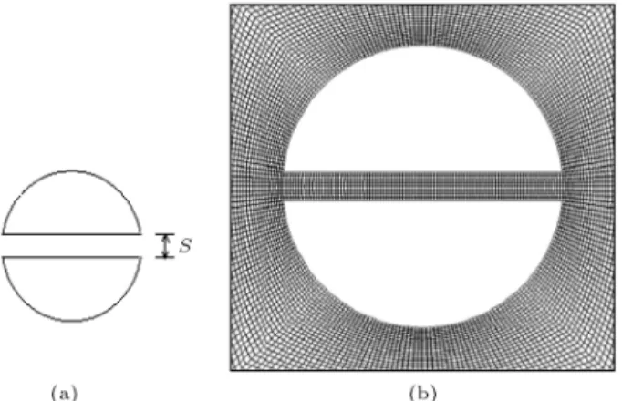
in the present work is 40 mm. The computational domain extends from 10D at the inlet to 20D at the outlet and extends from 10D to 10D in the cross-ow direction. The coordinate origin is located at the center of the cylinder, and the positive x-axis points downstream. The mesh near the cylinder wall should be dense enough to capture the behavior of the boundary layer, which plays an important role in predicting the forces acting on the cylinder surface. To facilitate meshing and speed up the simulation, the whole computational domain is divided into nine parts, as shown in Figure 1(a). A square with a side length of six times the cylinder diameter (zone 5) is created around the cylinder, and quadrilateral mesh is used. The dense structured mesh is employed in four zones adjacent to zone 5 (zones 2, 4, 6, and 8), and unstructured mesh is used in other four zones (zones 1, 3, 7 and 9). Mesh generation is initially completed in the square domain containing the cylinder (zone 5), and other zones will be meshed based on the initial grids. A typical 2D computational domain is displayed in Figure 1(b). A 60 60 quadrilateral mesh is chosen in zone 5, and the cylinder surface is divided into 240 cells, as shown in Figure 1(c). To testify the mesh resolution of computational domain, grid convergence test is carried out for ow past an unmodied circular cylinder at Re = 180. Mesh sensitivity analysis is performed by varying the mesh density in zone 5 and at the cylinder surface to assess its eect on the mean drag coecient, as discussed in Section 3.1. The ow conguration of a circular cylinder with a slit placed parallel to the ow direction along the cylinder diameter is sketched in Figure 2(a). Parameter s represents the width of the slit and varies from 0
Figure 1. (a) Sketch of the division of the computational domain. (b) Meshing of the computational domain. (c) Structured meshing around the cylinder (zone 5).
to 0:3D in the simulation. Computational domain near the cylinder wall is displayed in Figure 2(b). Quadrilateral meshes are also adopted in the slit and the cylinder surface.
In the Reynolds number range considered, the alternative vortex shedding will result in periodical uctuating forces on the cylinder wall. The forces
Figure 2. (a) Sketch of circular cylinder with a slit. (b) Structured meshing in the slit and around the cylinder.
acting on the circular cylinder are obtained as follows: FD=
2
Z
0
( p cos + wsin )Rd; (4)
FL= 2
Z
0
( p sin wcos )Rd: (5)
FD and FL are the total drag and lift forces,
respec-tively. R(= D=2) represents the radius of cylinder. The rst terms of both Eq. (4) and (5) are the components of the pressure, while the second terms are components of the shear stress. As for the cases of modied cylinders, the forces exerted on the two circular curve surfaces could be calculated by changing the domain of the integration and contribution of the pressure; shear force acting on the slit walls should also be considered. The drag and lift forces are nondimensionalized by U2D=2, thus the drag and lift coecients CD and CL
are described as follows: CD= UF2D
1D=2; (6)
CL= UF2L
1D=2: (7)
The non-dimensional shedding frequency, Strouhal number, is dened as:
St =fUsD
1; (8)
where it could be calculated by the Fast Fourier Transform (FFT) of the lift force component. Because the lift and drag forces are caused by the periodic upper and lower sheddings of the vortex, the lift and drag forces will be periodically oscillating in a fully developed ow past the circular cylinder and the time-averaged lift coecient becomes zero without control. It is remarkable that the amplitude of the drag and lift components is kept almost constant under the fully developed status.
2.3. Boundary conditions
The non-slip boundary condition is applied to the cylinder surface (and slit walls). Uniform free stream velocity is applied to the inlet of computational do-main: u = U1 and v = 0. @u=@x = 0 and @v=@x =
0 are applied at the exit of computational domain. Symmetry boundary conditions, @u=@y = 0 and v = 0, are applied at the upper and lower computational domain.
2.4. Numerical methods
The N-S equations are discretized using nite volume method, that is integral form of the conservation equations is solved in control volumes, which form a partition of the computational domain. Second order upwind scheme (discretizing the convective terms) and central dierence scheme (the diusive terms) are used. The second order implicit method is used for temporal discretization. The SIMPLE (Semi-Implicit Method for Pressure-Linked Equations) algorithm proposed by Patankar and Spalding (1972) [48] is applied to solve the pressure-velocity coupling. The Crank-Nicholson scheme is applied for the discretization of the time term. In the present work, convergence is veried if each residual of the above-mentioned equations is smaller than 10 6.
3. Validation
3.1. Grid convergence test
A non-uniform grid distribution with dense clustering of grid points in the regions having high gradients of parameters and coarser grids in the regions with low gradients of parameters are used. Grid convergence is performed to test the mesh dimensions chosen for the case under consideration. The test case of ow over an unmodied cylinder at Re = 200 is chosen to validate the spatial discretization. The grid sensitivity analysis is performed using four dierent grid sizes to be compared with the selected one. The grid discretization in the cylinder zone (zone 5) for all the test cases is N N = 30 30, 40 40, 50 50, 60 60, and 70 70, where 60 60 is the selected mesh resolution. The information of the test cases is given in Table 1, where L is the number of nodes along the cylinder surface. Taking the drag coecient of the selected mesh resolution, M4 (N N = 60 60), as a reference, deviation (absolute value) of the mean drag coecient in dierent test cases with respect to mesh sizes is displayed in Figure 3. It can be observed that as the mesh size reduces from M4 to M5, the drag force changes slightly at a convergence order of 10 4. Thus,
we chose M4 as the most appropriate mesh resolution for the model considered.
Richardson extrapolation [49] is applied to test the order of accuracy by using three grid resolutions
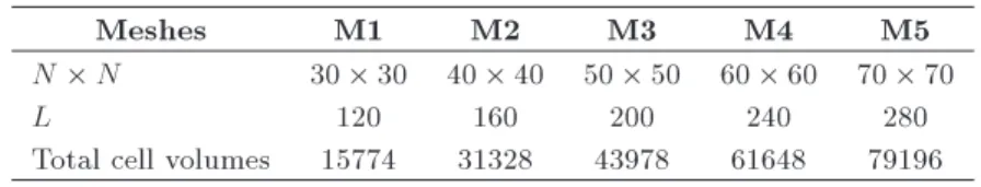
Table 1. Meshing features of the test cases.
Meshes M1 M2 M3 M4 M5
N N 30 30 40 40 50 50 60 60 70 70
L 120 160 200 240 280
Total cell volumes 15774 31328 43978 61648 79196
Figure 3. Drag deviation for dierent mesh sizes.
(M2, M3, and M4). Roache [50] generalized Richardson extrapolation by introducing the pth-order method:
fexact f1+ [(f1 f2)=(rp 1)]; (9)
where fexact is the exact solution and r is the grid
re-nement ratio. Considering the three mesh resolutions, the following is observed:
f2 f1= (fr3p f2) 32 1
(f2 f1)
rp21 1 ; (10)
in which f1, f2, and f3represent computed mean drag
force in case M4, M3, and M2, respectively, and r32=
40=50 = 0:8 and r21 = 50=60 = 0:8333. Finally, we
obtained result of p = 1:87, which is close to 2, and it is consistent with the second order accuracy of the discretization.
3.2. Validation of the code
Computational Fluid Dynamics software Fluent 6.3 is used in the present numerical simulation. There are no available results in literature to verify the present ones. Thus, it is necessary to conrm the accuracy of the present numerical simulation of ow past a circular cylinder; the results gained from an unmodied cylinder at Reynolds numbers from 60 to 200 are compared with available results to verify those of the present work. The numerical validations are mainly focused on the time-averaged drag coecient CM
D, amplitude of lift coecient, CLA, and shedding
frequency St.
The comparisons of parameters mentioned above with existing literature are shown in Tables 2-4. It can be observed that these characteristic values are in accordance with others' studies.
Table 2 shows the comparison of the computed mean drag coecient CM
D with available results, which
Table 2. Comparisons of mean drag coecient CM
D with literature at dierent Reynolds numbers.
Re 60 80 100 150 200
Present 1.426 1.375 1.348 1.330 1.342
He et al. (2000) [52] 1.39 1.35 1.35 1.36 Henderson (1995) [53] 1.42 1.37 1.35 1.33 1.34 Baranyi and Lewis (2006) [46] 1.41 1.36 1.34 1.33
Lu et al. [47] 1.41 1.37 1.35 1.33 1.34
Table 3. Comparisons of amplitude of lift coecient CA
L with literature at dierent Reynolds numbers.
Re 60 80 100 150 200
Present 0.150 0.260 0.350 0.530 0.700
Lu et al. (2011) [47] 0.14 0.25 0.34 0.53 0.69 Baranyi and Lewis (2006) [46] 0.13 0.24 0.32 0.51 Farrant et al. (2001) [54] 0.33 0.71 Linnick and Fasel (2005) [55] 0.34 0.70 Zhang et al. (2008) [56] 0.34 0.66 Le et al. (2008) [58] 0.26 0.68 Wang et al. (2009) [59] 0.26 0.71
Table 4. Comparisons of Strouhal number, St, with literature at dierent Reynolds numbers.
Re 60 80 100 150 200
Present 0.138 0.158 0.170 0.187 0.195 Lu et al. (2011) [47] 0.137 0.154 0.165 0.184 0.196 Wang et al. (2009) [59] 0.158 0.170 0.195 Williamson (1989) [60] 0.136 0.152 0.164 0.179 0.183 He et al. (2000) [52] 0.135 0.153 0.167 0.198
indicates good consistency. In general, the mean drag force is found to reduce as the Reynolds number augments. The cause is the decline of the viscous contribution which plays a role for the total drag force within the laminar ow regime [51]. The comparison of the amplitudes of uctuating lift coecient CA
L at
various Reynolds numbers is displayed in Table 3. Good agreements between the present work and other's numerical results are observed as well. Dierent from the drag force, the amplitude of lift uctuation is observed to increase rapidly as the Reynolds num-ber augments. Finally, the numerical validation of the Strouhal number is presented in Table 4. The good agreements between the computed results of the present work and the available numerical and exper-imental data also conrm that the present numerical model works well. It can be found that the Strouhal number augments gradually as the Reynolds number increases, suggesting that the period of vortex shedding from a blu body in the laminar ow regime may be prolonged at lower Reynolds number. To this point, it is necessary to realize that the lift force reects two important fundamental characteristics of ow past a blu body. One is the pressure distribution nearby the uid-solid interface and the other is the Strouhal number. The former correlates closely to the evolution of ow eld, while the latter depends on the vortex shedding frequency.
4. Results and analysis
The model is then applied to probe the ow over modied cylinders. The eects of the slit width ratios on the ow over a cylinder are investigated. For unsteady laminar ow over a cylinder, the alternative shedding vortex yields the uctuating forces, namely the drag force and lift force. Therefore, the drag and lift coecients are two signicant parameters which illustrate the variation of the ow eld. The shedding frequency of the vortex is determined by the lift uctuation, thus the Strouhal number, St, is calculated by the power spectrum of the lift coecient. The eects of the slit width ratios on the variation of the drag, lift coecients, and the shedding frequency at Re = 60, 80, 100, 150, 200, and 250 are investigated. The model of dierent slit width ratios used are s=D = 0, 0.10, 0.15,
0.20, 0.25, 0.30. Actually, the present conguration is derived from the cutting of the same cylinder. The dierence among the present cases is due to the slit caused by dierent cutting. To simplify the description, the cases are to be referred to as S0, S1, S2, S3, S4, and S5, henceforth.
4.1. Drag forces
In this section, the mean drag coecients are compared in the modied cases (with slit) with the corresponding value for unmodied case (without slit). Numerical simulations are carried out in the Reynolds number ranges from 60 to 250, and numerical results at Re = 150 and Re = 250 are specically discussed.
The mean drag coecients obtained numerically from the unmodied case (S0) are in good agreement with the values reported by other authors (Baranyi and Lewis [46], Lu et al. [47], He et al. [52], and Henderson [53], shown in Table 2). Figure 4 shows the variation of the drag coecients with Reynolds num-bers at dierent slit width ratios. A sharp reduction of the total drag coecients could be observed as the slit width ratio increases at Re = 150 250.
On the other hand, the decrease of the total drag forces is slight when the Reynolds number is relatively low. The maximum drag drop occurs in case S5 at Re = 250, with a drag reduction by 30.4%. The results presented demonstrate the eectiveness in improving the drag performance by slit modication.
Figure 4. Variation of the mean drag coecients with Reynolds numbers at dierent slit width ratios.
Table 5. Mean drag coecients of all the modied cases at Re = 60 250.
Re
s=D 60 80 100 150 200 250
0 1.426 1.375 1.348 1.330 1.342 1.350 0.10 1.423 1.372 1.334 1.310 1.274 1.249 0.15 1.419 1.363 1.322 1.269 1.219 1.166 0.20 1.379 1.344 1.316 1.198 1.119 1.064 0.25 1.377 1.308 1.242 1.111 1.015 0.970 0.30 1.362 1.277 1.197 1.067 0.980 0.939
Drag reduction performance of passive control method by placing a slit parallel to the ow direction was also found by Igarashi [31] and Olsen and Rajagopalan [32] in their experimental works. The decline of the total drag forces is caused by diminution of the pressure dierence between the higher pressure in the front stagnation zone and the lower pressure in the rear separated zone, which is derived from diverting part of the uid from the front stagnation point of the cylinder into the low pressure zone in the rear of the cylinder through an internal slit. The mean drag coecients of all the modied cases at Re = 60 250 are presented in Table 5.
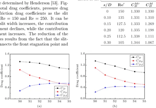
The drag force is a result of the convective motion of the cylinder through the uid. In viscous ow, the total drag force is contributed by the pressure and skin friction (or viscous) components. The pressure com-ponent causes a large drag contribution in total drag. The pressure and viscous contributions of the drag coecient from steady and unsteady two-dimensional computations were determined by Henderson [53]. Fig-ure 5 shows the total drag coecients, pressFig-ure drag coecients, and friction drag coecients as the slit width changes at Re = 150 and Re = 250. It can be found that as the slit width increases, the contribution of pressure component declines, while the contribution of viscous component increases. The reduction of the pressure drag forces results from the fact that the slit-formed channel connects the front stagnation point and
the rear low pressure zone of the cylinder, leading to the diminution of the pressure dierence between the front stagnation zone and the rear separated one of the cylinder. On the other hand, the increase of the skin friction forces is attributed to the two sides added by the slit. The compensation of the pressure drag force reduction for the viscous force increase results in the decrease of the total drag force.
For ow over usual circular cylinder and cylinder with slit, a uniform Reynolds number Re = U1D= is
dened. Next, we will discuss the Reynolds number, if it is recalculated because of the existence of slit in modied cylinders. For modied cylinders, the crosswise length as seen from the stream has been changed in consequence of the slit across the cylinder. A new Reynolds number, Re0 = U
1D0=, is dened,
in which D0 is the crosswise length as seen from the
stream considering slit width. Then, we will get ve new Reynolds numbers (Re0) for every Re (because
the Reynolds number is recalculated due to ve slit widths). A comparison study at Re = 150 is carried out to explore whether the modied cylinders (with slit) are still interesting when the Reynolds numbers are updated. Table 6 displays computed results, CM
D, for
Re = 150 in dierent cases and mean drag coecient, CM0
D , at corresponding Re0 for unmodied cylinders.
It could be observed that even though the Reynolds number is recalculated, the drag reduction feature of the modied cylinder is still satised. Another feature which deserves to be mentioned is that in the
Table 6. Drag reduction performance of modied slit model at Re0.
s=D Re0 CM0 D CDM
0 150 1.330 1.330 0.10 135 1.331 1.310 0.15 127.5 1.333 1.269 0.20 120 1.335 1.198 0.25 112.5 1.338 1.111 0.30 105 1.344 1.067
Figure 5. Total drag coecients, pressure coecients, and friction coecients at dierent control cases: (a) Re = 150; and (b) Re = 250.
considered Reynolds number range, the average drag coecient of ow over usual cylinder changes slightly (which could be referred to the work of Rajani et al. [51]). However, the percentage of drag reduction of the modied cylinder is signicant. To set a uniform criterion to evaluate the drag and lift forces as well as the vortex shedding structures for dierent control models, we still use the common Reynolds number denition for the following discussions.
4.2. Lift forces and shedding frequency
Vortex shedding from the upper and lower surfaces of the circular cylinder generates periodic pressure uctu-ations around the circular cylinder. The uctuating lift force is mainly due to the uctuating pressures acting on the surface of the cylinder [18]. When the shear layer is being shed downstream from one side of the surface, a low pressure region is evolved on that side, while a high pressure region is evolved on the opposite side. The phenomenon continues alternately, and hence, unsteady lift uctuations are experienced by the bodies at the frequency of the vortex shedding (fS) [57],
that is, the lift uctuation energy is concentrated on a band around fS. The Strouhal number St is a
non-dimensional transformation of the shedding frequency fS. The time traces of the uctuating lift coecient in
dierent cases are presented in Figure 6.
The amplitude of lift uctuation is greatly re-duced with the increase of the slit width at Re = 150, with a maximum reduction to an order of 10 4, as
shown in Figure 7. Similar results could be found at Re = 60, 80, and 100. However, a dierent feature of the CL variation is found at Re = 250. As the slit
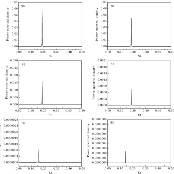
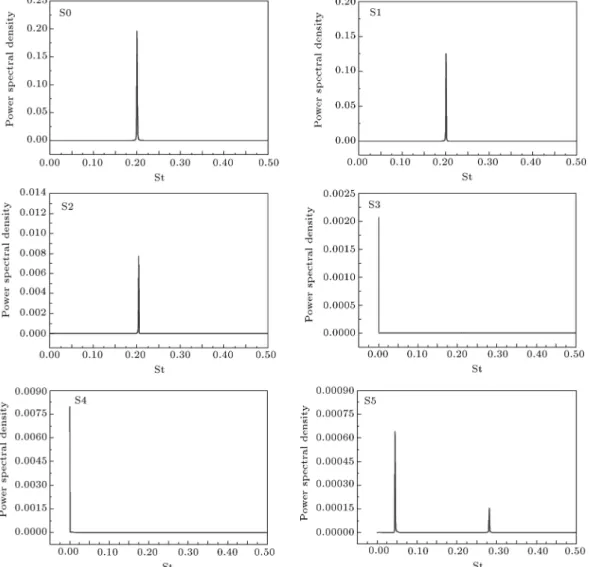
width ratio increases to 0.20 (S3), a positive value of the mean lift force could be found and the mean lift force is negative in the case S4. At the maximum slit width ratio of S=D = 0:30 (S5), a periodic oscillating lift force appears again, as shown in Figure 6. It is due to the onset of the vortex shedding from the slit. The phenomenon will be further discussed in the ow eld section by displaying the vortices contours. The shedding frequencies are determined by the lift coe-cient uctuation. The Strouhal number, St, is captured with the power spectral analysis of CL, as shown in
Figures 8 and 9. The obtained Strouhal numbers of Re = 150 and Re = 250 will be discussed separately. Figure 8 displays the FFT of the lift histories, the resulting Strouhal number, and corresponding power spectral density at Re = 150. A signicant drop of the power spectral density could be observed as the slit width ratio increases; however, the shedding frequency changes slightly from S0 to S3; while in cases S4 and S5, a favorable reduction of the St is observed, declining from 0.187 of case S0 to 0.162 in case S4 and 0.145 in case S5, respectively. When Re is equal to 250, a St = 0 is found in cases S3 and S4 due to the disappearance of the lift uctuation, while in case S5, a secondary frequency is observed, which is the result of the existence of the vortices shedding from the slit (as shown in Figure 9).
Figure 6. Time histories of the lift coecient in dierent modied cases at Re = 150 and Re = 250.
Figure 8. Strouhal number and power spectral density at Re = 150.
4.3. Flow eld
The unsteady ow over a circular cylinder is initi-ated by the separiniti-ated boundary layers that naturally become unstable beyond the rst critical Reynolds number. The separation point is located at the surface of the cylinder, where the shear stress is zero. As the separation angle varies during the period of vortex shedding, the separation position is derived from the ow eld. The shear stress at the cylinder surface is obtained from the tangential velocity gradient along the radius of the cylinder, namely @u=@n. At the
location ahead of a special position of the cylinder wall, the distribution of boundary layer velocity, @u=@n,
is positive. The positive pressure gradient in the circumferential direction (adverse pressure) will result in the decrease of @u=@n. If the adverse pressure
gradient persists, @u=@n will be zero at a position,
and the ow will be separated from the boundary. For the unmodied cylinder, the separated shear layers are deected inwards immediately after passing the
sepa-ration point, and a back ow occurs in the downstream separation, forming the well-known Karman vortex. The numerical results show that the slit through the cylinder has altered the evolution of vortex formation signicantly in the cylinder wake. In the cylinder-slit conguration, the free shear layers roll up further downstream progressively from the cylinder as the size of the slit increases. The phenomenon mentioned above could be explained by the following facts that with the expansion of the slit width, the uid quantity owing through the slit increases, and vortex shedding from the slit could hinder the interaction between the top and bottom vortices forming the cylinder surface, thus rolling up occurs where the shear layers have had more opportunity to diuse, resulting in less compact vortex cores. Such shed vortices are less ecient in generating large pressure variations between the upper and lower sides of the cylinder, causing the observed decrease in drag and lift forces.
Figure 9. Strouhal number and power spectral density at Re = 250.
Figure 11. Instantaneous vorticity contour of ow past modied and unmodied cylinders at Re = 250.
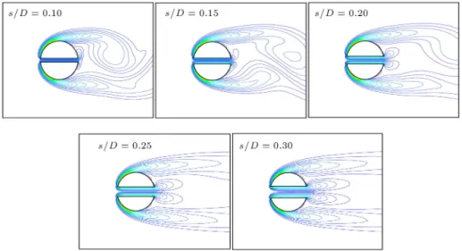
Figure 12. Close-up view of the vorticity contour of ow past modied cylinders at Re = 150.
contours of the entire ow eld for all cases at Re = 150 and Re = 250. Detailed displays of the vortex shedding near the slit corresponding to Figures 10 and 11 are presented in Figures 12 and 13. It is obvious that the wake ow behind the cylinder is strongly aected by the slit. The most interesting feature is the appearance of the vortices generated from the slit with the expansion of the slit width, which impedes the interaction between the upper and lower shedding shear layers. Thus, the uid through the slit drives the vortex formation region downstream and changes the anti-symmetric feature of the vor-tex shedding from the cylinder wall. Therefore, a suppression of the vortex shedding could be obtained by the modied slit method. Detailed analysis of
the wake ow eld will be presented in the following paragraphs.
First, the ow eld of cylinder-slit ow at Re = 150 is displayed, as shown in Figure 10. For small slit ratio up to s=D = 0:10 (S1), the vortex shedding feature is slightly dierent from that of a cylinder without a slit (S0). As the slit width becomes larger, the rolling up of the separated shear layers is extended backwardly. As a consequence, the vortex formation region is pushed downstream due to the appearance of the slit vortices, which could be observed clearly in Figure 12. The vortices caused by the slit hinder the interaction between the upper and lower shear layers separated from the cylinder and delay the furling of the separated shear layers. In
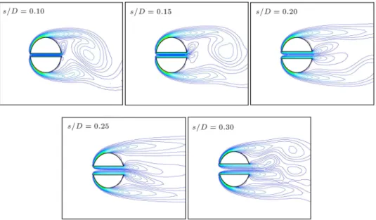
Figure 13. Close-up view of the vorticity contour of ow past modied cylinders at Re = 250.
case S5, the vortex's formation region behind the cylinder is driven downstream farthest when the lift force is minimum (at an order of 10 4), as shown in
Figure 7.
Next, we pay particular attention to the modied cases at Re = 250, as shown in Figure 11. For small slit ratios up to s=D = 0:10, the same phenomenon is observed as that at Re = 150. Cases S2, S3, and S4, however, show more dierent vortex structures. Partial enlarged drawings of the vorticity contour near the slit are displayed in Figure 13. As a result of the formation of stronger slit vortices, the slit vortices are biased towards either upper side or lower side, sporadically, resulting in mean value of the lift coecient of 0.045 (S3) and -0.095 (S4), as shown in Figure 6. The ow pattern is similar to the biased bi-stable ow happened in ow past side-by-side cylinders when the distance between two cylinders is small [33]. However, for modied cases at Re = 150, the slit vortices only help to elongate the shear layer and will not interact with cylinder vortex. In the case S5, noticeable oscillating of the vortex shedding from the cylinder surface occurs again (CL = 0:06 +0:06). The cause is that
vortices formed by the slit shed interact with the shear layers separated from the cylinder surface. The small scale secondary vortex generated at the rear edge of the slit (case S5, shown in Figure 13), which provides additional perturbations to the separated shear layers, results in the re-emergence of the uctuating lift forces (as shown in Figure 6). Another corresponding result is the appearance of a secondary shedding frequency as shown in Figure 9.
In order to get a deeper insight on how the slit width will inuence the ow structure if the slit width continually increases, we add three new modied cases, that is, s=D = 0:35, 0.40, and 0.45. The instantaneous
vorticity contour of the new cases is displayed in Figure 14.
It can be observed that for the case of Re = 150, ow structures with larger slit width are similar to those of s=D = 0:30, proving that the structure shown in Figure 14(a) is the most stable state at this Reynolds number. Modied cases of s=D = 0:35 and s=D = 0:40 show similar vortex structures with those of s=D = 0:30 under the condition that Re = 250. Secondary vortices shedding from the rear edge of slit would interact with the vortices shedding from the cylinder surface. However, for the case of s=D = 0:45, both the main vortex shedding from the surface of the cylinder and the secondary one from the rear edge of slit disappear; the wake ow structure tends to be more stable. Therefore, we can come to the conclusion that in the laminar regime, the slit width of the optimal modied cylinder increases with the augmentation of Reynolds number. 5. Conclusions
A passive ow control method is proposed in the present work to reduce the uctuating forces acting on the cylinder surface and suppress vortex shedding in the low Re number laminar region. The eect of the width of the slit placed along the cylinder diameter parallel to the incoming ow is numerically studied. Simulations are performed at a Reynolds number range of 60 to 250. The time traces of drag and lift coecients, the Strouhal numbers, and ow features are comprehensively presented and compared with dierent modied cases in order to reveal the impact of slit width ratios on the behavior of the circular cylinder wake ow. It is shown that the nature of the vortex shedding evolution is signicantly altered by the slit through the cylinder. In the
Figure 14. Instantaneous vorticity contour of ow past cylinders with larger slit.
comparison of the modied cylinders with conventional one, particular attention is paid to numerical results obtained at Re = 150 and Re = 250. The reduction of the drag force is caused by the inner duct formed by the slit which directs part of the uid in the front stagnation region to the rear stagnation region and consequently decreases the pressure dierence between the front stagnation and rear separated region. The lift coecient also declines as the slit width increases at Re = 60 200. The slit placed parallel to the ow direction also prolongs the formation of wake vortex. A very interesting vortex pattern found in the modied case is the vortex shedding of the slit and its interaction with the cylinder vortices, which contributes to the delay of the boundary layer separation. In conclusion, the modied slit method, which does not require an ad-ditional expenditure of energy, is a promising technique for drag reduction and vortex shedding suppression. Acknowledgement
The authors gratefully acknowledge the nancial sup-port by the National Nature Science Fund of China (No. 50476063).
Nomenclature
D The diameter of the cylinder; FD Drag forces;
CD Drag coecients;
CM
D Time-averaged drag coecient;
St Strouhal number; p Pressure;
fs Shedding frequency of the vortex;
U1 The free-stream velocity;
FL Lift forces;
CL Lift coecients;
CA
L Amplitude of lift coecient;
Re Reynolds number; u; v; x; y Velocity components; x; y Coordinate direction. Greek symbol
Kinematic viscosity of uid;
Angle between the front stagnation streamline and a vector normal to the cylinder surface;
Density of uid; w Shear stress;
Time.
References
1. Williamson, C.H.K. \Vortex dynamics in the cylinder wake", Annu. Rev. Fluid Mech., 28, pp. 477-539 (1996).
2. Behara, S. and Sanjay, M. \Wake transition in ow past a circular cylinder", Physics Fluids, 22(11), pp. 114104.1-114104.11 (2010).
3. Qu, L., Norberg, Ch., Davidson, L., Peng, SH. et al. \Quantitative numerical analysis of ow past a circular cylinder at Reynolds number between 50 and 200", Journal of Fluids and Structures, 39, pp. 347-370 (2013).
4. Williamson, C.H.K. and Govardhan, R. \Vortex-induced vibration", Annu. Rev. Fluid Mech., 36, pp. 413-455 (2004).
5. Roshko, A. \Perspectives on blu body aerodynam-ics", J. Wind Eng. Industr. Aerodyn., 49(1-3), pp. 79-100 (1993).
6. Choi, H., Jeon, W.P. and Kim, J. \Control of ow over a blu body", Annu. Rev. Fluid Mech., 40(1), pp. 113-139 (2008).
7. Wang, J.S., Xu, Y.X. and Tian, Y.S. \Active control of circular cylinder ow by aliated rotating cylinders", Sci. China Tech. Sci., 56(5), pp. 1186-1197 (2013). 8. Muralidharan, K., Muddada, S. and Patnaik, B.S.V.
\Numerical simulation of vortex induced vibrations and its control by suction and blowing", Applied Mathematical Modeling, 37(1-2), pp. 284-307 (2013). 9. Chen, W.L., Xin, D.B., Xu, F. et al. \Suppression of
vortex-induced vibration of a circular cylinder using suction-based ow control", Journal of Fluids and Structures, 42(4), pp. 25-39 (2013).
10. Bao, Y. and Tao, J. \Active control of a cylinder wake ow by using a streamwise oscillating foil", Phys. Fluids, 25(5), pp. 416-423 (2013).
11. Subhash Reddy, M., Muddada, S. and Patnaik, B.S.V. \Flow past a circular cylinder with momentum in-jection: optimal control cylinder design", Fluid Dyn. Res., 45(1), pp. 15501-15527 (2013).
12. Tang, S. and Aubry, N. \On the symmetry breaking instability leading to vortex shedding", Phys. Fluids, 9, pp. 2550-2561 (1997).
13. Wehrmann, O.H. \Reduction of velocity uctuations in a Karman vortex street by a vibrating cylinder", Phys. Fluids, 8(4), pp. 760-761 (1965).
14. You, D., Choi, H., Choi, M.R. et al. \Control of ow induced noise behind a circular cylinder using splitter plates", AIAA J., 36(11), pp. 1961-1967 (1998). 15. Karniadakis, G.E. and Triantafyllou, G.S. \Frequency
selection and asymptotic states in laminar wakes", J. Fluid Mech., 199, pp. 441-469 (1989).
16. Poncet, P. and Koumoutskakos, P. \Optimization of vortex shedding in 3D wakes using belt actuators", Int. J. Oshore Polar Eng., 15(1), pp. 7-13 (2005). 17. Poncet, P., Hildebrand, R., Cottet, G.-H., et al.
\Spa-tially distributed control for optimal drag reduction of
the ow past a circular cylinder", J. Fluid Mech., 599, pp. 111-120 (2008).
18. Gozmen, B., Akilli, H. and Sahin, B. \Passive control of circular cylinder wake in shallow ow", Measure-ment, 46(3), pp. 1125-1136 (2013).
19. Lu, L., Liu, M.M., Bin, T., et al. \Numerical investi-gation of uid ow past circular cylinder with multiple control rods at low Reynolds number", Journal of Fluids and Structures, 48, pp. 235-259 (2014). 20. Oruc, V. \Passive control of ow structures around a
circular cylinder by using screen", Journal of Fluids and Structures, 33(5), pp. 229-242 (2012).
21. Bao, Y. and Tao, J. \The passive control of wake ow behind a circular cylinder by parallel dual plates", Journal of Fluids and Structures, 37, pp. 201-219 (2013).
22. Rao, A., Thompson, M.C., Leweke, T., et al. \The ow past a circular cylinder translating at dierent heights above a wall", Journal of Fluids and Structures, 41, pp. 9-21 (2013).
23. Schumm, M., Berger, E. and Monkewitz, P.A. \Self-excited oscillations in the wake of two-dimensional blu bodies and their control", J. Fluid Mech., 271, pp. 17-53 (1994).
24. Strykowski, P.J. and Hannemann, H. \Temporal sim-ulation of the wake behind a circular cylinder in the neighborhood of the critical Reynolds number", Acta Mech., 90(1), pp. 1-20 (1991).
25. Bearman, P. and Owen, J. \Reduction of blu-body drag and suppression of vortex shedding by the intro-duction of wavy separation lines", J. Fluids Struct., 12(1), pp. 123-130 (1998).
26. Darekar, R.M. and Sherwin, S.J. \Flow past a square-section cylinder with a wavy stagnation face", J. Fluid Mech., 426, pp. 263-295 (2001).
27. Dobre, A., Hangan, H. and Vickery, B.J. \Wake control based on spanwise sinusoidal perturbations", AIAA J., 44(3), pp. 485-492 (2006).
28. Lee, S.J., Lim, H.C., Han, M. et al. \Flow control of circular cylinder with a V-grooved micro-riblet lm", Fluid Dyn. Res., 37(4), pp. 246-266 (2005).
29. Yang, J.T., Yen, C.W. and Tsai, G.L. \Flame stabiliza-tion in the wake ow behind a slit V-gutter", Combust. Flame, 99(2), pp. 288-294 (1994).
30. Tsuchiya, K. \The clouds with the shape of Karman vortex streets in the wake of Cheju Island", Korea. J. Meteor. SOC. Japan, 47, pp. 457-465 (1969).
31. Igarashi, T. \Flow characteristics and a circular cylin-der with a slit. 1st report, ow control and ow patterns", Bulletin of JSME, 21(154), pp. 656-664 (1978).
behind modied circular cylinders", J. Wind. Eng. Ind. Aerodyn., 86(1), pp. 55-63 (2000).
33. Zdravkovich, M.M. \Review of ow interference be-tween two circular cylinders in various arrangements", ASME Journal of Fluids Engineering, 99(4), pp. 618-633 (1977).
34. Zdravkovich, M.M. \The eects of interference be-tween circular cylinders in cross ow", Journal of Fluids and Structures, 1(2), pp. 239-261 (1987). 35. Bearman, P.W. and Wadcock, A.J. \The interaction
between a pair of circular cylinders normal to a stream", Journal of Fluid Mechanics, 61(3), pp. 499-511 (1973).
36. Kiya, M., Arie, M. and Tamura, H. \Vortex shed-ding from two circular cylinders in staggered arrange-ments", ASME Journal of Fluids Engineering, 102(2), pp. 166-173 (1980).
37. Zdravkovich, M.M. \Flow induced oscillations of two interfering circular cylinders", Journal of Sound and Vibration, 101(4), pp. 511-521 (1985).
38. Williamson, C.H.K. \Evolution of a single wake behind a pair of blu bodies", J. Fluid Mech., 159, pp. 1-18 (1985).
39. Kim, H.J. and Durbin, P.A. \Investigation of the ow between a pair of circular cylinders in the opping regime", Journal of Fluid Mechanics, 196, pp. 431-448 (1988).
40. Wood, C. \The eect of base bleed on a periodic wake", J. Roy. Aero. Soc., 68, pp. 477-482 (1964).
41. Lin, J., Towghi, J. and Rockwel, D. \Near-wake of a circular cylinder: control by steady and unsteady surface injection", J. Fluids Struct., 9(6), pp. 659-669 (1995).
42. Kim, J. and Choi, H. \Distributed forcing of ow over a circular cylinder", Phys. Fluids, 17(3), pp. 033103.1-033103.16 (2005).
43. Baek, H. and Karniadakis, G.E. \Suppressing vortex-induced vibrations via passive means", J. Fluids Struct., 25(5), pp. 848-866 (2009).
44. Norberg, C. \Flow around a circular cylinder: aspects of uctuating lift", J. Fluids Struct., 15(3-4), pp. 459-469 (2001).
45. Williamson, C.H.K. and Roshko, A. \Vortex formation in the wake of an oscillating cylinder", J. Fluids Struct., 2(4), pp. 355-381 (1998).
46. Baranyi, L. and Lewis, R.I. \Comparison of a grid-based CFD method and vortex dynamics predictions of low Reynolds number cylinder ows", Aeronaut. J., 110(1103), pp. 63-71 (2006).
47. Lu, L., Qin, J.M., Teng, B., et al. \Numerical investigations of lift suppression by feedback rotary
oscillation of circular cylinder at low Reynolds num-ber", Phys. Fluids, 23(3), pp. 033601.1-033601.15 (2011).
48. Patankar, S.V. and Spalding, D.B. \A calculation procedure for heat, mass and momentum transfer in three-dimensional parabolic ows", Int. J. Heat Mass Transfer, 15(10), pp. 1787-1806 (1972).
49. Richardson, L.F. and Gaunt, J.A. \The deferred approach to the limit. Part I. Single lattice, Part II. Interpenetrating lattices", Phil. Trans. R. Soc. Lond., A1, 226(636-646), pp. 299-361 (1927).
50. Roache, P.J. \Perspective: A method for uniform reporting of grid renement studies", J. Fluids. Eng., 116(3), pp. 405-413 (1994).
51. Rajani, B.N., Kandasamy, A. and Majumdar, S. \Nu-merical simulation of laminar ow past a circular cylin-der", Appl. Math. Model., 33(3), pp. 1228-1247 (2009). 52. He, J.W., Glowinski, R., Metcalfe., R. et al. \Active control and drag optimization for ow past a circular cylinder I. Oscillatory cylinder rotation", J. Comput. Phys., 163(1), pp. 83-117 (2000).
53. Henderson, R.D. \Details of the drag curve near the onset of vortex shedding", Phys. Fluids, 7(9), pp. 2102-2104 (1995).
54. Farrant, T., Tan, M. and Price, W.G. \A cell boundary element method applied to laminar vortex shedding from circular cylinders", Comput. Fluids, 30(2), pp. 211-236 (2001).
55. Linnick, M.N. and Fasel, H.F. \A high-order immersed interface method for simulating unsteady incompressible ows on irregular domains", J. Comput. Phys., 204(1), pp. 157-192 (2005).
56. Zhang, X., Ni, S.Z. and He, G.W. \A pressure-correction method and its applications on an unstructured Chimera grid", Comput. Fluids, 37(8), pp. 993-1010 (2008).
57. Gerrard, J.H. \An experimental investigation of the oscillating lift and drag of a circular cylinder shedding turbulent vortices", J. Fluid Mech., 11(2), pp. 244-256 (1961).
58. Le, D.V., Khoo, B.C. and Lim, K.M. \An implicit-forcing immersed boundary method for simulating viscous ow in irregular domains", Comput. Meth-ods Appl. Mech. Eng., 197(25-28), pp. 2119-2130 (2008).
59. Wang, Z.L., Fan, J.R. and Cen, K.F. \Immersed boundary method for the simulation of 2D viscous ow based on vorticity-velocity formulations", J. Comput. Phys., 228(5), pp. 1504-1520 (2009). 60. Williamson, C.H.K. \Oblique and parallel modes of
vortex shedding in the wake of a circular cylinder at low Reynolds number", J. Fluid Mech., 206, pp. 579-627 (1989).
Biographies
Wang Jian Sheng, PhD, is a Professor in the Department of Thermal Energy Engineering at School of Mechanical Engineering, Tianjin University, Tianjin, P. R. China. He received a BS degree in Power Machine and MS degree in Thermal Energy Engineering from Tianjin University, Tianjin, P. R. China, in 1984 and 1992, respectively, and a PhD degree in Fluid Mechan-ics from Tianjin University, Tianjin, P. R. China in
1995. His research interests include Computational Fluid Dynamics, Numerical Heat Transfer, Heat Trans-fer Enhancement, Flow Control, and Drag Reduction. Wang Chen is a postgraduate in the Department of Mechanical & Mechatronics, University of Waterloo, Waterloo, Canada. He received his BS degree in En-gineering Mechanics from Tianjin University, Tianjin, P. R. China, in 2015. His research interests include computational uid mechanics and heat transfer.