Sharif University of Technology
Scientia IranicaTransactions B: Mechanical Engineering www.scientiairanica.com
Numerical assessment of turbulence eects on forces,
spray parameters, and secondary impact in wedge
water entry problem using k
" method
R. Shademani and P. Ghadimi
Department of Marine Technology, Amirkabir University of Technology, Tehran, P.O. Box 15875-4413, Iran. Received 12 May 2015; received in revised form 12 February 2016; accepted 10 May 2016
KEYWORDS Wedge water entry; Free surface; Impact force; Secondary impact; Finite volume method; Volume of uid.
Abstract. The present paper focuses on the assessment of turbulence eects on the impact force, spray, and secondary impact force of the wedge water entry. For this purpose, a nite element-based nite volume method code coupled with volume of uid has been developed. The k " method has also been implemented to model the turbulence eects. The developed code is validated against experimental data with good accordance and is then used to model the water entry of wedges with deadrise angles ranging from 10 to 60 degrees at dierent velocities of 1 and 2 m/s with laminar and turbulent assumptions. Subsequently, the resulting forces and free surfaces are compared for three critical instances of \peak", \hollow", and \2nd impact". It is illustrated that turbulence has negligible eects on the force and free surface in the main water entry process. However, turbulent eects rise up to 14.23% for the secondary impact forces.
© 2017 Sharif University of Technology. All rights reserved.
1. Introduction
The water entry problem has been numerically and analytically investigated by many researchers using various methodologies through applying dierent as-sumptions on the physics of the ow. However, there are still uncertainties about some of these assumptions and their eects on the results. Accordingly, there are choices to be made prior to the solution of the problem, which are still unclear.
One of these assumptions is the choice between turbulent and laminar ows. Turbulence can be described as the chaotic behavior of the uid. Although there is not a clear denition of \turbulence", the common aim of dierent turbulence theories is to describe these random behaviors as formulated uc-tuations in the uid properties. These models are
*. Corresponding author. Tel.: +98 21 64543110; Fax: +98 21 66412495
E-mail address: [email protected] (P. Ghadimi)
mainly extracted either by imposing dierent assump-tions on the uid or by the use of relaassump-tions deduced from the experiments. Therefore, using turbulence models does not necessarily guarantee better results in many situations. Indeed, one of the ambiguities concerning the ow around wedges in the water entry problem is whether it should be assumed laminar or turbulent.
Before addressing this question, which is the main concern of the present manuscript, a literature review of dierent works on the simulation of water entry problem in recent years is presented to highlight the importance of this problem in the scientic commu-nity.
Water entry of wedges has been simulated using many dierent numerical methods. Luo et al. [1] used Finite Element Method (FEM) to solve this problem with a laminar assumption. Yang and Qiu [2] also assumed a laminar ow and used Finite dierence method to solve the water entry problem. The newly introduced Smoothed Particle Hydrodynamics method
224 R. Shademani and P. Ghadimi/Scientia Iranica, Transactions B: Mechanical Engineering 24 (2017) 223{236
(SPH) has also been used in the recent years [3-6] to study this problem. However, it has mainly been used in conjunction with a turbulence theory. Moreover, Wang and Wei [7], Yin and Qian [8], and Sun et al. [9] used Boundary Element method to solve the water entry problem by using potential theory, which basically neglects the viscosity eects and hence the turbulence eects. On the other hand, analytical method has been used by Ghadimi et al. [10] by applying the Schwartz-Christoel conformal mapping, a solution which neglects viscosity eects. The works by Gao et al. [11] and Wu et al. [12] are other studies, which have used potential theory to solve the wedge water entry problem. Other researchers who chose laminar assumptions include Khabakhpasheva and Korobkin [13], Yamada et al. [14], Alaoui and Neme [15], and Luo et al. [16]. On the other hand, other researchers who have conducted a turbulent simulation include Yang et al [17-19], Feizi Chekab et al. [20], Ghadimi et al. [21,22], Farsi and Ghadimi [23-25], and Viviani et al. [6].
As extracted from the literature, the best choice between laminar and turbulent simulations is not so clear. Accordingly, the focus of the present paper is to show the dierences of the eects of laminar and turbulent assumptions in the water entry problem. To this end, Navier-Stokes equations are solved using nite element-based nite volume method (FEM-FVM) cou-pled with volume of uid (VOF) method. To consider the turbulence eect, the k " turbulence model has been implemented in the code. Wedges with deadrises of 10 to 80 degrees have been considered to assess the turbulence eect at extremely low and extremely high deadrise angles. Width of the considered wedges has been assumed constant as a design parameter. Specic parameters are dened for describing and analyzing the spray and cavity formation above the chine for comparison purposes.
In the following sections, after describing the gov-erning equations and discretization methods, validation of the code is presented. Afterward, the comparison of forces, spray parameters, and cavity formation is presented for laminar and turbulent simulations of dierent wedges.
2. Governing equations 2.1. Momentum equations
Navier Stokes equations are solved for a two-phase ow in a homogeneous mode using nite element-based nite volume method coupled with volume of uid method. The continuity and conservation of momentum equations can be written as:
@ @t +
@u @x +
@v
@y = 0; (1)
@' @t + @u' @x + @v' @y = @ @x @' @x+ @ @y @'
@y+S; (2) where, x and y are the coordinate directions, t is time, is the uid density, is the dynamic viscosity, S =
@P
@x + gxand ' = u are in the x direction, and S = @P
@y + gy and ' = v are in the y direction, in which
P is the pressure and u and v are the velocities in the x and y directions, respectively.
2.2. Volume Of Fluid (VOF) method
In the volume of uid scheme, a scalar parameter named volume fraction () is dened as the fraction of an element lled with one uid. As a result, (1 ) is the fraction of the second uid. VOF method is based on the conservation of the scalar parameter () with respect to time and space, which can be described by the relation:
@
@t + r:(U) = 0; (3) where U is the uid velocity vector. By using the volume fraction, an equivalent density and viscosity can be calculated for each element using the equations:
eq= 1+ (1 )2;
eq= 1+ (1 )2; (4)
where is the volume fraction and 1, 2 and 1, 2
are the density and viscosity of the uids, while eq
and eq are the equivalent uid density and viscosity,
respectively.
In the VOF scheme, Eq. (3) is used to move the volume fraction eld with the uid velocities. In this way, the free surface is transferred using the velocity eld of both uids.
In the next section, the applied numerical method is briey explained.
2.3. Turbulence model
To implement the turbulence eect, the standard k " turbulence model has been used, which is found in most CFD references. The transport equations for k and " are as follows:
@(k) @t +
@
@xj(Ujk) =
@ @xj
+ t
k
@k @xj
+ Pk " + Pkb; (5)
@(") @t +
@
@xj(Uj") =
@ @xj
+t
"
@" @xj
+k"(C"1Pk C"2" + C"1P"b); (6)
where t is the turbulent viscosity; Pk is the product
of k; Pkb and P"b are the buoyancy eects; and C"1,
2.4. Numerical method
In the nite element-based nite volume method (FEM-FVM), shape functions are dened on each node of the elements as:
' =
NodeX i=1
Ni'i;
where Ni is the shape function at node i and 'i is the
quantity of ' at that node. The discretization method adopted in this paper is based on the fully coupled Rhie and Chow [26] algorithm, applied on a collocated triangular grid system for a 2D uid ow. The shape functions for triangular elements are as follows:
N1=
y2 y1
DET
x+
x3 x2
DET
y+
x2y3 x3y2
DET
;
N2=
y3 y1
DET
x+
x1 x3
DET
y+
x3y1 x1y3
DET
;
N3=
y1 y2
DET
x+
x2 x1
DET
y+
x1y2 x2y1
DET
;
DET = (x1y2+x2y3+x3y1 y1x2 y2x3 y3x1); (7)
where DET is the determinant of the coordinates matrix and xiand yiare the coordinates of the triangle
points. By implementing the Navier-Stokes equations in a control volume, the following equation can be obtained:
@'
@t
i~8i
| {z }
Transient
+ u'ds| xjj;k{z+ v'dsyjj;k} Convection
= r':!!ds
j;k
| {z }
Diusion
+ Z
~8i
bd8 | {z }
Source
: (8)
The transient terms can be expressed on a control volume (~8i) as follows:
@ @t
Z
8'd8 =
@'@ti
~8i= ~8i'i ' 0 i
t : (9) The Upwind Dierence Scheme (UDS) is used for the
convection term on a control line j, k as follows: Z
Sj;k
~V 'ds = (~V :!ds)j;k'j;k: (10)
The false diusion problem is eliminated by using the method introduced by Karimian and Schneider [27] as in:
~V :!ds
j;k'j;k=
!V :^ !ds
j;k'j;k; (11)
where 'j is calculated as:
'j= 'upj+@'@ss: (12)
For the x direction, Eq. (13) is obtained:
^uj=(v)s j jdUupj+
dd2 j 3 X i=1
(Ni)jUi
1 d @ @x 3 X i=1
(Ni)jPj: (13)
Here, j is the present node and i is the element node. Also, pressure and diusion terms are modeled as follows:
Z
8
@p @xd8 =
Z
S P dsx;
Z
8
@p @yd8 =
Z
S P dsy; (14)
r':!!ds
j;k=
@'
@xdsx+ @' @ydsy
j;k: (15)
The developed code is based on the global algorithm displayed in Figure 1.
By using the algorithm displayed in Figure 1, a computer code has been developed for solving the wedge water entry problem. In the next sections, after validating the code, the laminar and turbulent water entry problems of dierent wedges are analyzed and compared.
226 R. Shademani and P. Ghadimi/Scientia Iranica, Transactions B: Mechanical Engineering 24 (2017) 223{236
Figure 2. Water entry forces (left) and free surface (right): Comparison of laminar and turbulent numerical results versus experimental data [28] for (a) 10 degrees and (b) 15 degrees of deadrise angle.
2.5. Wedge force calculation
One of the most important outputs of the present study is the force acting on the wedge while entering the water. The force acting on the wedge is due to pressure and shear stress, which are calculated by the following equations:
Fn = Fpressure=
Z
Wedge.surface
P dA; (16)
Ft= Fshear.stress=
Z
Wedge.surface
dA; (17)
where Fn is the force normal to the wedge, Ft is the
force tangential to the wedge, and is the shear stress. The vertical impact force (F ) is calculated using the relation:
F = Fncos + Ftsin ; (18)
where is the angle of the wedge surface with the horizon.
3. Validation
To validate the developed code, experimental results of Tveitnes et al. [28] have been utilized. Water entries of two wedges with 10 and 15 degrees of deadrise angle have been simulated at an entry speed of 0.94 m/s and the results are illustrated in Figure 2.
As observed in Figure 2, there are reasonable errors of 5.36% and 7.48% for the wedges of 10 degrees and 15 degrees, respectively. Also, by comparing the numerically obtained free surface against the plots provided by Tveitnes et al. [28], it is demonstrated that there is good similarity between the numerical and experimental free surfaces.
The local Reynolds number of the ow near the wedge reaches 5:5 106, which is in the range of
turbulence. However, the question is how much the tur-bulence assumptions may aect the ow analysis for the wedge water entry and under what circumstances the turbulence eects could be neglected. As a preliminary comparison between laminar and turbulent results, it is
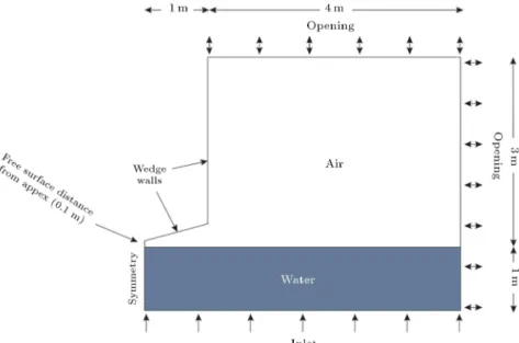
Figure 3. Numerical domain and boundary conditions illustrated in a sample mesh of the problem.
clear that there is no dierence in the force estimation. However, there are slight dierences in the free surfaces. To better diagnose the eect of turbulence in the water entry problem, more tests at dierent deadrise angles are conducted in the next section.
4. Results and discussion
As pointed out earlier, the present study is focused on the eects of turbulent and laminar assumptions on the impact force, the secondary impact force, and the free surface of the water entry problem. To this end, the problem should be solved for a wide range of deadrises with laminar and turbulent assumptions. In this section, the ow characteristics for wedges with 10, 15, 20, 30, 40, 50, and 60 degrees of deadrise angles are presented. The numerical setup shown in a sample mesh of the problem is illustrated in Figure 3.
As observed in Figure 3, because of the symmetric nature of the problem, half of the wedge has been modeled and a symmetry boundary condition has been applied. The wedge is modeled as a no-slip wall. An initial distance of 0.1 m has been taken into account to better capture the impact. The water is injected to the domain from the bottom to raise the water surface level and simulate downward motion of the wedge. Also, a hexagonal mesh has been applied and it is tried to obtain the highest possible orthogonal-ity.
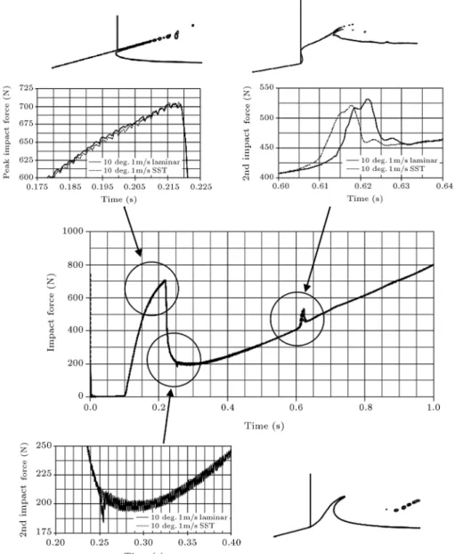
The typical impact force versus time is presented in Figure 4.
As shown in Figure 4, there are 3 critical points in the water entry impact force versus time, which are hereafter named \peak", \hollow", and \2nd Impact". At each point, the force and free surface for all deadrise angles at two entry velocities are extracted
Figure 4. Denition of the critical moments for comparison of force and free surface.
and overlaid for comparing the laminar and turbulent solutions. Typically extracted gures are presented in Figure 5 for one particular deadrise angle and velo-city.
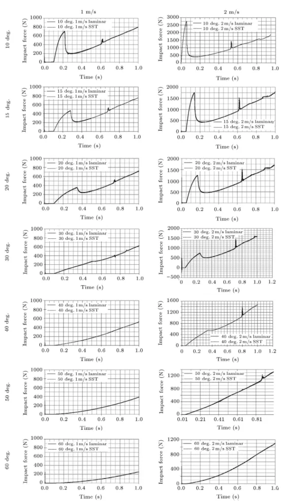
The obtained impact forces versus time for dif-ferent deadrise angles are presented in Figuew 6. As observed in Figure 6, there is hardly any dierence between laminar and turbulent simulations and the turbulence eects may be neglected.
In the following subsections, the forces and free surfaces in these three critical times are presented and the dierence between laminar and turbulent solutions is examined.
4.1. Turbulent versus laminar at \peak" point When plotting the trend of impact force over time, it is observed that the impact force grows while the spray root ascends along the wedge. When the spray root arrives at the chine, the impact force rapidly diminishes and the \peak" point occurs. The \peak" impact force is presented in Figure 7.
As observed in Figure 7, there is no signicant dierence between the peak forces in laminar and turbulent simulations in most cases. The highest
228 R. Shademani and P. Ghadimi/Scientia Iranica, Transactions B: Mechanical Engineering 24 (2017) 223{236
Figure 5. Schematic of the relation between peak, hollow, and 2nd impact and the free surface.
dierence is 1.33%, which occurs at 30 degrees. and 2 m/s, and can generally be neglected in most of the engineering analyses.
Meanwhile, the free surfaces related to the \peak" condition are illustrated in Figure 8.
It is quite evident in Figure 8 that there is very little dierence between the free surfaces. It is hard to nd a well dened dierence basis for the free surface, due to the fact that the shapes of the free surfaces are almost similar in all cases for the laminar and turbulent simulations. However, it could be mentioned that there are negligible deviations in the direction of the water jet.
4.2. Turbulent versus Laminar in \hollow" point
After the \peak" condition, the impact force decreases rapidly to the lowest level and then increases again,
forming a \hollow" point in the impact force diagram. This occurs simultaneously with the spray detachment from the chine. The forces at the \hollow" point are depicted in Figure 9.
As observed in Figure 9, the impact force is oscillatory in this region for most of the considered cases. However, it can be claimed that the dierence between the mean impact forces is negligible, where the maximum deviation is about 2.77%, which occurs at 15 degrees and 2 m/s; again, a dierence which can be neglected.
The free surfaces related to the hollow point for the turbulent and laminar ows are presented in Figure 10.
It can be deduced from the free surfaces depicted in Figure 10 that, again, although there are slight dierences in the directions of the spray, the overall dierences in the free surfaces are negligible.
Figure 6. Vertical impact forces acting on the wedges of dierent deadrises at dierent entry speeds in turbulent and laminar simulations.
230 R. Shademani and P. Ghadimi/Scientia Iranica, Transactions B: Mechanical Engineering 24 (2017) 223{236
Figure 7. Hollow impact forces acting on the wedges of dierent deadrise angles at dierent speeds in turbulent and laminar simulations.
4.3. Turbulent versus laminar in \2nd impact" point
After the detachment of the spray from the chine, an empty region is formed above the chine, which causes the water to return to the wedge, resulting in a secondary impact on the wedge wall above the chine. This process is displayed in Figure 11.
The secondary impact gives birth to an air cavity above the chine, which is important in some applica-tions even at low speeds.
The impact force for the \2nd impact" point is presented in Figure 12.
It is clearly shown in the 2nd impact forces displayed in Figure 12 that there is a time shift in the
Figure 8. Free surfaces related to the peak force condition for dierent deadrise angles at dierent speeds in turbulent (black line) and laminar (gray line) simulations.
results due to the turbulence eect. In fact, turbulence causes the 2nd impact to occur 0.25 to 0.5 seconds sooner for all cases. Also, there is a 1.6% up to 66% augmentation in the 2nd impact force. However, the 66%, which corresponds to the 50 degrees case, cannot be taken into account, because the secondary impact in fact occurs in a non-ordinary manner, due to the high deadrise angle. Therefore, the highest dierence in the secondary impact is assumed to occur at 40 degrees with a dierence of 14.28%. It can therefore be concluded that the turbulence eect is signicant in the secondary impact simulation.
The cavity formation at the \2nd impact" is illustrated in Figure 13.
As observed in Figure 13, contrary to the force estimation where there are large dierences between laminar and turbulent simulations, the free surfaces are not so dierent.
4.4. Final intake of turbulent eect
In the previous sub-sections, the dierences between laminar and turbulent ows were illustrated for three points of interest in the water entry problem. Maxi-mum deviations of the laminar and turbulent ows in dierent points are illustrated in Figure 14.
As a conclusion about the eects of the turbulence on the water entry forces and free surfaces, it can be stated that there are no signicant dierences in the force and free surface estimations at the peak and hollow points. However, if the aim of a simulation is to analyze the secondary impact forces, special attention should then be paid to the turbulence or laminar assumptions. In recap, the turbulence aects the force estimation in the secondary impact, but has negligible eects on the main water impact. Therefore, it may
be deduced that in many cases where the secondary impact is not needed, it is unnecessary to use any turbulence model. However, when the focus of the analysis is on the secondary impact, the use of a turbulence model is inevitable.
5. Conclusions
The aim of the present paper has been to examine the eects of turbulent and laminar ow assumptions on the water entry problem at dierent deadrise angles and velocities. To this end, nite element-based nite volume method (FEM-FVM) has been used to solve the governing Navier Stokes equations. This method has been coupled with Volume Of Fluid (VOF) scheme to simultaneously model the two phase ows. Furthermore, to model the turbulence eect, the k " method has been implemented.
Wedges with deadrise angles ranging from 10 to 60 degrees have been simulated at two dierent velocities of 1 and 2 m/s with and without the turbulence assumption. Subsequently, by selecting three dier-ent critical instances of \peak", \hollow", and \2nd impact" in a typical impact force diagram, the forces and free surfaces have been extracted and dierences between the turbulent and laminar simulations have been analyzed.
Based on the obtained results, it has been demon-strated that no signicant dierence is observed be-tween the results of the critical instances of \peak" and \hollow" with errors less than 1.33% and 2.77%, respec-tively. Therefore, when studying the main impact in the water entry problem, the turbulence eect is negli-gible and there is no need to use any turbulence model. However, in the case of a secondary impact of the
232 R. Shademani and P. Ghadimi/Scientia Iranica, Transactions B: Mechanical Engineering 24 (2017) 223{236
Figure 9. Impact forces acting on the wedges of dierent deadrise angles at dierent speeds in turbulent and laminar simulations in the hollow.
Figure 10. Free surfaces associated with the hollow point for dierent deadrise angles at dierent speeds in turbulent (black line) and laminar (gray line) simulations.
Figure 11. The secondary impact process.
wedge, it has been demonstrated that the eect of tur-bulence model can be up to 14.25%. This observation clearly shows the importance of the choice of turbulence model in analyzing the secondary impact of the wedges. Overall, the present study has shown that it is unnecessary to use turbulence models for the main impact of the wedge, which is the main concern of many applications of this problem. However, to analyze the secondary impact, turbulence modeling becomes imperative in achieving better results.
Nomenclature Density
Molecular kinematic viscosity u Velocity in x direction v Velocity in y direction 1 First uid density
2 Second uid density
k Turbulence kinetic energy t Turbulence viscosity
Pk Product of k
N Shape function j; k Integration points
dsy Components of surface element in the
y direction
'0
i Parameter value at integral point in
previous time step !
^
V Velocity vector in continuity equation in previous time step
Shear stress ' Parametric value S Source term Volume fraction ds Surface element
eq Equivalent uid density
eq Equivalent uid density
" Specic dissipation rate
C"1; C"2 Closure coecients and relations
(constants). "; k
P"b; Pkb Buoyancy eects
~8i Sub-volumes in an element
dsx Components of surface element in the
x direction
jj;k Transformed integral forms at
integration points t; t Time step p Static pressure
234 R. Shademani and P. Ghadimi/Scientia Iranica, Transactions B: Mechanical Engineering 24 (2017) 223{236
Figure 12. 2nd impact forces acting on wedges of dierent deadrise angles at dierent speeds in turbulent and laminar simulations.
Figure 13. Free surfaces related to the 2nd impact for dierent deadrise angles at dierent speeds in turbulent (black line) and laminar (gray line) simulations.
Figure 14. Maximum dierences between the results of laminar and turbulent simulations.
References
1. Luo, H., Wang, H. and Soares, C.G. \Numerical pre-diction of slamming loads on a rigid wedge subjected to water entry using an explicit nite element method", Advances in Marine Structures, Guedes Soares & Fricke, Eds., pp. 41-48, CRC Press, New York, London (2011).
2. Yang, Q. and Qiu, W. \Numerical solution of 3-D
water entry problems with a constrained interpolation prole method", J. Oshore Mech. Arct. Eng., 134(4), pp. 041101(1-8) (2012).
3. Gong, K., Wang, B. and Liu, H. \Modelling water
entry of a wedge by multiphase SPH method", 32nd Int. Conf. on Coastal Eng., Shanghai, China, pp. wave. 10(1-10) (2010).
4. Gong, K., Liu, H. and Wang, B.l. \Water entry
of a wedge based on SPH model with an improved boundary treatment", J. of Hydro., 21(6), pp. 750-757 (2009).
5. Shao, S. \Incompressible SPH simulation of water
entry of a free-falling object", Int. J. Numer. Meth. Fluids, 59(1), pp. 91-115 (2009).
6. Viviani, M., Brizzolara, S. and Savio, L. \Evaluation of slamming loads on a wedge-shaped section at dierent heel angles adopting SPH and RANSE methods", 12th Int. Cong. Int. Maritime Associ. Mediterranean (IMAM 2007), Varna, Bulgaria, pp. 107-114 (2007).
7. Wang, Y.H. and Wei, Z.Y. \Numerical analysis for
water entry of wedges based on a complex vari-able boundary element method", Explosion and Shock Waves, 32(1), pp. 55-60 (2012).
8. Yin, L. and Qian, Q. \Free water impacting analysis of a two-dimensional wedge", J. Dalian Maritime Uni., 1, pp. 96-100 (2010).
9. Sun, H., Zou, J., Zhuang, J. and Wang, Q. \The com-putation of water entry problem of prismatic planning vessels", 3rd International Workshop on Intelligent Systems and Applications (ISA), pp. 1-4 (2011).
10. Ghadimi, P., Saadatkhah, A. and Dashtimanesh, A.
\Analytical solution of wedge water entry by us-ing Schwartz-Christoel conformal mappus-ing", Int. J. Model. Simul. Sci. Comput., 2(3), pp. 337-354 (2011).
11. Gao, J., Wang, Y. and Chen, K. \Numerical simulation of the water entry of a wedge based on the complex variable boundary element method", App. Mech. Ma-terials, 90-93, pp. 2507-2510 (2011).
12. Wu, G.X., Xu, G.D. and Duan, W.Y. \A summary
of water entry problem of a wedge based on the fully nonlinear velocity potential theory", J. Hydro., 22(5), pp. 859-864 (2010).
13. Khabakhpasheva, T.I. and Korobkin, A. \Elastic
wedge impact onto a liquid surface: Wagner's solution and approximate models", J. Fluids. Structs., 36, pp. 32-49 (2013).
14. Yamada, Y., Takami, T. and Oka, M. \Numerical
study on the slamming impact of wedge shaped obsta-cles considering uid-structure interaction (FSI)", 22th Int. Oshore and Polar Eng. Conf., Rhodes, Greece, pp. 1008-1016 (2012).
15. Alaoui, A.E.M. and Neme, A. \Slamming load during
vertical water entry at constant velocity", 22th Int. Oshore and Polar Eng. Conf., Rhodes, Greece, pp. 801-806 (2012).
236 R. Shademani and P. Ghadimi/Scientia Iranica, Transactions B: Mechanical Engineering 24 (2017) 223{236
16. Luo, H., Wang, H. and Soares, C.G. \Comparative
study of hydroelastic impact for one free-drop wedge with stiened panels by experimental and explicit nite element methods", 30th Int. Conf. on Oshore Mech. Arct. Eng. (OMAE), Rotterdam, Netherlands, pp. 119-127 (2011).
17. Yang, Q. and Qiu, W. \Numerical simulation of water impact for 2D and 3D bodies", Ocean Eng., 43, pp. 82-89 (2012).
18. Yang, Q. and Qiu, W. \Numerical solutions of 2D
and 3D slamming problems", Int. J. Maritime Eng., 153(2), pp. A89-A97 (2011).
19. Yang, Q. and Qiu, W. \Computation of slamming
forces on wedges of small deadrise angles using a CIP method", 18th Int. Oshore and Polar Eng. Conf., Vancouver, Canada, pp. 484-488 (2008).
20. Feizi Chekab, M.A., Ghadimi, P. and Farsi, M. \Inves-tigation of three-dimensionality eects on aspect ratio on water impact of 3D objects using smoothed particle hydrodynamics method", J. Brazilian Soc. Mech. Sci. Eng., 38(7), pp. 1987-1998 (2016).
21. Ghadimi, P., Feizi Chekab, M.A. and Dashtimanesh,
A. \Numerical simulation of water entry of dierent arbitrary bow sections", J. Naval Archit. Marine Eng., 11(2), pp. 117-129 (2014).
22. Ghadimi, P., Dashtimanesh, A. and Djeddi, S.R.
\Study of water entry of circular cylinder by using an-alytical and numerical solutions", J. Brazilian Society of Mech. Sci. Eng., 37(3), pp. 821-835 (2012).
23. Farsi, M. and Ghadimi, P. \Finding the best combi-nation of numerical schemes for 2D SPH simulation of wedge water entry for a wide range of deadrise angles", Int. J. Naval Archit. Ocean Eng., 6, pp. 638-651 (2014).
24. Farsi, M. and Ghadimi, P. \Eect of at deck on
catamaran water entry through smoothed particle hy-drodynamics", Institution of Mechanical Engineering Part M: J. Engineering for the Maritime Environment (2014).
25. Farsi, M. and Ghadimi, P. \Simulation of 2D symme-try and asymmesymme-try wedge water ensymme-try by smoothed particle hydrodynamics method", J. Brazilian Society of Mech. Sci. Eng., 37(3), pp. 821-835 (2015).
26. Rhie, C.M. and Chow, W.L. \Numerical study of
the turbulent ow past an airfoil with trailing edge separation", AIAA Journal, 21(11), pp. 1525-1532 (1983).
27. Karimian, S.M.H. and Schneider, G.E.
\Pressure-based computational method for compressible and incompressible ows", J. Thermo Phys. heat Trans., 8(2), pp. 267-274 (1994).
28. Tveitnes, T., Fairlie-Clarke, A.C. and Varyani, K. \An experimental investigation into the constant velocity water entry of wedge-shaped sections", Ocean Eng., 35(14-15), pp. 1463-1478 (2008).
Biographies
Roya Shademani received her MSc degree in Ship Hydrodynamics from Amirkabir University of Technol-ogy in 2008. She was admitted to the PhD program at Amirkabir University of Technology in 2010 and is currently working on her dissertation. Her research in-terests include CFD analysis of hydrodynamic phenom-ena. She has co-authored 4 scientic papers in the eld of computational uid dynamics and hydrodynamics. Parviz Ghadimi received his PhD in Mechanical Engineering in 1994 from Duke University, USA. He served one year as a Research Assistant Professor in M.E. and six years as a Visiting Assistant Professor in Mathematics Department at Duke. He is currently a Professor of Hydromechanics in Department of Marine Technology at Amirkabir University of Technology, Iran. His main research interests include hydrodynam-ics, hydro-acousthydrodynam-ics, thermo-hydrodynamhydrodynam-ics, and CFD and he has authored over 80 scientic papers in these elds.
![Figure 2. Water entry forces (left) and free surface (right): Comparison of laminar and turbulent numerical results versus experimental data [28] for (a) 10 degrees and (b) 15 degrees of deadrise angle.](https://thumb-us.123doks.com/thumbv2/123dok_us/8379888.2226166/4.892.146.733.150.720/figure-surface-comparison-laminar-turbulent-numerical-experimental-deadrise.webp)