Eigenproblems of Symmetric Planar Frames
A. Kaveh
1;and B. Salimbahrami
1Abstract. In this paper, the graph models of planar frame structures with dierent symmetries are decomposed and appropriate processes are designed for their healing in order to form the corresponding factors. The eigenvalues and eigenvectors of the entire structure are then obtained by evaluating those of its factors. The methods developed in this article simplify calculation of the natural frequencies and natural modes of the planar frames with dierent types of symmetry.
Keywords: Symmetry; Planar frames; Decomposition; Graph factors; Eigenvalues; Natural frequencies.
INTRODUCTION
Symmetry has been widely studied in science and engineering [1-5]. Large eigenvalue problems arise in many scientic and engineering problems [6-8]. While the basic mathematical ideas are independent of the size of matrices, the numerical determination of eigen-values and eigenvectors becomes more complicated as the dimensions and sparsity of the matrices increase. General methods were developed for the solution of large-scale problems in electrical networks as early as 1957 by Kron [9] and further applied to structures by Prezemieniecki [10]. The substructuring methods have also been extended to the eigensolution of struc-tures [11]. Though these methods are powerful tools, special methods are needed for the ecient solution of those structural models which have dierent kinds of symmetry.
Methods are developed for decomposing the sym-metric graph models of structures in order to calculate the eigenvalues of matrices with special patterns [12-15]. The application of these methods is extended to the free vibration of mass-spring systems [16] and the free and forced vibration of frame structures [17,18]. Symmetry is also employed in the stability analysis of frames [19,20].
In this paper, graph models are associated with frame structures. Decomposition approaches are
em-1. Department of Civil Engineering, Iran University of Science and Technology, B.O. Box 16846-13114, Tehran, Iran. *. Corresponding author. E-mail: [email protected]
Received 20 January 2009; received in revised form 3 August 2009; accepted 31 August 2009
ployed to form matrices of special patterns for such systems. The problem of nding eigenvalues and eigenvectors of symmetric frames is transferred into calculating those of their factors. The factors of a symmetric model are obtained by a decomposition followed by a new healing process. This results in ecient methods for evaluating the natural frequencies and natural modes of symmetric frames. Dierent forms of the symmetry are accompanied by simple illustrative examples.
The application of the present method becomes more apparent when the dynamic behavior of large-scale structures is studied. The concepts and meth-ods introduced in this paper can also be applied to eigenproblems involved in civil and other branches of engineering.
PRELIMINARY DEFINITIONS Denitions from Theory of Graphs
A graph, S, consists of a set of elements, N(S), called nodes and a set of elements, M(S), called members, together with a relation of incidence that associates two distinct nodes with each member known as its ends. If the end nodes of a member coincide, then the member is called a loop, and if there exists more than one member between two nodes, it is called a multiple member. Two nodes of a graph are called adjacent if these nodes are the end nodes of a member. A member is considered incident with a node if it is an end node of the member. The degree of a node is the number of members incident with that node. Two
graphs are called isomorphic; if there is a one-to-one correspondence between their nodes, the adjacency is preserved. A subgraph, Si, of a graph, S, is a graph
for which N(Si) N(S) and M(Si) M(S) and
each member of Si has the same ends as in S. For
detailed explanations and applications, the reader may refer to [14].
The adjacency matrix, A = [aij]nn, of a labeled
graph, S, containing n nodes is dened as: aij=
(
1 if node ni is adjacent to nj
0 otherwise (1)
The degree matrix, D = [dij]nn, is a diagonal matrix
of node degrees. dij is equal to the degree of the ith
node.
The Laplacian matrix, L = [lij]nn, is dened as:
L = D A: (2)
Therefore, the entries of L are as follows:
lij =
8 > < > :
1 if node ni is adjacent to nj
deg(ni) if i = j
0 otherwise
(3)
Decomposition of Matrices of Form II and Form III
Consider an N N symmetric matrix, M, with all entries being real. For two symmetry forms, the eigenvalues of M are obtained using the properties of its submatrices.
Canonical Form II
For this case, matrix M can be decomposed into the following form:
[M] = 2
4[A]nn [B]nn [B]nn [A]nn
3 5
NN
: (4)
The eigenvalues of matrix M can be calculated as:
fMg = fCg[fDg; (5)
where [ is the sign for the collection of the eigenvalues of the submatrices.
It can be proved that det M = det C det D [14]. Here, C and D are called condensed submatrices of M,
C = A + B; D = A B: (6)
Canonical Form III
This form has a Form II submatrix augmented by k rows and columns as shown in the following:
[M] = 2 6 6 6 6 6 6 6 6 6 6 4
[A] [B]
[B] [A]
C(2n + 1; 1) : C(2n + 1; 2n)
: : :
Z(2n + k; 1) : Z(2n + k; 2n)
L11 L1k
L21 L2k
Ln1 Lnk
L11 L1k
L21 L2k
Ln1 Lnk
C(2n+1; 2n+1) C(2n+1; 2n+k)
: :
Z(2n+k; 2n+1) Z(2n+k; 2n+k) 3 7 7 7 7 7 7 7 7 7 7 7 7 5 ;
(7)
where M is a (N + k) (N + k) matrix with a N N submatrix with the pattern of Form II (N = 2n) and k augmented columns and rows. The entries of the augmented columns are the same in each column and all the entries of M are real numbers. C(i; j) and Z(i; j) are arbitrary real numbers.
The set of eigenvalues for M is obtained as:
fMg = fDg[fEg; (8)
where D and E are constructed as follows:
D = A B; (9)
[E] = 2 6 6 6 6 6 6 6 6 4
[A + B]
C(2n + 1; 1) + C(2n + 1; n + 1) :
: :
Z(2n + k; 1) + Z(2n + k; n + 1) :
L11 L1k
L21 L2k
Ln1 Lnk
C(2n+1; 2n+1) C(2n+1; 2n+k)
: :
Z(2n+k; 2n+1) Z(2n+k; 2n+k) 3 7 7 7 7 7 7 5 ;
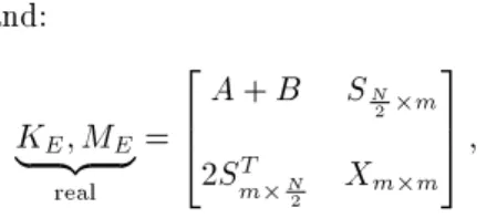
(10) and:
A special case of the Form III canonical matrix can be considered as:
[M] = 2 6 6 6 6 6 4
AN
2N2 BN2N2 SN2k
BN
2N2 AN2N2 SN2k
ST kN
2 S
T kN
2 Xkk
3 7 7 7 7 7
5; (12)
resulting in: D = A B; and:
E = 2 6 4
A + B SN 2k
2ST kN
2 Xkk
3 7
5 ; (13)
where A, B, S and X have the dimensions as shown. The matrix of this form will frequently be used in the analysis of symmetric structures.
Symmetry of Form II and III
When the matrices of the previous section are consid-ered as the Laplacian matrices of the graph models of structures, the canonical forms can be interpreted as follows.
Form II Symmetry
The axis of symmetry passes through members, and graph S has an even number of nodes. The members cut by the axis of symmetry are called link members, and their end nodes are taken as linked nodes. Link members connect the two isomorphic subgraphs, S1
and S2, to each other. For this case, two dierent
types of connection are considered. The rst one is a direct connection and the second is called a cross-connection.
In a direct connection, a typical node i in S1 is
connected to the node labeled as i+N=2 in S2by a link
member. In cross-connection, a typical pair of nodes i and j in S1 is connected to j + N=2 and i + N=2,
respectively.
Form III Symmetry
In this case, the axis of symmetry passes through nodes, while the conditions of direct or cross-connections are not fullled. The nodes on the axis of symmetry are called central nodes.
Once the types of symmetry are identied, the isomorphic subgraphs, S1 and S2, are modied such
that the union of eigenvalues of the structural matrices of the two modied subgraphs becomes the same as the eigenvalues of the entire graph, S. The process of the modications made to the subgraphs is called
the healing of the subgraphs and the entire process may be considered as the factorization of a graph. The subgraphs obtained for graph S after healing are called the factors of S.
DECOMPOSITION OF PLANAR SYMMETRIC FRAMES WITH ODD NUMBER OF SPANS
The algorithm presented in this section decomposes a symmetric structure with an odd number of spans into two factors, C and D or E and D. By obtaining the dynamic properties of each factor and considering their union, the dynamic properties of entire frames are obtained. Here, for simplicity, the axial deformations are not included and the corresponding Degrees Of Freedom (DOFs) are taken as zero.
In the following, rst Algorithm A is presented, and then the necessary new terms are introduced. Algorithm A
The algorithm for the decomposition of planar frames with an odd number of spans, with or without sway, is designed as:
Step 1: Delete all the beams crossing the axis of symmetry.
Step 2: The columns corresponding to the left part, which are connected to the eliminated beams, are doubled by tc columns. This half, for the case of non-sway frames, forms the factor C, and in the case of sway frames, together with the translation DOFs, forms the factor E. Step 3: The columns of the right half, which were
con-nected to the eliminated beams, are doubled by cc columns. This half, for the cases of sway and non-sway frames, forms the factor D, and in the case of sway frames, together with the translation DOFs, is deleted.
Denitions
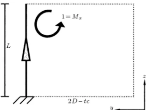
The New Element tc for Planar Case
The elements dened in the following are used in the above algorithm for doubling some columns in place of deleting the beams crossing the axis of symmetry. The new column is denoted by tc, as shown in Figure 1, and is dened as follows.
Let the properties of the deleted beam crossing the axis of symmetry be denoted by Lb, mb and EIb,
then the stiness and mass matrices of the new column, tc, will be:
Ktc= EILb b [6];
Figure 1. The new column tc, xed in Fydirection.
Mtc=mbL 3 b
420 [1]; (14)
where E is the elastic modulus, I is the moment of inertia of the cross section, m is the mass of unit length and Lb is the length of the new column.
The New Element cc for Planar Case
Again, considering the properties of the deleted beam as Lb, mb and EIb, the stiness and mass matrices of
the new column, cc, will be: Kcc=EILb
b [2]; Mcc=
mbL3b
420 [7]: (15)
This column is illustrated in Figure 2. The way these new elements, tc and cc, are dened, is explained in the subsequent section.
Potential of the Algorithm A
In this section, it is shown how Algorithm A decom-poses a symmetric planar frame with an odd number of spans into two substructures, leading to correct eigenvalues.
Algorithm for Numbering the DOFs of a Planar Frame
The following algorithms are used for numbering the DOFs of a frame, such that the corresponding stiness and mass matrices become canonical forms explained in the previous section.
Figure 2. The new column cc.
Numbering for Frames with Odd Number of Spans
Algorithm
Consider a frame with N total DOFs and p lateral translation DOFs.
1. First, we specify the symmetry line and the number of the rotation DOFs for the left part, starting from an arbitrary node and assigning 1; 2; 3; ; N=2. 2. The rotation DOFs for the right part are numbered,
such that the dierence between the numbers for the symmetric DOFs is equal to N=2.
3. The translation DOFs are numbered, starting from an arbitrary translation DOF in an arbitrary manner assigning N, N + 1, N + 2; ; N + p.
With this numbering for planar frames with an odd number of spans, the stiness and mass matrices for the non-sway case will have Form II symmetry and for a sway case will have Form III symmetry. Figure 3 shows an example of such numbering.
Numbering for Frames with Even Number of Spans
Algorithm
Consider a frame with N rotation DOFs in two sym-metric halves, r rotation DOFs in central nodes existing in the axis of symmetry, and p lateral translation DOFs.
1. First, the axis of symmetry is specied and then the rotation DOFs for the left part are numbered, starting from an arbitrary node and assigning 1; 2; 3; ; N=2.
2. The rotation DOFs for the right part are numbered, such that the dierence between the numbers for the symmetric DOFs is equal to N=2.
3. The rotation DOFs of central nodes coinciding with the axis of symmetry and all the translation DOFs
Figure 3. Numbering of the DOFs in a symmetric frame with an odd number of spans.
are numbered starting from an arbitrary DOF in an arbitrary manner and assigning N; N + 1; N + 2; ; N + p + r. Figure 4 illustrates such a numbering.
Performing this numbering, there will be a linear relationship between the stiness and mass matrices and we will have a factorization, resulting in two substructures.
On the other hand, if the numbering of the DOFs in the main structure is performed in the manner presented, the corresponding stiness and mass ma-trices become canonical forms. In the other words, in the case of non-sway frames with an odd number of spans, the problem is solved by constructing the submatrices, MC, KC and MD, KD, corresponding
to the Form II symmetry presented in the previous section. Furthermore, in the sway case of all types of frame, with either an odd or even number of spans, and in the case of non-sway frames with an even one, the problem is solved by forming submatrices, MD, KD
and f(ME; m), f(KE; m), corresponding to Form III
symmetry, as presented in the previous section. For a structure with an even number of spans, m is the total number of the translation DOFs (if they exist) and rotation DOFs of central nodes, i.e. m = r + p, where r and p are previously dened.
If the numbering of the DOFs in the main struc-ture is performed in the manner presented, then the corresponding stiness and mass matrices will have the following forms:
K; M = 2 6 6 6 6 6 4
AN
2N2 BN2N2 SN2m
BN
2N2 AN2N2 SN2m
ST mN
2 S
T mN
2 Xmm
3 7 7 7 7 7 5 ) K| {z }D; MD
real
= A B;
Figure 4. Numbering of the DOFs in a symmetric frame with an even number of spans.
and: KE; ME
| {z }
real
= 2 6 4
A + B SN 2m
2ST mN
2 Xmm
3 7
5 ; (16)
which are the same as Equation 12.
However, the stiness and mass matrices of sub-structure E in Algorithm A diering to submatrix E in Equation 14 are obtained as:
KD; MD
| {z }
algorithm
= A B; and:
KE; ME
| {z }
algorithm
= 2
4A + B S
ST X=2
3
5 : (17)
In this algorithm, the stiness and mass matrices of factor E are not the same as those obtained from the partitioning of the corresponding matrices of the original structure, as presented in Equations 6 or 9 and 10. However, the responses consisting of the determinant and eigenvalues are identical as proved in the following.
The Function f(A; m) and Proof of a Theorem Function f(A; m)
Consider A as a matrix. The function f(A; m) multi-plies the last m rows of A by 2.
An example is provided in the following:
A = 2 6 6 6 6 4
3 3 6 9 5 7 3 5 1 9 4 6 2 8 6 5 4 1 7 7 6 5 9 2 5 3 7 7 7 7 5;
f(A; 2) = 2 6 6 6 6 4
3 3 6 9 5
7 3 5 1 9
4 6 2 8 6
10 8 2 14 14
12 10 18 4 10 3 7 7 7 7 5;
f(A; 3) = 2 6 6 6 6 4
3 3 6 9 5
7 3 5 1 9
8 12 4 16 12
10 8 2 14 14
12 10 18 4 10 3 7 7 7 7 5: Theorem
If m is a number of rows of a matrix and K and M are arbitrary matrices, then the eigenvalues of M 1 K
Proof
When a row or column of a matrix is multiplied by a constant number, then the determinant is multiplied by the same number. Thus, employing function f, we have:
det(f(K; m)) = 2mdet K;
det(f(M; m)) = 2mdet M: (18)
If and ' are the eigenvalues and eigenvectors of
M 1 K:
M 1 K' = ': (19)
Pre-multiplying by M leads to:
M M 1K' = M': (20)
Thus:
K' = M'; (21)
or:
(K M) ' = 0: (22)
Hence:
det(K M) = 0: (23)
On the other hand, we have:
det(f(K; m) f(M; m))=2mdet(K M)=0:
(24) Therefore:
eig([f(M; m)] 1f(K; m))==eig(M 1 K):
(25) In dynamic analysis, can be considered as !2
result-ing in:
K !2M' = 0; (26)
where ! are natural frequencies of a structure. Thus, the theorem can be restated as follows.
If m is an integer number dened previously and K and M are the stiness and mass matrices of a structure, then the natural frequencies obtained from matrices M and K and those obtained from matrices f(K; m) and f(M; m) are identical.
Therefore, we can conclude that the eigenvalues obtained from the stiness and mass matrices of each substructure, such as E in the above relationship (Equation 17), are equal to those obtained from the main structure (Equation 16), i.e:
KD
|{z}
real
= f( K| {z }D; m algorithm
);
and: MD
|{z}
real
= f( M| {z }D; m algorithm
); (27)
KE
|{z}
real
= f( K| {z }E; m algorithm
); and:
ME
|{z}
real
= f( M| {z }E; m algorithm
): (28)
It is important to note that we have obtained sub-structures for which the stiness and mass matrices are symmetric and in order to obtain their eigenvalues, one does not need to utilize function f. At the same time, the factorization can be performed in a simple manner.
Properties of the Columns tc and cc
The properties of the new columns are obtained con-sidering the inter-relation of the DOFs of the members. For the frames with an odd number of spans, where the axis of symmetry passes through beams, the eect of the deleted beams should be included in the decom-posed subgraphs. Adding the new columns serves as a means for transferring the properties of the main structure into the decomposed substructures. These operations are healings which change the subgraphs into the factors. The new columns introduced here are more eective than using springs, masses, and other devices as have been used in [17].
If we can construct substructures with stiness and mass matrices corresponding to the Form II canon-ical form, then we can form the factors.
If the numbering of DOFs is performed corre-sponding to canonical Form II, then submatrix B will represent the relation between the DOFs of the right and left side of the frame and submatrix A represents the relation between the DOFs of each half of the structure. A, B, C and D are shown in Equations 4 and 6.
In general, for a beam-column with one rotational DOF per node, we have:
K =EI
L
4 2 2 4
; M =mL3
420
4 3
3 4
:
(29) Considering the relationship between the DOFs of the connecting beams, it becomes obvious that entries (1,1) and (1,2) in the mass and stiness matrices of substructures C and D should be added and subtracted,
respectively:
C : K = EIL [4 + 2] = EIL [6]; M = mL4203 [4 + ( 3)] = mL4203 [1]; D : K = EIL [4 2] = EIL [2];
M = mL4203 [4 ( 3)] = mL4203 [7]: (30) It is obvious that the length and the elastic properties in these relationships correspond to the connecting beams, which are supposed to be deleted:
Ktc= EILb b [6];
Mtc= mbL 3 b
420 [1]; Kcc= EILb
b [2];
Mcc= mbL 3 b
420 [7]: (31)
In this way, the properties of the new columns are obtained.
Now, if we want to use this algorithm, submatrices D and E can be obtained much easier than the previous methods wherein we had to add masses and springs [17]. Another advantage of this algorithm is that, unlike previous methods, the substructures in both sway and non-sway cases are similar, and the only dierence is in a non-sway case for the left half substructure of the frame where we have translation DOFs.
Example 1
The symmetric frame shown in Figure 5 is considered. This is constrained against sway and has only 2
Figure 5. A symmetric frame with two DOFs.
rotation DOFs as shown in the gure.
The distribution of mass in the link beam that crosses the axis of symmetry should also be symmetric. According to Algorithm A, the decomposi-tion of the frame is obtained in a step by step manner, whereas, in previously developed methods, the factors were obtained by adding springs and masses [17].
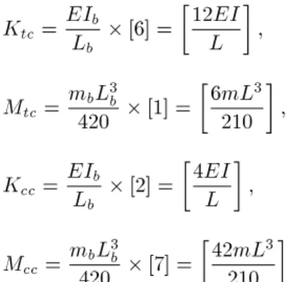
The properties of the added columns (Figure 6) are as follows:
Ktc= EILb
b [6] =
12EI
L
; Mtc= mbL
3 b
420 [1] =
6mL3
210
; Kcc= EILb
b [2] =
4EI
L
; Mcc= mbL
3 b
420 [7] =
42mL3
210
:
Now, the stiness and mass matrices of factors C and D are formed as:
KC=
4EI
L +
12EI L
=
16EI
L
; MC =
mL
420 4L2+ 6mL3
210
=
8mL3
210
; !2= X;
) !1=
r 420EI
mL4 ;
and: KD=
4EI
L +
4EI L
=
8EI
L
; MD=
mL
420 4L2+ 42mL3
210
=
44mL3
210
;
!2= X
) !2=
r 420EI 11mL4;
and the natural frequencies are easily obtained. Example 2
The frame shown in Figure 7 has 10 DOFs and has Form II symmetry. The factors are constructed as shown in Figure 8.
The stiness and mass matrices of the added columns are as follows:
tc1: ) Ktc1 =
EIb
Lb [6] = [2EI];
Mtc1 =
mbL3b
420 [1] =
9m 140
; cc1: ) Kcc1 =
EIb
Lb [2] =
2EI
3
; Mcc1=
mbL3b
420 [7] =
9m 20
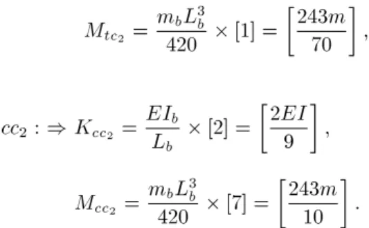
; tc2: ) Ktc2 =
EIb
Lb [6] =
2EI
3
;
Figure 7. A symmetric frame with 10 DOFs.
Figure 8. Factors of the frame of Figure 7.
Mtc2 =
mbL3b
420 [1] =
243m 70
;
cc2: ) Kcc2 =
EIb
Lb [2] =
2EI
9
; Mcc2=
mbL3b
420 [7] =
243m 10
:
The stiness and mass matrices of factors C and D are constructed as:
KC = EI
2 6 6 6 6 6 6 6 6 6 6 6 6 4 4
3 +44+44 24 24 2
4 44+44 0 2
4 0 43+44+43 +44
0 2
4 24
0 0 2
3
0 0
2
4 0
2
4 23 4
4+44+23 0
0 4
3+43+ 2
3 7 7 7 7 7 7 7 7 7 7 7 7 5 = 2EI 2 6 6 6 6 6 6 6 6 6 6 6 6 4
5=3 1=4 1=4 0 0
1=4 1 0 1=4 0
1=4 0 7=3 1=4 1=3
0 1=4 1=4 4=3 0
0 0 1=3 0 7=3
3 7 7 7 7 7 7 7 7 7 7 7 7 5 ;
MC= 420m
2 6 6 6 6 6 6 6 6 6 6 6 6 4
620 192 192 0 0
192 512 0 192 0
192 0 728 192 81
0 192 192 1241 0
0 0 81 0 243
3 7 7 7 7 7 7 7 7 7 7 7 7 5 ;
KD= EI 2 6 6 6 6 6 6 6 6 6 6 6 6 4 4
3 +44+44 24 24 2
4 44+44 0 2
4 0 43+44+43 +44
0 2
4 24
0 0 2
3
0 0
2
4 0
2
4 23 4
4+44+29 0
0 4
3+43+23
3 7 7 7 7 7 7 7 7 7 7 7 7 5 = 2EI 2 6 6 6 6 6 6 6 6 6 6 6 6 4
5=3 1=4 1=4 0 0
1=4 1 0 1=4 0
1=4 0 7=3 1=4 1=3
0 1=4 1=4 10=9 0
0 0 1=3 0 5=3
3 7 7 7 7 7 7 7 7 7 7 7 7 5 ;
MD= 420m
2 6 6 6 6 6 6 6 6 6 6 6 6 4
620 192 192 0 0
192 512 0 192 0
192 0 728 192 81
0 192 192 5615 0
0 0 81 0 405
3 7 7 7 7 7 7 7 7 7 7 7 7 5 :
In this way, the natural frequencies and natural modes of this frame with 10 DOFs are obtained using the equation of motion of two factors each having 5 DOFs, as:
det[KC !2MC]55= 0;
leading to:
!1=
r 0:6EI
m ;
!2=
r 1:42EI
m ;
!3=
r 2:15EI
m ;
!4=
r 5:24EI
m ;
!5=
r 9:56EI
m ;
and:
det[KD !2MD]55= 0;
leading to: !6=
r 0:15EI
m ;
!7=
r 1:1EI
m ;
!8=
r 2EI
m ; !9=
r 3:52EI
m ;
!10=
r 5:57EI
m :
Example 3
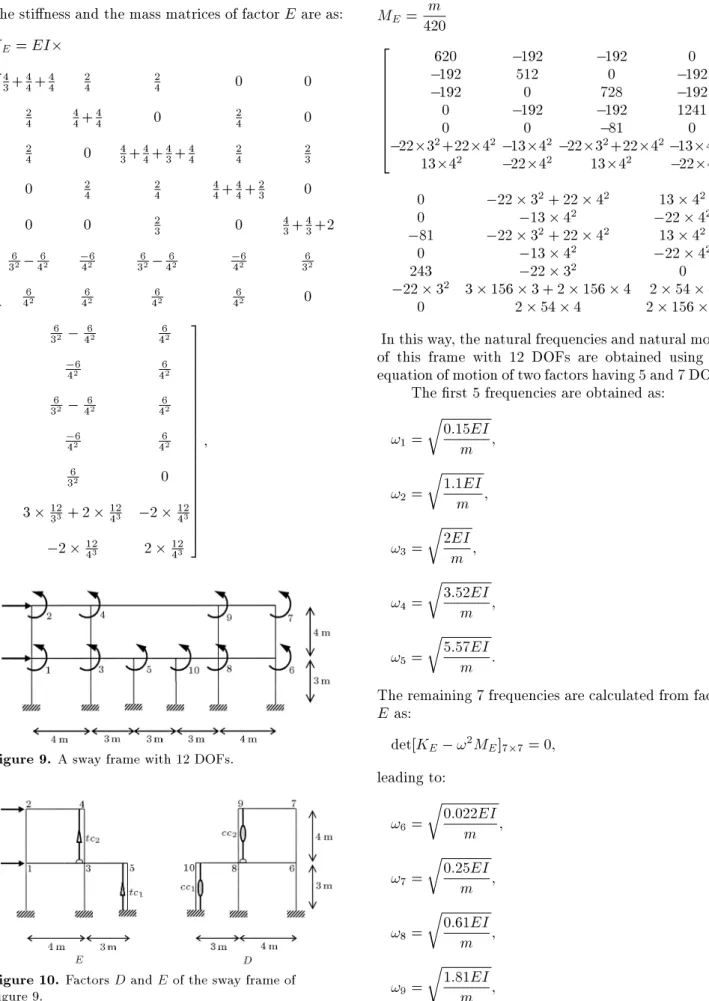
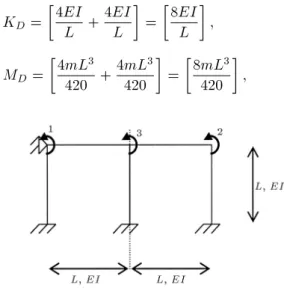
Consider the sway frame shown in Figure 9, having 12 DOFs. The factors are shown in Figure 10.
The natural frequencies are similar to those of Example 2. Here, there is no need to solve equation det[KD !2MD]55 = 0 for nding the eigenvalues.
The formation of factor D can be avoided: cc1: ) Kcc1 =
EIb
Lb [2] =
2EI
3
; Mcc1 =
mbL3b
420 [7] =
9m 20
; cc2: ) Kcc2 =
EIb
Lb [2] =
2EI
9
; Mcc2 =
mbL3b
420 [7] =
243m 10
:
The stiness and the mass matrices of factor E are as: KE= EI
2 6 6 6 6 6 6 6 6 6 6 6 6 6 6 6 6 6 6 6 6 4
4
3+44+44 24 24 0 0 2
4 44+44 0 24 0 2
4 0 43+44+43+44 24 23
0 2
4 24 44+44+23 0
0 0 2
3 0 43+43+2 6
32 462 426 362 462 426 362
6
42 462 462 462 0
6
32 462 462
6
42 462
6
32 462 462
6
42 462
6
32 0
3 12
33 + 2 1243 2 1243
2 12
43 2 1243
3 7 7 7 7 7 7 7 7 7 7 7 7 7 7 7 7 7 7 7 7 5 ;
Figure 9. A sway frame with 12 DOFs.
Figure 10. Factors D and E of the sway frame of Figure 9.
ME =420m
2 6 6 6 6 6 6 6 6 4
620 192 192 0
192 512 0 192
192 0 728 192
0 192 192 1241
0 0 81 0
2232+2242 1342 2232+2242 1342
1342 2242 1342 2242
0 22 32+ 22 42 13 42
0 13 42 22 42
81 22 32+ 22 42 13 42
0 13 42 22 42
243 22 32 0
22 32 3 156 3 + 2 156 4 2 54 4
0 2 54 4 2 156 4
3 7 7 7 7 7 7 7 7 5 :
In this way, the natural frequencies and natural modes of this frame with 12 DOFs are obtained using the equation of motion of two factors having 5 and 7 DOFs.
The rst 5 frequencies are obtained as: !1=
r 0:15EI
m ;
!2=
r 1:1EI
m ;
!3=
r 2EI
m ; !4=
r 3:52EI
m ;
!5=
r 5:57EI
m :
The remaining 7 frequencies are calculated from factor E as:
det[KE !2ME]77= 0;
leading to: !6=
r
0:022EI
m ;
!7=
r 0:25EI
m ;
!8=
r 0:61EI
m ;
!9=
r 1:81EI
!10=
r 2:97EI
m ;
!11=
r 5:67EI
m ;
!12=
r
10:27EI
m :
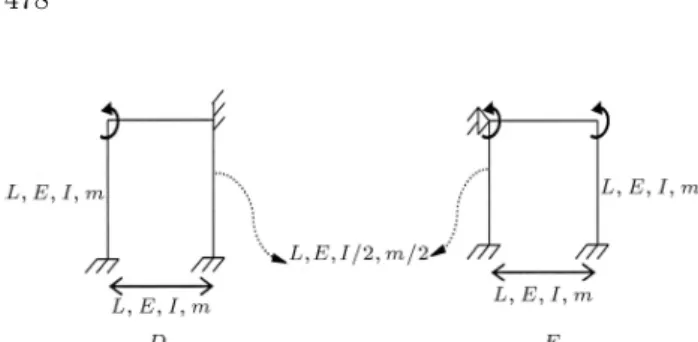
The factors of the main frame in the case of sway and non-sway are identical (Figure 11).
Only factor E has the additional translation DOF. Thus, for calculating the responses of frames in sway and non-sway cases, instead of solving a problem with n n and (n + m) (n + m) matrices, we need to solve three problems corresponding to n=2 n=2, n=2 n=2 and (n=2 + m) (n=2 + m) matrices (Figure 12). DECOMPOSITION OF SYMMETRIC
PLANAR FRAMES WITH EVEN NUMBER OF SPANS
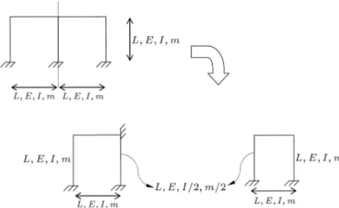
According to the algorithm, each symmetric structure with an even number of spans is decomposed into two factors without introducing a new element. By obtaining the dynamic properties of each factor and considering the union of the results, one can obtain the dynamic properties of the entire structure.
Figure 11. Factors of the frame in non-sway and sway cases.
Figure 12. Three factors to be considered for the solution.
Denitions
A central element is dened as a column which co-incides with the axis of symmetry. Central nodes are taken as the nodes that coincide with the axis of symmetry.
Algorithm B
This algorithm is simple and consists of the following steps.
Step 1: Divide the frame into two halves from the axis of symmetry, such that the moment of inertia for the central column and the mass of their unit length, m, are reduced to half.
Step 2: Fix the central nodes in the left half. This half is factor D and the right half forms factor E. All aspects proved previously are applicable to this algorithm. Thus, the results consisting of the deter-minant and eigenvalues of free vibration from decom-position due to this algorithm are identical to those of the main frame, as was desired. Therefore, we solve the main eigenproblem by constructing submatrices, KD, MD and KE, ME. In fact, factors D and E
obtained by this algorithm have the properties of the entire structure.
Example 4
Consider the frame shown in Figure 13, which is constrained against sway. This frame has 3 DOFs. It is assumed that the frame has symmetric elastic properties with respect to the two planes of symmetry. Factors D and E are obtained using Algorithm B, step by step, as shown in Figure 14. These factors can be considered, as shown in Figure 15.
The submatrices corresponding to these two fac-tors are obtained and their characteristic equations lead to the eigen-frequencies required as:
KD=
4EI
L +
4EI L
=
8EI
L
; MD=
4mL3
420 + 4mL3
420
=
8mL3
420
;
Figure 14. The factors of the frame of Figure 11.
Figure 15. Alternative illustration of the factors of the frame of Figure 11.
det[KD !2MD] = 0 ) !1=
r 420EI
mL4 ;
KE =
2 4
4EI
L +4EIL 2EIL 2EI
L 4EIL +4(EI=2)L
3 5
= 2 4
4EI
L +4EIL 2EIL 2EI
L 4EIL +4(EI=2)L
3 5 ;
ME=
2 6 4
4mL3
420 +4mL
3
420 3mL
3
420 3mL3
420 4mL
3
420 +4(m=2)L
3
420
3 7 5 ; det[KE !2ME] = 0;
!2=
r 525EI
mL4 ;
and: !3=
r 378EI
mL4 :
Example 5
Consider the frame with an even number of spans, as shown in Figure 16, where the frame has 10 DOFs without side sway and 12 DOFs with side sway:
In the case of non-sway, factors D and E are obtained, as shown in Figure 17.
In this case, the eigensolution of a 10 10 matrix is transformed into the eigensolution of two 4 4 and 6 6 matrices.
Figure 16. A frame with 4 spans.
Figure 17. Factors D and E for the non-sway frame.
Figure 18. Factors D and E for the sway frame.
In the sway case, factors D and E are obtained, as shown in Figure 18.
The factors of the main frame in the case of sway and non-sway are identical. Only factor E has the translation DOF.
Decomposition for Static and Dynamic Analysis in the Case of Symmetric Loading In this section, a symmetric frame is decomposed into two factors. For static analysis, the decomposition of the frame is shown in Figure 19.
For dynamic analysis, the decomposition is illus-trated in Figure 20.
CONCLUDING REMARKS
The decomposition and healing processes presented in this article reduce the dimensions of the matrices for
Figure 19. Decomposition for the static analysis.
Figure 20. Decomposition for dynamic analysis.
dynamic analysis of the symmetric frames. Therefore, for large-scale problems, the accuracy of calculation increases and the cost of computation decreases.
It can be observed that for symmetric frames, one of the factors is common in both way and non-sway cases. Therefore, if a frame has n symmetric DOFs, then, in both sway and non-sway cases, we will have common results. As an example, for a ten-storey frame with Form II symmetry, the natural frequencies can be obtained by three matrices of dimensions 4545, 4545 and 5555 in place of two matrices of dimensions 100 100 and 9090. This results in a considerable saving in computational time. The saving becomes more obvious when large-scale structures are considered.
In this paper, only eigenvalues are calculated, since the eigenvectors for the presented canonical forms can easily be obtained using the simple methods devel-oped in [15].
The present method can also be applied to similar eigensolution problems such as stability analysis of symmetric frames for calculating the critical loads of frames.
NOMENCLATURE
K stiness matrix of a member or a structure
M mass matrix of a member or a structure
m mass for one meter of the member L length of the member
E elastic modules
I moment inertia of the member ! natural frequencies
' vibration modes
REFERENCES
1. Kangwai, R.D., Guest, S.D. and Pellegrino, S. \An Introduction to the analysis of symmetric structures", Comput. Struct., 71, pp. 671-688 (1999).
2. Gruber, B., Symmetries in Science VIII, Plenum Press, NY (1995).
3. Glockner, P.G. \Symmetry in structural mechanics", J. Struct. Div., ASCE, 99, pp. 71-89 (1973).
4. Zingoni, A. \Group-theoretical applications in solid and structural mechanics: a review", Chapter 12 in Computational Structures Technology, BHV Topping and Z. Bittnar, Eds., Saxe-Coburg Publication, UK (2002).
5. Zingoni, A., Pavlovic, M.N. and Zlokovic, G.M. \A symmetry-adapted exibility approach for multi-storey space frames: General outline and symmetry-adapted redundants", Struct. Eng. Rev., 7, pp. 107-119 (1995).
6. Livesley, R.K., Mathematical Methods for Engineers, Ellis Horwood Series in Mathematics and its Applica-tions, UK (1989).
7. Jennings, A. and McKeown, J.J., Matrix Computation, John Wiley and Sons, UK (1992).
8. Bathe, K.J. and Wilson, E.L., Numerical Methods for Finite Element Analysis, Englewood Clis, Prentice Hall, USA (1976).
9. Kron, G. \Diakoptics, piecewise solution of large-scale systems", Electrical J. (London), A serial of 20 chapters from June 7 (1957) to February 13 (1959). 10. Prezemieniecki, J.S. \Matrix structural analysis of
substructures", AIAA J., 1, pp. 138-147 (1963). 11. Cuppen, J.J.M. \A divide and conquer method for the
symmetric tridiagonal eigenproblem", Numer. Math., 36, pp. 177-195 (1981).
12. Kaveh, A. and Sayarinejad, M.A. \Eigensolutions for matrices of special patterns", Commun. Numer. Methods Eng., 19, pp. 125-136 (2003).
13. Kaveh, A. and Sayarinejad, M.A. \Eigensolution of specially structured matrices with hyper-symmetry", Inter. J. Numer. Methods Eng., 67(7), pp. 1012-1043 (2006).
14. Kaveh, A., Structural Mechanics: Graph and Matrix Methods, Research Studies Press (John Wiley), Exeter, UK, 3rd Ed. (2004).
15. Kaveh, A. and Sayarinejad, M.A. \Eigensolutions for factorable matrices of special patterns", Commun. Numer. Methods Eng., 20, pp. 133-146 (2004).
16. Kaveh, A. and Sayarinejad, M.A. \Graph symmetry in dynamic systems", Comput. Struct., 82(23-26), pp. 2229-2240 (2004).
17. Kaveh, A. and Salimbahrami, B. \Eigensolutions of symmetric frames using graph factorization", Com-mun. Numer. Methods Eng., 20, pp. 889-910 (2004). 18. Rahami, H. and Kaveh, A. \Forced vibration of
sym-metric structures", Commun. Numer. Methods Eng., 24(11), pp. 1393-1406 (2008).
19. Kaveh, A. and Dadfar, B. \Eigensolution for stabil-ity analysis of planar frames, by graph symmetry", Comput.-Aided Civil Infrastruct. Eng., 22, pp. 267-275 (2007).
20. Kaveh, A. and Salimbahrami, B. \Buckling load of symmetric frames using canonical forms", Comput. Struct., 85(11), pp. 1420-1430 (2007).