REAL-TIME OBJECT REMOVAL IN AUGMENTED REALITY
A Thesis presented to
the Faculty of California Polytechnic State University, San Luis Obispo
In Partial Fulfillment
of the Requirements for the Degree Master of Science in Computer Science
by Tyler Dahl
c
2018
Tyler Dahl
COMMITTEE MEMBERSHIP
TITLE: Real-Time Object Removal in Augmented
Reality
AUTHOR: Tyler Dahl
DATE SUBMITTED: June 2018
COMMITTEE CHAIR: Christian Eckhardt, Ph.D. Professor of Computer Science
COMMITTEE MEMBER: Maria Pantoja, Ph.D.
Professor of Computer Science
COMMITTEE MEMBER: Franz J. Kurfess, Ph.D.
ABSTRACT
Real-Time Object Removal in Augmented Reality Tyler Dahl
Diminished reality, as a sub-topic of augmented reality where digital information is overlaid on an environment, is the perceived removal of an object from an environ-ment. Previous approaches to diminished reality used digital replacement techniques, inpainting, and multi-view homographies. However, few used a virtual representation of the real environment, limiting their domains to planar environments.
This thesis provides a framework to achieve real-time diminished reality on an augmented reality headset. Using state-of-the-art hardware, we combine a virtual representation of the real environment with inpainting to remove existing objects from complex environments.1
Our work is found to be competitive with previous results, with a similar quali-tative outcome under the limitations of available technology. Additionally, by imple-menting new texturing algorithms, a more detailed representation of the real envi-ronment is achieved.
ACKNOWLEDGMENTS
Thanks to:
• My parents, Derek and Michelle, for their constant support, love, and belief that I can accomplish whatever I set my mind to
• My sister, Courtney, for her constant support, love, and encouragement
• God, for placing me at Cal Poly and giving me the strength to finish strong • My friends and relatives, for their prayers and encouragement throughout this
process
• Zoe Wood, for igniting my love of computer graphics and pushing me to pursue challenging projects
• Christian Eckhardt, for establishing the Mixed Reality Lab and providing me with the tools necessary to complete this thesis
• Cal Poly, for an amazing computer science program
TABLE OF CONTENTS
Page
LIST OF TABLES . . . viii
LIST OF FIGURES . . . ix
CHAPTER 1 Introduction . . . 1
2 Background . . . 6
2.1 Region Selection . . . 6
2.1.1 Manual . . . 6
2.1.2 Semi-Automatic . . . 7
2.1.3 Automatic . . . 7
2.2 Region Tracking . . . 7
2.2.1 2D Features . . . 8
2.2.2 SLAM . . . 9
2.3 Region Diminishing . . . 9
2.3.1 Replacing . . . 10
2.3.2 Inpainting . . . 10
2.3.3 See-through . . . 12
2.4 Proposed Solution . . . 14
2.5 Related Work . . . 15
3 Architecture . . . 17
3.1 Spatial Mapping . . . 17
3.2 3D Post-Processing . . . 18
3.3 Texturing . . . 18
3.4 Object Selection and Tracking . . . 19
3.5 Object Removal (Diminishing) . . . 19
3.6 2D Post-Processing . . . 20
4 Implementation . . . 21
4.1 Hardware . . . 21
4.1.2 Microsoft HoloLens . . . 22
4.1.3 Intel RealSense . . . 24
4.1.4 Other Hardware . . . 25
4.2 Development Environment . . . 27
4.2.1 Unity . . . 28
4.2.2 Unreal Engine . . . 29
4.2.3 DirectX . . . 29
4.3 Diminished Reality Pipeline . . . 30
4.3.1 Spatial Mapping . . . 31
4.3.2 3D Post-Processing . . . 33
4.3.3 Texturing . . . 35
4.3.4 Object Selection and Tracking . . . 50
4.3.5 Object Removal (Diminishing) . . . 51
4.3.6 2D Post-Processing . . . 53
5 Results . . . 56
5.1 Internal Comparisons . . . 56
5.2 Previous Work Comparisons . . . 58
6 Future Work . . . 61
7 Conclusion . . . 63
BIBLIOGRAPHY . . . 64
APPENDICES A Projective Texture Mapping Shader . . . 72
LIST OF TABLES
Table Page
LIST OF FIGURES
Figure Page
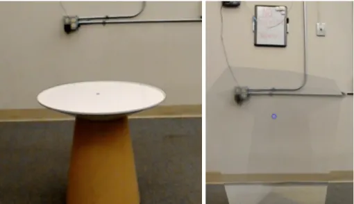
1.1 Diminishing a table with our solution. Left image is the table before
diminishing. Right image is after the table is removed. . . 4
2.1 A homography between two frames taken from different perspectives [55]. . . 8
2.2 Simultaneous localization and mapping (SLAM) [34]. . . 9
2.3 Google Translate app replaces text with a different language [41]. . 10
2.4 Inpainting a bungee jumper [40]. . . 11
2.5 Comparison of inpainting from different viewpoints [30]. Top: input images. Middle: inpainting multiple planes. Bottom: inpainting a single plane. . . 12
2.6 Seeing through a car using multiple cameras [43]. Top left image is from the back car’s perspective. Top right image is from the front car’s perspective. . . 13
4.1 The Microsoft HoloLens [12]. . . 22
4.2 HoloLens hardware specifications [44]. . . 24
4.3 Intel RealSense Depth Camera D400-Series [9]. . . 25
4.4 Intel RealSense Depth Camera D435 Specifications [17]. . . 26
4.5 Other hardware platforms. From left to right: Kinect v2, Meta 2, Magic Leap One [5, 11, 6]. . . 27
4.6 Triangle mesh of an environment obtained via spatial mapping [7]. . 31
4.7 Low, medium, and high triangle densities [16]. . . 32
4.8 An object connected to the floor before post-processing. . . 34
4.9 Checkerboard normal shading. . . 35
4.10 Projective texture mapping with a single projector [25]. . . 36
4.11 The problem of back/reverse projection [25]. . . 39
4.12 The problem of projecting onto triangles that the projector can’t see [26]. . . 39
4.14 The weighting function used in view-dependent texture mapping. Weights w1 and w2 are inversely proportional to the magnitude of the angles a1 and a2 [23]. . . 41 4.15 Spatial mapping textured with three overlapping images of the real
environment. . . 43 4.16 A volume element known as a voxel [8]. . . 44 4.17 An octree of varying resolutions [4]. . . 44 4.18 Convex hull generation from a collection of points. Left is the
col-lection of points. Right is the convex hull around the colcol-lection of points. . . 52 4.19 Spatial mapping of small objects on a table. Left is the original
image. Right is the spatial mapping at 500 triangles per cubic meter. 53 4.20 Inpainting of small strokes in an image [22]. . . 54 4.21 Inpainting green pixels. . . 55 5.1 Simple vs complex environment. Left is a simple environment
con-taining a single table. Right is a complex environment concon-taining many small stools. . . 57 5.2 Result of removing a chair from the diminished reality method
pro-posed by Simpson [47]. . . 58 5.3 Result of removing a cereal box from the diminished reality method
Chapter 1 INTRODUCTION
Our perception of reality is being reshaped. Much like the industrial revolution forever changed society through the rise of machines, the digital revolution is changing society through the rise of visual, interactive data. This data is accessible through interaction with 2D screens in the form of smartphones, tablets, computers, and TVs. However, new developments in virtual reality make it feasible to interact with this data in 3D space.
Virtual reality (VR) allows us to become completely immersed in a fully artificial, digital environment [42]. Current VR technology displays digital content onto a head-mounted device with two screens, one for each eye, where a stereoscopic image is displayed to trick the brain into perceiving depth. Users can interact with virtual objects through controllers specifically designed for such interaction. The experiences users have within the virtual environment are often described as highly immersive. Sensations range from experiencing virtual movement to altitude panic [13].
The primary focus of recent investigations in virtual reality have been the side effects of this high level of immersion, specifically motion sickness. If a user moves within the virtual environment while their physical body remains at rest, their brain registers a certain acceleration and tries to compensate, leading to an uncomfortable disorientation. The same sensation is felt in the opposite scenario, when e.g. sitting in a static environment while the body senses movement such as carsickness and seasickness. This can result in nausea, dizziness, and fatigue, reducing time spent in the virtual environment [46].
envi-ronment in sync with their physical body. This allows the user to control their virtual counterpart in a natural way by walking around their real environment. However, this presents several limitations, such as the user colliding with physical objects and a virtual world constrained by the size of the real environment. Other strategies have been developed to reduce motion sickness, such as teleporting a person’s virtual counterpart between locations and walking in place. These strategies allow users to experience the fun and immersion of virtual reality without the unwanted side effects. Another technology, called augmented reality, provides a similar experience to virtual reality but without the motion sickness.
Augmented reality (AR) allows us to interact with digital content while also remaining aware of the real environment. Current AR technology displays digital content onto a see-through display, overlapping real world information with digital content. In the simplest form of augmented reality, digital information is displayed on billboards within the user’s field of view. Digital content cannot interact with the real world. This form of augmented reality became popular through the introduc-tion of heads-up displays (HUD). Originally developed to prevent military pilots from looking down to view instrument data, HUDs have also been used in popular modern products such as Google Glass.
Recent advancements in computer vision and depth sensing are enabling a more advanced form of augmented reality, where digital content is not confined to a static location. These advancements allow the pinpointing of real object positions and properties (size, color) for a fluid interaction between virtual and real elements.
provides an immersive experience similar to virtual reality.
Though this technology is still in its infancy, industry-leading tech companies are actively pursuing its development [32]. Mobile devices are dominating the market in the near-term with head-mounted devices predicted to dominate in the future. In 2015, the first head-mounted mixed reality device, the HoloLens, was released by Microsoft. In 2017, mobile mixed reality experiences became common with the introduction of ARKit and ARCore by Apple and Google respectively. The future is one where digital content seamlessly blends with our real world.
The primary vision touted by futurists is a pair of augmented reality glasses powerful enough to replace smartphones. To realize this future, technology needs to shrink and faster algorithms need to be developed. Consumers want a device that enhances their life without the need to change their habits. In order to seamlessly blend digital content with the real world, digital content ought to not just be added to the world, but real content ought to be digitally removed.
graffiti from view, obscuring secret agents from webcams, seeing through walls on a construction site, seeing a patient’s internal organs during surgery, or removing unwanted objects in photographs.
For this thesis, we chose to research diminished reality. With the goal of eventual consumer adoption, an ideal diminished reality solution is one that works in any environment without complex setup. Our research question is therefore: ”Can a diminished reality solution be developed with current hardware which works in any environment in real-time, with no prior knowledge of the environment?”
Figure 1.1: Diminishing a table with our solution. Left image is the table before diminishing. Right image is after the table is removed.
Our solution is a diminished reality prototype created on the Microsoft HoloLens which successfully removes an object in an unseen environment in real-time. See Figure 1.1. Our contribution to the field of diminished reality is a pipeline that can be used as a basis upon which future diminished reality solutions can be developed. Each section of the pipeline can be replaced with newer technologies and algorithms as they become available to enhance the diminished result.
Chapter 2 BACKGROUND
The term ”diminished reality” was first coined in 1999 by Mann in his concept of mediated reality which included AR, MR, and DR [35]. In practice, diminished reality is achieved when applying the following three steps to a video feed: region selection, region tracking, and region removal. The following sections will explore various techniques that have been explored for each step.
2.1 Region Selection
Before an object can be removed, there must first be a way to specify the object. Techniques used by previous diminished reality approaches range from completely manual selection to completely automated selection. The more accurate the selection, the more realistic the removal.
2.1.1 Manual
2.1.2 Semi-Automatic
Semi-automatic region selection methods require the user to provide minimal input prior to generating the selected region. Both region expansion and region shrinking algorithms exist. Herling and Broll use a region shrinking method to fit the selected region to the contour of the dominant object within an initial circle drawn by the user [28]. Additional padding was added to account for errors in contour detection. Simpson used a region expansion method to segment an object from a mesh given a 3D point on the object [47]. The selected object was found by traversing triangles connected to the given point until a plane was detected. Semi-automatic selection methods allow complex shapes to be quickly selected and provide impressive results.
2.1.3 Automatic
Automatic region selection requires no real-time input from the user. Region selection is performed immediately and automatically, sometimes using offline input. Nakajima et al. use automatic region selection by removing all objects of a chosen category specified offline [38]. Objects of the chosen category are detected using a neural network and segmented from a global point cloud. Automatic selection methods allow immediate diminished results, but are not practical in all scenarios. Some user input is preferred.
2.2 Region Tracking
used.
2.2.1 2D Features
Region tracking with 2D features involves the detection and matching of small pat-terns within pairs of images. Features that can be tracked include edges, corners, blobs, ridges, and other shapes learned by neural networks. Using the difference be-tween tracked features within two images, a homography is calculated and used to transform one image to the perspective of the other. See Figure 2.1. This transform is also used to update the selected region’s position in each frame. Many diminished reality methods use 2D image features to update the selected region per frame. For example, Herling and Broll used 2D features to detect the contour of an object and update the selected region to match the contour every frame [28].
2.2.2 SLAM
Region tracking with 3D positions is performed through simultaneous localization and mapping (SLAM) techniques. SLAM techniques use RGB plus depth (RGB-D) data per pixel to create a map of the environment and calculate the camera’s position within the map. See Figure 2.2. Visual-SLAM techniques use only RGB data per pixel and calculate depth from changes in 2D features over time. Visual-SLAM is less accurate than SLAM, but doesn’t require a sensor capable of acquiring depth data. The 3D positions of the selected object are then transformed to screen space every frame to obtain the updated selected region. Kawai et al. used visual-SLAM to track an object’s position within an environment and inpaint detected planes [30]. SLAM techniques are less often used in diminished reality due to the need for specialized sensors and computationally expensive algorithms.
Figure 2.2: Simultaneous localization and mapping (SLAM) [34].
2.3 Region Diminishing
The result is the original image where the selected region is diminished. There are three categories of object removal: replacing, inpainting, and see-through.
2.3.1 Replacing
Figure 2.3: Google Translate app replaces text with a different language [41].
Object removal techniques that cover or replace the selected region are the sim-plest form of diminished reality. The selected region is diminished by hiding it behind a virtual object large enough to cover the entire region. An example of this is imple-mented in the Google Translate iOS and Android app [1]. The app replaces text in any picture taken by the user with text of a chosen language. A virtual rectangle is displayed in front of the existing text to hide it and then text of the chosen language is displayed in front of the virtual rectangle. See Figure 2.3. This approach works well when the user does not need to see the background behind the selected object.
2.3.2 Inpainting
and often repeated. By repeating nearby patterns in front of the selected region, the object will appear to vanish. See Figure 2.4. In 2010, Herling and Broll demonstrated the first real-time inpainting algorithm capable of running on commodity hardware with simple setup, named PixMix [27, 28]. In 2017, Iizuka et al. further showed that it was possible to use a neural network to learn and repeat patterns from similar images to provide a realistic diminished result [29].
Figure 2.4: Inpainting a bungee jumper [40].
Figure 2.5: Comparison of inpainting from different viewpoints [30]. Top: input images. Middle: inpainting multiple planes. Bottom: inpainting a single plane.
2.3.3 See-through
Figure 2.6: Seeing through a car using multiple cameras [43]. Top left image is from the back car’s perspective. Top right image is from the front car’s perspective.
Other approaches use a single camera from multiple viewpoints or previous images of the environment. Yokoi and Fujiyoshi removed a professor from a lecture video using a stationary camera where the subject was moving [56]. Previous frames were used to fill the region containing the professor in the current frame. A method proposed by Li et al. used a corpus of internet images taken at the same location to construct a map of the environment offline and used this reconstruction to display content behind the selected object [33]. Recent approaches have used SLAM to construct a textured map of the environment as a single device moves throughout the environment. Simpson used this technique to remove a small table using a Google Tango device [47]. However, perceived content behind the removed object will become invalid if the background content changes and a recent view of the background cannot be obtained.
the floor. However, previous images of the environment without the selected object can be used. When this data is not available, inpainting techniques ought to be used to fill the region as realistically as possible.
Each object removal method has its benefits and challenges. Replacing the di-minished region with a virtual object is simple, yet does not allow the user to see content behind the object. Inpainting techniques generate convincing backgrounds for which no data exists, but cannot recreate content that is completely hidden by the selected object. See-through techniques allow the user to see content hidden by the selected object, but require knowledge of the background content, which may not be available. However, combining inpainting and see-through techniques compensates for the limitations of each and achieves a more realistic diminished result.
2.4 Proposed Solution
2.5 Related Work
Some similar approaches exist, which also make use of virtual representations of the real environment and inpainting. The first is the method proposed by Kawai et al. where visual-SLAM is used to reconstruct background planes and inpainting is used on each individual plane [30]. Previous diminished reality solutions assumed a planar background and suffered from perspective distortion errors when the background was composed of multiple planes. By finding multiple background planes, the method proposed by Kawai et al. provides better results in a wider range of environments. However, visual-SLAM only tracks 2D features within a series of RGB images and requires diverse textures to work well. When the scene contains surfaces with minimal texturing, this approach suffers. Instead, an RGB-D sensor combined with SLAM can be used to track 3D features and reconstruct geometry even in scenes with limited texturing.
A method proposed by Simpson reconstructs complex scene geometry using SLAM with an RGB-D camera on a Google Tango device [47]. Scene geometry is textured as the user moves around the environment. To diminish an object, the scene geom-etry excluding the selected object is rendered in front of the object. The selected object is assumed to be connected to a large planar surface, and any holes created when removing the selected object from the surface are inpainted. However, this approach maintains limited detail in its texturing of the environment and provides a low-resolution result of the diminished region. Real-time performance is achieved after an initial removal process of approximately 10 seconds.
within its 3D reconstruction of the environment. An object of the chosen category is automatically and immediately removed from the scene, providing a diminished view of the object from the start. However, this method does not rely on inpainting or other filling techniques to color regions where no 3D reconstruction exists. Thus, the diminished region is black until the user moves around the environment and views regions behind the object. This method provides high-resolution results and runs in real-time. However, it was tested on a system containing 125 GB of RAM, which is not representative of commodity hardware.
Chapter 3 ARCHITECTURE
In this chapter, we provide a high-level overview of the design of the diminished reality solution proposed in this paper and describe each stage in our diminished reality pipeline. The next chapter will go into detail on how each stage was implemented. The minimum requirements of a diminished reality solution are object selection, object tracking, and object removal. However, due to the nature of our implementation, other important components include obtaining a spatial mapping of the environment, texturing the spatial mapping, and performing post-processing after various stages of the pipeline. The following sections will give a brief overview of each stage.
3.1 Spatial Mapping
The first stage in our diminished reality pipeline is to obtain a spatial mapping of the environment. A spatial mapping is a detailed representation of real-world surfaces in the environment around the user [57]. This detailed representation is a collection of 3D points relative to the camera’s original position when starting the application. These points are stored in a spatial data structure, making queries of specific points extremely efficient. Additionally, color information is often stored for each point. The density of the 3D points within an environment varies per system and is restricted by hardware capabilities. Higher density provides a more accurate representation of the real environment but at the cost of higher processing requirements.
then performed by displaying the background information that has been saved in the spatial mapping in front of the selected object and mapping each pixel to a color.
3.2 3D Post-Processing
The second stage in our diminished reality pipeline is to perform post-processing on the spatial mapping obtained from the previous stage. This step is necessary because the spatial mapping is often noisy and contains abnormalities. Post-processing of the spatial mapping entails removing disconnected points, smoothing surfaces, filling holes, and replacing flat surfaces with planes. Performing these operations on the spatial mapping allow us to account for errors in the mapping process and provide a better approximation of the real environment. Due to our choice of hardware, the spatial mapping automatically undergoes smoothing and removal of disconnected points. We further explore the filling of holes and replacing of flat surfaces with planes.
3.3 Texturing
structure.
3.4 Object Selection and Tracking
The fourth stage in our diminished reality pipeline is to select the object to diminish and track it per frame. We use a semi-automatic object selection technique, which requires the user to provide minimal input. The appropriate object is then automat-ically selected. In our implementation, the user selects a single point in the spatial mapping and the system automatically determines which object to remove by finding nearby vertices. Using this technique, the user does not need to specify the exact 3D volume to be diminished, which is time-consuming. Once the object has been selected, it is ready to be removed.
Object tracking is accomplished by tracking 2D or 3D features between frames. In our solution, we use static objects and use SLAM to constantly update our spatial mapping, which provides us with stable 3D positions of objects. After selecting the 3D volume to be diminished, no further action is necessary to track it.
3.5 Object Removal (Diminishing)
3.6 2D Post-Processing
The sixth and final stage in our diminished reality pipeline is to perform 2D post-processing on the final diminished region to make it blend in better with its surround-ings. By fading the transparency of the edges of the diminished region, color smoothly transitions between the virtual environment and the real environment, preventing any discrepancies between color at the edges of the region.
Chapter 4 IMPLEMENTATION
In this chapter, we discuss the hardware and software used to develop our dimin-ished reality solution and why each was chosen. We then take a deep dive into our diminished reality pipeline and see how each stage was implemented.
4.1 Hardware
When implementing a mixed reality application, it is important to carefully consider the hardware that will be used, as each comes with its own benefits and challenges. Choosing one technology might make implementation easier while choosing another might provide more accurate results. Throughout the development of this solution, three different hardware platforms were explored: Google Tango, Microsoft HoloLens, and Intel RealSense. The following sections discuss each piece of hardware, their tradeoffs, and why we ended up settling with the Microsoft HoloLens. Other potential hardware is also briefly touched on.
4.1.1 Google Tango
purchase a tablet development kit from the Google Tango team that contained the required sensors and internal processing capable of running the framework. The tablet development kit was discontinued in May 2017 [48].
Originally, this platform was a good choice for implementing diminished reality. Hardware costs were roughly $500 to acquire a smartphone capable of running the framework. The framework also supported automatic texturing of the environment during the spatial mapping stage. However, in mid-2017, both Apple and Google re-leased augmented reality frameworks, ARKit and ARCore respectively, which enabled most smartphones with no specialized sensors to run augmented reality experiences. These frameworks do not provide a spatial mapping of the surrounding environment, but instead detect vertical and horizontal planes, which is enough to enable simple augmented reality experiences. These frameworks received wide adoption by con-sumers and quickly dwarfed the popularity and adoption rates of Google Tango. By December 2017, Google announced the termination of Google Tango beginning in March 2018 [21]. As of May 2018, the Google Tango site and related documentation is no longer available. This development shifted our focus to other platforms.
4.1.2 Microsoft HoloLens
The second platform we explored was the Microsoft HoloLens. See Figure 4.1. Mi-crosoft HoloLens is a mixed reality headset developed and manufactured by MiMi-crosoft. It was the first device to support Microsoft’s Windows Mixed Reality framework, which enables developers to create apps for VR and AR devices running Windows 10. It also makes use of RGB-D cameras and technology similar to its predecessor, the Kinect, to create a 3D map of the environment. The development edition of the HoloLens was released in March 2016 and continues to be the most advanced mixed reality headset that developers can purchase [39]. However, priced at $3000, it still hasn’t seen wide adoption by developers. There is no consumer version of the headset as of May 2018 and there has not been an update to the hardware since its release. However, software updates have been released that enhance its spatial mapping capabilities and user interface. The HoloLens’ primary forms of input are hand gestures, voice commands, and a small, single-click remote. See Figure 4.2 for additional hardware specifications [44].
Figure 4.2: HoloLens hardware specifications [44].
4.1.3 Intel RealSense
Figure 4.3: Intel RealSense Depth Camera D400-Series [9].
4.4 for additional hardware specifications [17].
The Intel RealSense D400 Depth Cameras were incredibly popular upon launch, such that Intel incurred shipping delays of several months from the overwhelming amount of orders. Upon hearing the announcement from Intel, we too ordered one of their cameras. Specifically, we ordered the Intel RealSense D435 Depth Camera, which had a wider field of view than the D415 (85 vs 63 degrees). Unfortunately, due to shipping delays, we were not able to acquire the camera until mid-March 2018.
One benefit the Intel RealSense cameras pose is access to raw depth data, which allows for more efficient processing of data than is possible using a spatial mapping provided by a third party framework. However, the developer is required to imple-ment the algorithms to perform SLAM and generate the spatial mapping. Due to shipping delays by Intel and already obtaining access to a HoloLens, we chose to pursue development on the HoloLens.
4.1.4 Other Hardware
D435
PRODUCT BRIEF
InTEl® REalSEnSE™ DEPTh
CamERa D435
Powerful, Full-featured Depth Camera
Combined Solution for Development & Productization
By introducing the Intel® RealSense™ Depth Camera D435 into the Intel® RealSense™ product lineup, Intel continues our commitment to developing cutting-edge new vision sensing products. Placing an Intel module and vision processor into a small form factor results in a combined solution ideal for development or productization. Lightweight, powerful, and low-cost, this complete package pairs with customizable software to enable the development of next-generation sensing solutions and devices that can understand and interact with their surroundings.
Ideal for Low Light and Wide Field of View
The D435 as a wide field of view solution using global shutter sensors. The combination of a wide field of view and global shutter sensor on the D435 make it the preferred solution for applications such as robotic navigation and object recognition. The wider field of view allows a single camera to cover more area resulting in less “blind spots”. The global shutter sensors provide great low-light sensitivity allowing robots to navigate spaces with the lights off.
Complete Suite for Simple Integration
The Intel® RealSense™ Camera D435 is part of the Intel® RealSense™ 400 Series of cameras, a lineup that takes Intel’s latest depth-sensing hardware and software offerings and puts them into easy-to-integrate, packaged products. Perfect for developers, makers, and innovators looking to bring depth-sensing vision to devices, Intel® RealSense™ 400 Series Cameras offer simple out-of-the-box integration and enable a whole new generation of intelligent vision-equipped devices.
Copyright © 2017 Intel Corporation. All rights reserved. Intel, the Intel logo and Intel RealSense are trademarks of Intel Corporation or its subsidiaries in the U.S. and/or other countries.
FEATURES
Minimum Depth Distance (Min-Z): 0.105m
Maximum Range: 10m+. Varies depending on performance accuracy, scene and light conditions
RGB Resolution: Up to 1920 x 1080 resolution
RGB FOV (H x V x D): 69.4 x 42.5 x 77 (+/- 3°)
FEATURES
Use Environment: Indoor/Outdoor
Depth Technology: Active IR Stereo
Image Sensor Technology: Global Shutter; 3um x 3um pixel size
Depth Field of View (FOV)—(Horizontal x Vertical) for HD 16:9: 85.2° x 58° (+/- 3°)
Depth Output Resolution & Frame Rate: Up to 1280 x 720 active stereo depth resolution. Up to 90fps
MAJOR COMPONENTS
Camera Module: Intel® RealSense™ Module D430 + RGB Camera
Vision Processor Board: Intel® RealSense™ Vision Processor D4
PHYSICAL
Form Factor: Camera Peripheral
Connectors: USB 3 Type-C
Length x Depth x Height: 90mm x 25mm x 25mm
Figure 4.4: Intel RealSense Depth Camera D435 Specifications [17].
by Microsoft for its gaming consoles, the Xbox 360 and the Xbox One. Microsoft provided APIs that enabled full body tracking and even hand tracking in real-time. These technologies were further refined for the Microsoft HoloLens, which provides a spatial mapping of an environment. The Kinect was officially terminated in October 2017, when Microsoft announced they would stop producing the units [54].
Figure 4.5: Other hardware platforms. From left to right: Kinect v2, Meta 2, Magic Leap One [5, 11, 6].
due to acquiring access to a HoloLens and due to the HoloLens’ enhanced spatial mapping and tracking capabilities.
The most interesting mixed reality platform is the Magic Leap One, created by the secretive company, Magic Leap. Founded in 2010, Magic Leap has developed its advanced mixed reality technology in secret, only showing the technology to a select few, including investors, under strict NDAs. In 2014, Magic Leap raised $540 million in venture funding with Google leading the pack [36]. As of May 2018, the company has raised over $2 billion and is valued at over $6 billion. The company also has the founder of Alibaba and the CEO of Google as board members [10]. In December 2017, Magic Leap finally gave the world a glimpse of its mixed reality platform, the Magic Leap One. In early 2018, they released a developer portal online and announced that the developer edition of the Magic Leap One would ship in late 2018 [18]. With billions of dollars invested, and support from industry leaders like the CEO of Google, Magic Leap is set to transform the mixed reality industry, which has remained relatively stagnant for the last two years. This would be an ideal platform for diminished reality, but due to it not being released, the HoloLens is the next best thing.
4.2 Development Environment
our chosen hardware platform of the Microsoft HoloLens, three development envi-ronments were available: Unity, Unreal Engine and DirectX. The following sections discuss each development environment, their tradeoffs, and why we chose to develop with Unity.
4.2.1 Unity
Unity is a cross-platform game engine developed by Unity Technologies [19]. Since its inception in 2005, it has quickly become one of the leading two game engines that developers use to create amazing games. It supports content creation on most platforms, including Windows Mixed Reality platforms like the Microsoft HoloLens. Large game development studios such as Activision often develop their own game engines, but for hobbyists and smaller game studios, Unity is a great tool that saves significant development time.
published several tutorials focused on developing HoloLens applications with Unity.
4.2.2 Unreal Engine
The Unreal Engine is a cross-platform game engine developed by Epic Games [20]. Since its inception in 1998, it has continued to evolve and has become one of the leading two game engines preferred by game developers. It supports content creation on most platforms, including popular virtual reality and augmented reality platforms like the Oculus Rift, HTC Vive, and Magic Leap One. However, it does not officially support the Windows Mixed Reality platform. Instead, it supports SteamVR, which allows developers to create virtual reality games for Steam, a software distribution platform used to download and play games. Through SteamVR, developers can also interface with the Windows Mixed Reality APIs and create mixed reality content that can run on Windows Mixed Reality devices such as the HoloLens [50].
Unity and Unreal Engine both dramatically speed up development time of a game. Yet Microsoft has not published tutorials focused on developing HoloLens applications with Unreal Engine. Due to the support of Unity by Microsoft and the lack of immediate support of the Windows Mixed Reality platform by the Unreal Engine, Unity is the clear development platform of choice for the HoloLens.
4.2.3 DirectX
effi-cient algorithms than would be possible with a conventional game engine like Unity and Unreal Engine. DirectX was first released in 1995, has seen significant changes since its inception, and is currently at revision 12. Microsoft’s Windows Mixed Real-ity platform supports applications created in DirectX and some tutorials have been provided.
When considering the software platform for this project, we also considered the amount of time it would take to develop a working solution. Due to our inexperience with DirectX APIs and the increased amount of code necessary when working with DirectX, we chose not to pursue development on this platform. Instead, we chose to work with Unity, which is equally supported by Microsoft when creating applications for the HoloLens. Unity also uses the DirectX APIs under-the-hood, but provides a software abstraction to make development faster.
4.3 Diminished Reality Pipeline
Upon choosing hardware and software development platforms, we developed a di-minished reality solution following a pipeline consisting of six stages, occurring in order.
1. Spatial Mapping
2. 3D Post-Processing
3. Texturing
4. Object Selection and Tracking
5. Object Removal (Diminishing)
The following sections discuss our specific implementation of each stage.
4.3.1 Spatial Mapping
Figure 4.6: Triangle mesh of an environment obtained via spatial mapping [7].
mapping is only slightly better than at medium resolution and takes several seconds to obtain the mesh. See Figure 4.7.
Figure 4.7: Low, medium, and high triangle densities [16].
Surfaces [3].
Microsoft provides an additional set of APIs and tutorials for development with Windows Mixed Reality called the Mixed Reality Toolkit [37]. The toolkit includes classes to help manage the spatial mapping of an environment as well as performing post-processing operations on the spatial mapping. Using these classes significantly saved development time and allowed easy access to the Surfaces obtained from the spatial mapping.
4.3.2 3D Post-Processing
appear to be part of the floor and walls instead of separate from them. See Figure 4.8. Plane finding remedies this issue by creating a surface between the object and the plane. This further improves object selection by making a clear distinction between the floor and an object.
Figure 4.8: An object connected to the floor before post-processing.
Figure 4.9: Checkerboard normal shading.
4.3.3 Texturing
Projective Texture Mapping
Projective texture mapping is the projection of a texture onto a mesh, much like the projection of a movie onto a screen in real life. In our case, we use multiple projectors to project textures onto different sections of the mesh. This allows us to paint the virtual environment with colors from the real world. See Figure 4.10.
Figure 4.10: Projective texture mapping with a single projector [25].
Resolution Horizontal Field of View 1280x720 45 degrees
2048x1152 67 degrees 1408x792 48 degrees 1344x756 67 degrees
896x504 48 degrees
Table 4.1: HoloLens camera resolutions, supported at 30, 24, 20, 15, and 5 fps [53].
To acquire an RGB image from the HoloLens’ camera, we first create an instance of the PhotoCapture class provided by the Windows Mixed Reality framework. We then specify camera properties such as resolution, pixel format, and hologram opacity. The HoloLens supports five different resolutions that can be acquired at various framerates [53]. See Table 4.1. We use the default pixel format of BGRA32, hologram opacity of 0.0f, and resolution of 1280x720. Photo mode is then asynchronously enabled for the PhotoCapture object and an image is asynchronously captured upon calling the method to capture an image. The resulting image is provided to the developer in a callback, wrapped in an instance of a PhotoCaptureResult class. We then copy the image data from the PhotoCaptureResult into a Texture2D to more easily use the data throughout our application.
mapping mesh.
Sending data to shaders in Unity is straightforward. We attach a script to an object, obtain a reference to the material used by the spatial mapping mesh, and then call the material’s SetTexture() and SetMatrix() methods with the name of the variable in the shader as the first parameter and the data as the second parameter. In the shader, we define a Property for each texture and each matrix, create a sampler2D for each texture and a float4x4 for each matrix, and use the values in the fragment shader. Unity shaders can use the standard vertex and fragment shader stages, or can use a surface shader stage which compiles into a vertex and fragment shader stage. We chose the former method due to our familiarity with OpenGL vertex and fragment shaders.
The final step is to use the view and projection matrices sent to the shader to transform a pixel from the current camera’s perspective into the perspective of the projector. To do this, we pass the vertex’s world location from the vertex shader to the fragment shader, which automatically interpolates it. We then multiply the pro-jector’s view and projection matrices by the interpolated world position and divide the result by the w component of the vector to obtain the coordinate from the pro-jector’s perspective in the range [-1,1] in the x and y axes. We then apply a viewport transformation (add 1 and then divide by 2) to obtain the coordinate in the range [0,1] in the x and y axes. If the coordinate is outside this range, then the projector did not see it. For any pixel whose coordinate is within this range, we sample the projector’s texture using the x and y components of this coordinate to get the color for the pixel. All other pixels use the default checkerboard normal shading described in the previous stage of the pipeline.
whether or not they are hidden. See Figure 4.12. In addition to this, our projector suffers from back projection, where the texture is applied to triangles behind the projector as well as in front of it. See Figure 4.11. Finally, when using multiple projectors, some type of blending must be implemented when images overlap in order to prevent obvious edges and to correct color discrepancies. See Figure 4.13. The following paragraphs discuss how we address each of these issues.
Figure 4.11: The problem of back/reverse projection [25].
Figure 4.12: The problem of projecting onto triangles that the projector can’t see [26].
Figure 4.13: Blending error on overlapping images.
Figure 4.14: The weighting function used in view-dependent texture map-ping. Weights w1 and w2 are inversely proportional to the magnitude of the angles a1 and a2 [23].
projector by storing a depth map per projector. However, depth data is not provided with the HoloLens’ RGB camera output. Instead, we use the spatial mapping mesh that was created from the Spatial Mapping stage of the pipeline and render it into a buffer for later use. For this, Unity provides the RenderBuffer class. Unity allows a Camera game object to render the scene into a RenderBuffer object instead of rendering it to a display. To use this functionality, we create a new Camera object as a child of the main camera to allow it to match the main camera’s position and orientation at all times. We further set the render target of this new Camera object to a RenderBuffer instance with resolution of 1280x720 to match the RGB image output from the HoloLens. When rendering to the depth buffer in Unity, a Camera’s depth texture mode must be set to Depth or DepthNormals. We also set the depth buffer’s precision to 32, which is the highest resolution setting, allowing 32 bits of information per pixel. The result is a Camera game object capable of rendering the scene into a buffer from the main camera’s perspective.
buffer to be bound and readable by a shader, yet we needed to access depth data from multiple projectors within the same shader. To circumvent this constraint, we render the scene per projector with an extra shader that converts the depth texture into an RGB texture with grayscale values. Upon obtaining the new depth texture per projector, we send the textures to the spatial mapping shader along with projector-specific view and projection matrices used to render the depth image, which are different than the HoloLens’ RGB camera’s view and projection matrices. Within the shader, we transform each pixel’s position in the same way as before, but using the new depth-specific view and projection matrices. This allows us to compare the depth values in each projector’s depth map to the current pixel’s depth values seen from the main camera’s perspective. If the computed depth value is smaller than the value stored in the depth map, then the pixel is visible for the given projector. If the computed depth value is larger than the value in the depth map, then it must have been hidden when the projector’s depth map was created. Using these values, we ensure pixels are only textured if they are visible to a projector. See Appendix A for code.
The final result is a spatial mapping mesh that is textured with camera images and smoothly blended when images overlap. See Figure 4.15.
An advantage of this approach is that detailed texture information is preserved. The closer an image is taken to a surface, the more detailed the texture will be. This approach also avoids the need to keep track of a texture atlas that maps texture coordinates to triangle vertices.
Figure 4.15: Spatial mapping textured with three overlapping images of the real environment.
Sparse Voxel Octree on GPU
Our second approach is texture mapping with sparse voxel octrees (SVO). Rather than use triangles to represent geometry within a scene, volume elements called voxels are used. A voxel represents a location on a regularly sampled three-dimensional grid where each voxel stores some kind of data specified by the developer. Voxels are often visualized as 3D cubes tightly packed within a larger volume. See Figure 4.16. A voxelization of a scene is the conversion from a triangle representation to a voxel representation.
In our implementation, we use a sparse voxelization of scene data. In contrast to a dense voxelization, where most or all of a volume is filled with voxels, a sparse voxelization does not fill empty space with voxels. This saves a significant amount of memory as most scenes contain vast amounts of empty space.
Figure 4.16: A volume element known as a voxel [8].
volumes within the root node. Each of these nodes is further split into child nodes until a desired level of detail is achieved. See Figure 4.17. The nodes at the lowest level contain the actual data while higher-level nodes contain averages of their children’s data. When using a sparse voxel octree representation, a node is only split into eight children if data is found that belongs to a voxel within the node’s volume.
Figure 4.17: An octree of varying resolutions [4].
camera every time an image is taken. Using this depth data, we then unproject the 2D pixel to a 3D coordinate, map the 3D coordinate to a voxel, and store the color data within the voxel.
Typical projection of a 3D point to a 2D pixel coordinate occurs through these steps:
1. Transform the point from world space to normalized device coordinates (values in range [-1,1]) by multiplying the view and projection matrices with the point.
2. Apply the perspective divide by dividing each component (x,y,z) of the point by the point’s w component.
3. Convert the point to the range [0,1].
4. Transform the point into screen space coordinates by multiplying the x and y components by the screen width and height respectively.
Unprojection occurs through a similar process, but in opposite order:
1. Divide the pixel’s x and y components by the screen’s width and height respec-tively.
2. Convert the point to normalized device coordinates (values in range [-1,1]).
3. Set the point’s z value from the depth data, converted to the range [0,1].
4. Transform the point to world space by multiplying by the inverse perspective and inverse view matrices.
in the sparse voxel octree, we use the same process to extract these values from the SVO to color the environment.
Before diving into the details of our implementation, we first discuss the structure of our SVO. In our implementation, an octree consists of a 2D array of int values, one dimension representing voxels and the other dimension representing data within a voxel. Nodes in the octree are also represented as voxels. Due to this structure, voxels contain 8 ints representing child node indices, 3 ints representing RGB color values, and 1 int representing a temporary value used in construction of the SVO. Therefore, the total size of a voxel is 12 ints, or 48 bytes.
Using this information, space limitations of our SVO are calculated. Image resolu-tion is 1280x720 and each pixel in the image corresponds to at most 1 voxel. By using an octree data structure, for every eight voxels at a specific level of detail, there is one parent voxel. This approximates to 1.15 times the space requirements without an octree. However, use of an octree improves spatial queries from O(n3) to O(log(n)3), n being the number of voxels in one dimension. To calculate the upper bound of the total space required by our SVO, we use this equation:
ImageCount∗ImageResolution∗V oxelSize∗OctreeF actor (4.1)
When only using a single image, the upper bound of the total space required is 1280 * 720 * 48 * 1.15 = 50,872,320 bytes = 50.87 MB. However, video memory on the HoloLens is limited to 114 MB [44]. Thus, we restrict our SVO to a maximum of 100 MB. We further restrict our voxel size to 1x1x1 cm to support more images. Using larger voxel sizes causes many pixels to map to the same voxel, which reduces the total number of voxels, thereby also decreasing the resolution of the texturing. Pixels from overlapping images will also map to the same voxel, saving additional space. In practice, at least 8 images can be captured and used to texture the environment.
constructing the sparse voxel octree and texture mapping with the built sparse voxel octree. The SVO is only constructed once and then used per frame to texture the pix-els seen by the main camera. Construction occurs after all images of the environment have been taken. This ensures spatial mapping is complete and a consistent depth map is used for all images. Texture mapping is then performed per pixel per frame, where each pixel is mapped to a voxel within the SVO and its color determined from the voxel.
During the construction phase, we build the SVO level by level, starting with the largest voxel sizes at the top layer of the octree. This supports construction on the GPU and allows our SVO to be built as quickly as possible.
We construct the SVO on the GPU per level of the octree in two steps: flagging and building. The first step involves flagging all nodes that contain pixels for a given level of the octree. The second step involves creating the next level of the octree based on the flagged nodes. The octree itself is allocated prior to construction to the maximum size that will fit in video memory (100 MB).
to 0. See Appendix B for code.
After converting the images to structured buffers, we perform the flagging and building steps incrementally for each level of the octree. We also use compute shaders to parallelize these steps. For the flagging step, a compute shader is run for every struct in our structured buffer. The position for each struct is used to traverse the SVO up to the current octree level, where the node containing the position is flagged by setting the node’s index within its parent node to 1. Additionally, the color for the struct is added to the node and the node’s temporary variable is incremented and used to count the total number of pixels within the node. The count of pixels is stored so we can later compute the average color for each node. We further set the temporary variable within the struct to the node’s index to speed up octree traversal in later iterations by skipping already-flagged levels of the octree. Upon completion of the flagging step, the node indices of the octree level currently being processed will either be 0 or 1 to indicate whether they contain pixels or not. See Appendix B for code.
After all levels of the octree have been built, a final compute shader pass is used to average the colors for each node. During the flagging step, a pixel’s RGB color was added to the node it was found within and a pixel counter on the node was incremented. We now divide the RGB values per node by the total pixel count per node to obtain the average color of all pixels within the node. See Appendix B for code.
After constructing the SVO, we use it every frame to sample the texture per pixel of the spatial mapping. We first send the SVO to the GPU so it can be accessed within the spatial mapping shader. We then render the spatial mapping into a depth texture for the main camera and send it to the spatial mapping shader. Using the main camera’s depth texture, each pixel’s 3D coordinate is calculated. Finally, the SVO is traversed using the 3D coordinate until a sufficiently small voxel is found. The color stored in this voxel is returned as the pixel’s color. If no sufficiently small voxel is found, the default color is used.
An advantage of SVO texture mapping is logarithmic performance scaling in con-trast to linear scaling with projective texture mapping. The size of the SVO increases with each image taken, but the time it takes to find the voxel for a given pixel in-creases logarithmically. Another advantage is that the SVO is built level by level, which allows early stopping if memory constraints become an issue while maintaining a usable SVO of lower resolution.
4.3.4 Object Selection and Tracking
The fourth stage in our diminished reality pipeline is selecting the object to be re-moved and tracking it per frame. In our implementation, object tracking is automatic due to the SLAM being performed during the spatial mapping stage. SLAM contin-uously determines the camera’s position relative to the origin of the environment and all 3D locations are mapped relative to this origin as well. Once an object has been selected, its 3D location within the spatial mapping is all that is needed to locate the object per frame.
After obtaining the user’s selected point, we automatically determine the object to remove. We define the object as the collection of vertices within a set distance from the selected input point and the triangles containing such vertices. We acquire these vertices by looping through the spatial mapping mesh and create a copy of every triangle that contains at least one vertex within the defined radius. We also ignore triangles belonging to the floor and walls. We limit object selection to objects larger than 1 ft in diameter due to the HoloLens’ spatial mapping not being capable of accurately capturing the geometry of smaller objects.
Limitations of this object selection approach include only selecting a portion of a large object and selecting multiple objects that are in close proximity. Since the radius is a fixed size (1 meter in our implementation), other objects within this close proximity can accidentally be captured as part of the selected object. Also, objects that are larger than the set radius will not be captured in their entirety unless the radius is expanded. For best results, objects that are spatially separated from other objects by at least 0.5 meters and that fit within the set radius ought to be chosen.
4.3.5 Object Removal (Diminishing)
The fifth stage in our diminished reality pipeline is the perceived removal or diminish-ing of the selected object. To diminish the selected object, we display pixels in front of it that look like the region behind it. We accomplish this by removing the selected object’s vertices from the spatial mapping mesh and then render the textured spatial mapping only within the region of the selected object. This allows the user to see the real world everywhere except in front of the selected object, where they instead see the virtual textured environment behind the object.
copying them. This involves iterating over the vertices in the spatial mapping and removing any triangles that contain vertices within a specified radius (1 meter) of the originally selected point by the user. In our implementation, this step is com-bined with the automated object selection process of the previous stage to improve performance.
After removing the selected object from the virtual copy of the environment, we clean up the geometry of our selected object and create an approximate representation of it with no concavities, called a convex hull. See Figure 4.18. This approximation is used to alleviate spatial mapping errors which cause the selected region to be too small or to entirely miss parts of the object. The spatial mapping is not detailed enough to capture small objects on top of surfaces and may also contain irregularities within the mesh. See Figure 4.19. By approximating the selected object with a convex hull, we increase the likelihood of capturing the entire bounds of the real object. We also expand the convex hull by 0.05 meters to better capture corners and edges of an object. We use an open source implementation of the quick hull algorithm for generating a convex hull on GitHub called MIConvexHull, created by DesignEngrLab [24].
Figure 4.18: Convex hull generation from a collection of points. Left is the collection of points. Right is the convex hull around the collection of points.
Figure 4.19: Spatial mapping of small objects on a table. Left is the original image. Right is the spatial mapping at 500 triangles per cubic meter.
hull. The stencil buffer is a special per-pixel integer buffer often used to render a scene into a specific region of the screen. In our implementation, we make use of the stencil buffer by performing two render passes. The first pass renders the selected object without color and sets the stencil buffer for each pixel that contains the object to 2. The second pass renders the virtual environment, but only in pixels where the stencil buffer is set to 2 from the previous render pass. This ensures the virtual environment is only rendered in pixels that contain the selected object. The final result is an image of the real environment with pixels from the virtual environment rendered in front of the selected real object.
4.3.6 2D Post-Processing
The final stage in our diminished reality pipeline is 2D post-processing on the result-ing image from the previous stage to enhance the realism of the diminished result. Specifically, we perform inpainting to fill regions where the virtual environment is untextured and perform alpha blending near the edges of the diminished region to hide obvious color discrepancies.
Specifically, we use the OpenCV implementation of inpainting, provided by Enox Software through the Unity asset, ”OpenCV for Unity” [14]. OpenCV provides two methods of inpainting, the first being an implementation of a 2001 paper by Bertalmio et al. [22] and the second being an implementation of a 2004 paper by Telea [49] [15]. Both papers focus on quickly inpainting small regions within an image. See Figure 4.20. These inpainting techniques allow us to run inpainting at real-time rates and fill holes for every frame that requires it.
Figure 4.20: Inpainting of small strokes in an image [22].
Figure 4.21: Inpainting green pixels.
Chapter 5 RESULTS
This thesis demonstrates the perceived removal of an object in an augmented reality context. Unity 2017.4.3f1 was used to develop our solution. Computation solely takes place on the HoloLens. Images were captured using the Mixed Reality Capture tool on the Windows Device Portal. We first compare our results internally. Both texture mapping algorithms are analyzed as well as our results in simple and complex environments. Then we compare our results to previous work.
5.1 Internal Comparisons
The first qualitative comparison we make is our solution with itself in various envi-ronments and with different texture mapping algorithms. We compared our texture mapping algorithms in a simple environment consisting of a single well-defined object, a ground plane, and a wall plane. Both texture mapping approaches use the same images captured of the real environment. Projective texture mapping provided high resolution results but suffered from linear scaling in time and space complexity with the number of images taken. Sparse voxel octree texture mapping provided lower res-olution results but maintained logarithmic scaling in time complexity and constant space complexity due to pre-allocating the SVO. Further, the result of projective texture mapping was immediately viewable after each image was taken, whereas our other approach required all images to be taken prior to constructing the sparse voxel octree. Comparisons are summarized in Table 5.1.
Projective Texture Mapping SVO Texture Mapping High resolution Low resolution
Linear time complexity Logarithmic time complexity Linear space complexity Constant space complexity View immediately View after taking all images
Table 5.1: Texture mapping comparisons.
with ground and wall planes. A complex environment was defined to be an environ-ment consisting of multiple objects with many planes. Our solution performed best in the simple environment. When multiple objects existed in the environment, object selection was less accurate due to accidental selection of nearby objects. Further, the large number of planes in the complex environment required many images to be taken to perform texture mapping, reducing performance and increasing the chance of overlapping images. However, our solution provided convincing results in simple environments and adequate results in complex environments. See Figure 5.1.
5.2 Previous Work Comparisons
The second qualitative comparison we make is that of previous work vs our solution. Much research has been conducted in the field of diminished reality, but few have used a virtual representation of the environment to accomplish diminished reality in arbitrarily complex environments. Two such examples exist; the first method was proposed by Simpson and the second by Nakajima et al. Simpson achieved diminished reality using a Google Tango device, which mapped the environment in much the same way the HoloLens does, yet also provided texturing. Simpson’s results can be seen in Figure 5.2. The spatial mapping obtained by Simpson is more dense than the one obtained via the HoloLens and thus provides more accurate object selection. However, our method provides higher resolution texturing of the environment.
Figure 5.2: Result of removing a chair from the diminished reality method proposed by Simpson [47].
state-of-the-art segmentation algorithm and a novel object recognition approach to recognize objects within the point cloud and automatically select them without user input. Their method achieves real-time results on a system with 125 GB of RAM. Our method achieves real-time results on a system with 2 GB of RAM. Their method is also capable of diminishing the object immediately, before background geometry has been observed. However, they do not provide any means of filling missing regions in their point cloud and instead display black pixels. See Figure 5.3. Our method fills these empty regions with inpainting. Both our method and the method proposed by Nakajima et al. maintain high quality texturing of the environment, although Nakajima et al. handles borders of the diminished region better than ours.
Figure 5.3: Result of removing a cereal box from the diminished reality method proposed by Nakajima et al [38].
results.
Chapter 6 FUTURE WORK
Some challenges in the field of diminished reality include removing shadows and main-taining consistent lighting. Shadows are particularly difficult as both the object being removed may cast a shadow on its surrounding geometry and other geometry may cast shadows on the selected object. To properly remove shadows from surround-ing geometry and propagate shadows within the removed region, knowledge of the lighting for the scene is necessary. Creating an accurate model of scene lighting is an ongoing research topic. Some consumer products have started adopting lighting estimation algorithms such as Apple’s ARKit framework which provides directional lighting estimation. Beyond shadows, consistent lighting is also important for main-taining specular highlights and propagating lighting gradients across the diminished region. True diminished reality will need to accurately determine the current lighting conditions and understand how lighting affects an environment. Color bleeding is also difficult to approximate and can lead to less than realistic results when removing an object.
Chapter 7 CONCLUSION
BIBLIOGRAPHY
[1] Google Translate. Version 5.14.0, Google, Inc. Apple App Store,
https://itunes.apple.com/us/app/google-translate/id414706506?mt=8. Accessed May 2018.
[2] DirectX. NVIDIA. https://developer.nvidia.com/directx. Accessed May 2018.
[3] HoloLens - Introduction to the HoloLens, Part 2: Spatial Mapping.
https://msdn.microsoft.com/en-us/magazine/mt745096.aspx. Accessed May 2018.
[4] Image of an octree. Matter and Form.
https://matterandform.desk.com/customer/en/portal/articles/
2107547-meshing---octree-degree-samples-per-node-explained. Accessed May 2018.
[5] Image of Kinect v2. Extreme Tech. June 2014.
https://www.extremetech.com/gaming/183913-microsoft-begs-devs-to-
pay-attention-to-kinect-2-for-windows-even-after-xbox-one-de-bundling. Accessed May 2018.
[6] Image of Magic Leap One. Spiria Digital Blog. December 2017.
https://www.spiria.com/en/blog/tech-news-brief/magic-leap-one. Accessed May 2018.
[7] Image of spatial mapping. SharpGIS. April 2016.
[8] Image of voxels. Wikipedia Commons.
https://commons.wikimedia.org/wiki/File:Voxels.svg. Accessed May 2018.
[9] Intel RealSense Depth Camera D400-Series. Intel.
https://software.intel.com/en-us/realsense/d400. Accessed May 2018. [10] Magic leap. Crunchbase. https:
//www.crunchbase.com/organization/magic-leap#section-overview. Accessed May 2018.
[11] Meta 2. Meta Company. http://www.metavision.com. Accessed May 2018.
[12] Microsoft HoloLens. Microsoft.
https://www.microsoft.com/en-us/hololens. Accessed May 2018. [13] Oculus miffed: when vr is so immersive you fall flat on your face. The
Guardian. Nov 2016.
https://www.theguardian.com/technology/2016/nov/30/oculus-vr-immersive-fall-face-plant-virtual-reality. [14] OpenCV for Unity. Enox Software. Unity Asset Store.
https://assetstore.unity.com/packages/tools/integration/opencv-for-unity-21088. Accessed May 2018.
[15] OpenCV: Image Inpainting. OpenCV Documentation.
https://docs.opencv.org/3.4/df/d3d/tutorial_py_inpainting.html. Accessed May 2018.
[16] Spatial mapping collider - level of detail. Unity Documentation.
[17] Stereo - intel realsense. Intel. Jan 2018.
https://realsense.intel.com/stereo/.
[18] Stories — magic leap. Magic Leap. https://www.magicleap.com/stories. Accessed May 2018.
[19] Unity company facts. Unity. https://unity3d.com/public-relations. Accessed May 2018.
[20] What is unreal engine? Unreal Engine.
https://www.unrealengine.com/en-US/what-is-unreal-engine-4. Accessed May 2018.
[21] B. Barbee and D. Cogen. Tango vs. ARCore: Which is the future of augmented reality on Android?, Dec 2017.
https://www.digitaltrends.com/mobile/tango-vs-arcore-theunlockr/. [22] M. Bertalmio, A. L. Bertozzi, and G. Sapiro. Navier-stokes, fluid dynamics,
and image and video inpainting. In Computer Vision and Pattern Recognition, 2001. CVPR 2001. Proceedings of the 2001 IEEE Computer Society Conference
on, volume 1, pages I–I. IEEE, 2001.
[23] P. E. Debevec, C. J. Taylor, and J. Malik. Modeling and rendering architecture from photographs: A hybrid geometry-and image-based approach. In
Proceedings of the 23rd annual conference on Computer graphics and
interactive techniques, pages 11–20. ACM, 1996. [24] DesignEngrLab. Miconvexhull. GitHub.
https://github.com/DesignEngrLab/MIConvexHull.
![Figure 2.1: A homography between two frames taken from different per- per-spectives [55].](https://thumb-us.123doks.com/thumbv2/123dok_us/8229424.2181530/18.918.243.739.584.872/figure-homography-frames-taken-different-spectives.webp)
![Figure 2.3: Google Translate app replaces text with a different language [41].](https://thumb-us.123doks.com/thumbv2/123dok_us/8229424.2181530/20.918.231.744.266.524/figure-google-translate-app-replaces-text-different-language.webp)
![Figure 2.4: Inpainting a bungee jumper [40].](https://thumb-us.123doks.com/thumbv2/123dok_us/8229424.2181530/21.918.232.743.330.581/figure-inpainting-a-bungee-jumper.webp)
![Figure 2.5: Comparison of inpainting from different viewpoints [30]. Top:](https://thumb-us.123doks.com/thumbv2/123dok_us/8229424.2181530/22.918.230.743.104.497/figure-comparison-inpainting-different-viewpoints.webp)
![Figure 2.6: Seeing through a car using multiple cameras [43]. Top left image is from the back car’s perspective](https://thumb-us.123doks.com/thumbv2/123dok_us/8229424.2181530/23.918.233.746.107.447/figure-seeing-using-multiple-cameras-left-image-perspective.webp)
![Figure 4.2: HoloLens hardware specifications [44].](https://thumb-us.123doks.com/thumbv2/123dok_us/8229424.2181530/34.918.241.737.146.557/figure-hololens-hardware-specifications.webp)
![Figure 4.3: Intel RealSense Depth Camera D400-Series [9].](https://thumb-us.123doks.com/thumbv2/123dok_us/8229424.2181530/35.918.255.739.131.325/figure-intel-realsense-depth-camera-d-series.webp)
![Figure 4.4: Intel RealSense Depth Camera D435 Specifications [17].](https://thumb-us.123doks.com/thumbv2/123dok_us/8229424.2181530/36.918.187.758.107.570/figure-intel-realsense-depth-camera-d-specifications.webp)
![Figure 4.6: Triangle mesh of an environment obtained via spatial mapping [7].](https://thumb-us.123doks.com/thumbv2/123dok_us/8229424.2181530/41.918.228.750.228.607/figure-triangle-mesh-environment-obtained-via-spatial-mapping.webp)
