FOR WINDOWS
DEVELOPER’S GUIDE
72E-149784-03
Revision A
November 2013
No part of this publication may be reproduced or used in any form, or by any electrical or mechanical means, without permission in writing from Motorola. This includes electronic or mechanical means, such as
photocopying, recording, or information storage and retrieval systems. The material in this manual is subject to change without notice.
The software is provided strictly on an “as is” basis. All software, including firmware, furnished to the user is on a licensed basis. Motorola grants to the user a non-transferable and non-exclusive license to use each software or firmware program delivered hereunder (licensed program). Except as noted below, such license may not be assigned, sublicensed, or otherwise transferred by the user without prior written consent of Motorola. No right to copy a licensed program in whole or in part is granted, except as permitted under copyright law. The user shall not modify, merge, or incorporate any form or portion of a licensed program with other program material, create a derivative work from a licensed program, or use a licensed program in a network without written permission from Motorola. The user agrees to maintain Motorola’s copyright notice on the licensed programs delivered hereunder, and to include the same on any authorized copies it makes, in whole or in part. The user agrees not to decompile, disassemble, decode, or reverse engineer any licensed program delivered to the user or any portion thereof.
Motorola reserves the right to make changes to any software or product to improve reliability, function, or design.
Motorola does not assume any product liability arising out of, or in connection with, the application or use of any product, circuit, or application described herein.
No license is granted, either expressly or by implication, estoppel, or otherwise under any Motorola, Inc., intellectual property rights. An implied license only exists for equipment, circuits, and subsystems contained in Motorola products.
Revision History
Changes to the original guide are listed below:
Change Date Description
-01 Rev A 6/2011 Initial release. -02 Rev A 3/2012 Updates for 64-bit:
- updated Table 2-2; converted code to text from graphics - removed unsupported methods
- updated Table 2-2 (add cradle info for DS6878 & LS4278) - added USB CDC support
- updated pgs. 4-13 & 4-14: DEVICE_BEEP_CONTROL & DEVICE_LED_ON changed to SET_ACTION; <arg-int> values changed to 2 & 43, respectively - updated note and Step 6 on page 4-14; added 3 rows for TWAIN to the bottom of
Table 2-3 on page 2-11. -03 Rev A 11/2013 Adds:
->Scale information.
->Intelligent Document Capture (IDC) information. ->USB IBM Table-top; SSI
Updates:
->Installation package name changes ->New Configuration section (pg. 2-13).
Revision History... iii
About This Guide
Introduction ... xi
Chapter Descriptions ... xi
Notational Conventions... xii
Service Information... xii
Chapter 1: INTRODUCTION TO THE MOTOROLA SCANNER SDK
Overview ... 1-1
Quick Startup ... 1-3
FAQs ... 1-4
Motorola Scanner SDK Architecture ... 1-5
Multiple Scanner Device Identification Methodology For Applications ... 1-7
How Multiple Applications Access Multiple Scanners From Scanner SDK ... 1-7
Three Applications Connected To One Scanner ... 1-7
Implementation Details ... 1-7
Three Applications Connected To Two Scanners ... 1-8
Implementation Details ... 1-8
Many-to-Many Application Device Usage ... 1-8
Implementation Details ... 1-8
One Application Connected to Two Scanners ... 1-9
Implementation Details ... 1-9
Chapter 2: INSTALLATION & CONFIGURATION
Overview ... 2-1
SDK Components ... 2-2
System Requirements ... 2-2
Supported Operating Systems ... 2-2
Scanner Models Versus Communication Modes ... 2-3
Installing the SDK ... 2-3
Step-by-Step Installation Instructions ... 2-3
Installed Components ... 2-8
Configuration ... 2-10
Serial Mode Settings ... 2-10
Sample <SERIAL_MODE_SETTINGS> Definition in Config.xml ... 2-10
Simulated HID Keyboard Output ... 2-11
Sample <HID_KB_PUMP_SETTINGS> definition in config.xml: ... 2-11
Notes ... 2-12
Simple Data Formatting (SDF) ... 2-12
Sample <SDF> definition in config.xml: ... 2-12
Basic Installation Verification ... 2-14
Silent Unattended Installation of the Scanner SDK ... 2-15
Chapter 3: MOTOROLA SCANNER SDK API
Overview ... 3-1
Scanner ID ... 3-2
API Commands ... 3-3
Open ... 3-3
Syntax ... 3-3
Parameters ... 3-3
GetScanners ... 3-4
Syntax ... 3-4
Parameters ... 3-4
ExecCommand ... 3-5
Syntax ... 3-5
Parameters ... 3-5
ExecCommandAsync ... 3-6
Syntax ... 3-6
Parameters ... 3-6
Close ... 3-6
Syntax ... 3-6
Parameters ... 3-6
API Events ... 3-7
ImageEvent ... 3-7
Syntax ... 3-7
Parameters ... 3-7
VideoEvent ... 3-8
Syntax ... 3-8
Parameters ... 3-8
BarcodeEvent ... 3-8
Syntax ... 3-8
Parameters ... 3-8
PNPEvent ... 3-12
Syntax ... 3-12
Parameters ... 3-12
Samples ... 3-13
ScanRMDEvent ... 3-14
Syntax ... 3-14
Parameters ... 3-14
CommandResponseEvent ... 3-14
Syntax ... 3-14
Parameters ... 3-14
IOEvent ... 3-15
Syntax ... 3-15
Parameters ... 3-15
ScannerNotificationEvent ... 3-15
Syntax ... 3-15
Parameters ... 3-15
BinaryDataEvent ... 3-16
Syntax ... 3-16
Parameters ... 3-16
Methods Invoked Through ExecCommand Or ExecCommandAsync ... 3-17
Examples: Using the Methods ... 3-19
GET_VERSION ... 3-19
REGISTER_FOR_EVENTS ... 3-20
UNREGISTER_FOR_EVENTS ... 3-20
CLAIM_DEVICE ... 3-21
RELEASE_DEVICE ... 3-21
ABORT_MACROPDF ... 3-21
ABORT_UPDATE_FIRMWARE ... 3-22
AIM_OFF ... 3-22
AIM_ON ... 3-22
FLUSH_MACROPDF ... 3-23
DEVICE_PULL_TRIGGER ... 3-23
DEVICE_RELEASE_TRIGGER ... 3-23
SCAN_DISABLE ... 3-24
SCAN_ENABLE ... 3-24
SET_PARAMETER_DEFAULTS ... 3-24
DEVICE_SET_PARAMETERS ... 3-25
SET_PARAMETER_PERSISTANCE ... 3-25
REBOOT_SCANNER ... 3-26
DEVICE_CAPTURE_IMAGE ... 3-26
DEVICE_CAPTURE_BARCODE ... 3-26
DEVICE_CAPTURE_VIDEO ... 3-27
ATTR_GETALL ... 3-27
ATTR_GET ... 3-29
ATTR_GETNEXT ... 3-30
ATTR_SET ... 3-31
ATTR_STORE ... 3-31
GET_DEVICE_TOPOLOGY ... 3-32
START_NEW_FIRMWARE ... 3-32
UPDATE_FIRMWARE ... 3-33
UPDATE_FIRMWARE_FROM_PLUGIN ... 3-33
SET_ACTION ... 3-34
DEVICE_SET_SERIAL_PORT_SETTINGS ... 3-34
DEVICE_SWITCH_HOST_MODE ... 3-34
KEYBOARD_EMULATOR_ENABLE ... 3-35
KEYBOARD_EMULATOR_SET_LOCALE ... 3-36
KEYBOARD_EMULATOR_GET_CONFIG ... 3-36
SCALE_READ_WEIGHT ... 3-37
SCALE_ZERO_SCALE ... 3-38
SCALE_SYSTEM_RESET ... 3-38
Error/Status Codes ... 3-39
Chapter 4: TEST UTILITIES & SOURCE CODE
Overview ... 4-1
Test Utilities Provided in the SDK ... 4-2
Motorola Scanner SDK C++ Sample Application ... 4-3
Motorola Scanner SDK C#.Net Sample Application ... 4-4
How to Verify Scanner SDK Functionality ... 4-7
Scanner Discovery / Asset Tracking Information / Validating Successful SDK Installation ... 4-7
Bar Code Scanning ... 4-10
Example ... 4-10
Language/Locale Details ... 4-11
Capture Image and Video ... 4-11
Beep the Beeper ... 4-15
Flash the LED ... 4-16
Querying Attributes and Parameters ... 4-17
Parameter Setting (Device Configuration) ... 4-21
Examples ... 4-22
Enable / Disable a Symbology ... 4-22
Programming an ADF Rule ... 4-23
Beeper Volume Control ... 4-24
Beeper and LED Control ... 4-24
Host Variant Switching ... 4-25
Firmware Upgrade ... 4-27
Firmware Upgrade Scenarios ... 4-27
Firmware Upgrade Procedure ... 4-27
Chapter 5: SAMPLE SOURCE CODE
Overview ... 5-1
Sample Utilities Provided in the SDK ... 5-1
Creation of COM Object And Registration for Events ... 5-1
Register for COM Events ... 5-2
Calling Open Command ... 5-2
Calling Close Command ... 5-2
Calling GetScanners Command ... 5-3
Calling ExecCommand Command and ExecCommandAsync Command ... 5-3
Appendix A: WRITE SIMPLE APPLICATIONS USING THE SCANNER SDK API
Overview ... A-1
Import CoreScanner Reference, Class Declaration and Instantiation ... A-2
Call Open API ... A-6
Call GetScanners API ... A-7
Calling ExecCommand API to Demonstrate Beep the Beeper ... A-9
Retrieve Asset Tracking Information from ExecCommand with the RSM_GET Method ... A-11
Enable the UPC-A Attribute by Calling SET_ATTRIBUTE via ExecCommand ... A-13
Capture Bar Code Data into an Application ... A-14
Appendix B: DESCRIPTION OF INTELLIGENT DOCUMENT CAPTURE FORMAT
Overview ... B-1
Example ... B-2
Index
Introduction
This guide provides information about the Motorola Scanner Software Developer Kit (SDK) - an architectural framework providing a single programming interface across multiple programming languages and across multiple system environments for all scanners communication variants (such as IBMHID, SNAPI, SSI, HIDKB, Nixdorf Mode B, etc.).
Chapter Descriptions
Topics covered in this guide are as follows:
•
Chapter 1, INTRODUCTION TO THE MOTOROLA SCANNER SDK provides an overview of the MotorolaScanner Software Developer Kit (SDK).
•
Chapter 2, INSTALLATION & CONFIGURATION describes how to install Motorola Scanner SDK and itscomponents on recommended platforms.
•
Chapter 3, MOTOROLA SCANNER SDK API provides the set of APIs to interface with scanner devices.•
Chapter 4, TEST UTILITIES & SOURCE CODE provides information about testing and evaluation of theMotorola Scanner SDK's software components using the test utilities provided in the SDK.
•
Chapter 5, SAMPLE SOURCE CODE provides information about how a developer uses the MotorolaScanner SDK.
•
Appendix A, WRITE SIMPLE APPLICATIONS USING THE SCANNER SDK API provides a step by stepguide to writing simple applications using CoreScanner APIs.
•
Appendix B, DESCRIPTION OF INTELLIGENT DOCUMENT CAPTURE FORMAT provides IntelligentNotational Conventions
The followingconventions are used in this document:
•
Courier New font is used for code segments.•
Italics are used to highlight:• Chapters and sections in this and related documents • Dialog box, window and screen names
• Drop-down list and list box names • Screen field names
• Check box and radio button names • File names
• Directory names.
•
Bold text is used to highlight: • Parameter and option names • Icons on a screen• Key names on a keypad • Button names on a screen.
•
bullets (•) indicate:• Action items • Lists of alternatives
• Lists of required steps that are not necessarily sequential
•
Sequential lists (e.g., those that describe step-by-step procedures) appear as numbered lists.•
Notes, caution and warning statements appear as follows:Service Information
If you have a problem using the equipment, contact your facility's technical or systems support. If there is a problem with the equipment, they will contact the Motorola Solutions Global Customer Support Center at: www.motorolasolutions.com/support.
NOTE This symbol indicates something of special interest or importance to the reader. Failure to read the note does not result in physical harm to the reader, equipment or data.
CAUTION This symbol indicates that if this information is ignored, the possibility of data or material damage may occur.
WARNING! This symbol indicates that if this information is ignored the possibility that serious personal injury may occur.
MOTOROLA SCANNER SDK
Overview
The Motorola Scanner Software Developer Kit (SDK) defines an architectural framework providing a single programming interface across multiple programming languages (such as MS .NET, C++, Java) and across multiple system environments (such as Windows XP, Vista, Linux) for all scanners communication variants (such as IBMHID, SNAPI, HIDKB, Nixdorf Mode B, etc.).
The Motorola Scanner SDK includes a suite of components that provides a unified software development framework with a wide range of functions for interfacing Motorola Scanners to user applications and solutions. With this SDK you can read bar codes, manage scanner configurations, capture images/videos and selectively choose a list of scanners on which to work. While one application is in one programming language using a scanner or a set of scanners, another application in a different language can be used differently within the same system environment.
For a list of the most commonly requested topics within this guide, see Quick Startup in the back of the guide.
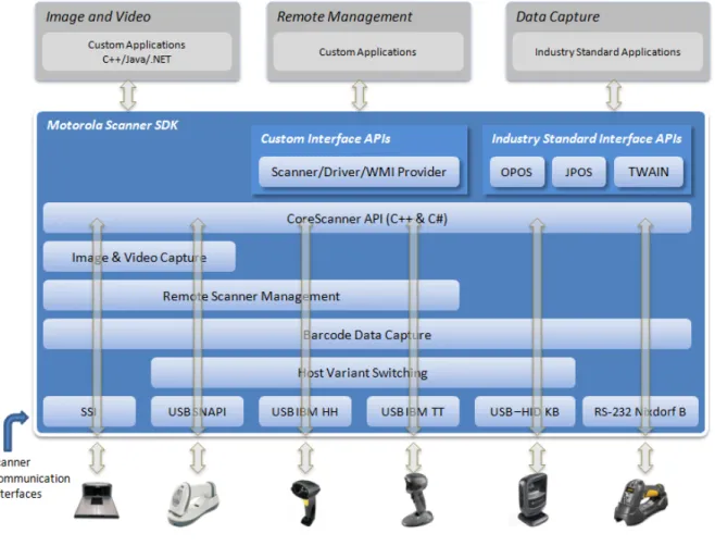
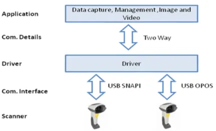
Figure 1-1 Software Developer Framework
The SDK can build an application with complete control of its scanner's capabilities.
•
Data, Barcode• Simulation HID Keyboard output • OPOS/JPOS output
•
Command and Control • LED and Beeper Control • Aim Control•
Imaging• Capture / Transfer of images • Capture / Transfer of Video
•
Remote Scanner Management• Asset Tracking
• Device Configuration (Get, Set and Store Scanner attributes) • Firmware Upgrade
• Scanner Communication Protocol Switching
• Service to Automate Configuration / Firmware Upgrade Process.
NOTE For a complete list of attribute (parameter) numbers and their definitions, download the Attribute Data Dictionary (p/n 72E-149786-xx) from http://MotorolaSolutions.com/WindowsSDK. Attributes include configuration parameters, monitored data and asset tracking information.
Quick Startup
Overview...1-1 Operating systems / System requirements ...2-2 Scanner model vs. Communication modes...1-6, 2-3 Block diagram of system ...1-5 SDK Components & Installation details...2-1, 2-3 Components and folder paths ...2-2, 2-8 Validate SDK installed properly...2-14, 4-7 OPOS / JPOS Drivers...2-1, 2-2, 2-6 WMI / Remote Scanner Management...2-2, 2-3, 2-6, 2-8 Test and sample utilities...4-2 Table of buttons and input fields...4-4 List of utility functionality ...4-2 Bar code Data Display ...A-14, A-13, 4-10, 4-10 One application connected to two scanners ...1-9 Simulated HID Keyboard Output ...1-6, 2-11, 4-4, 4-11 Discovery ...4-7 Querying asset information ...A-11, 4-7, 4-17, 4-19 Query and Set Parameters / Attributes
Query values...4-17, 4-19, 4-20 Set Value (Device Configuration)...3-17, 4-21 Programming an ADF rule ...4-20, 4-23 LED control ...4-16, 4-16, 4-24 Beeper control...A-9, 4-15, 4-15, 4-24 Enable / disable a symbology ...A-13, 4-22 Capturing an image...4-11 Capturing a video...4-11 Firmware Upgrade ...4-27, 4-28 Host Variant Switching ...4-26, 4-25 C++ sample application and source code ...2-8, 4-3, 5-1 C# sample application and source code ...2-8, 4-4, 5-1 Starter application using CoreScanner API ...A-1 API overview...3-1 Create com object ...5-1 Register for event...5-2, 4-7 Open ...A-6, 3-3, 5-2 Get scanner...A-7, 3-4, 4-8, 5-3 Execute command ...A-9, 4-17, 3-5, 5-3 List of Methods...3-17 Execute command asynchronously ...3-6, 5-3 Close ...3-6, 5-2 Attribute Data Dictionary (Index of Parameters)...4-1
FAQs
•
Can multiple scanners be connected to the CoreScanner Driver?• Yes, multiple scanners can be connected simultaneously to one host running the CoreScanner driver.
•
If two scanners are connected, can data be tracked by scanner ID?• Yes, if scanner X decodes a bar code 123, it returns to the application a data event consisting of 123
as the data label and the serial number as the scanner ID.
•
Can multiple applications be connected to the CoreScanner Driver?• Yes, multiple applications can be connected simultaneously on one host running the CoreScanner
driver. An application can register from a selection of event types (such as bar code, image, video or management). The application receives the event information plus the originating scanner ID.
•
Are the CoreScanner calls common across operating systems?• Yes. For example, the Open method's function signatures for C++ and Java are the same except for
the platform specific data and return types (highlighted in yellow below).
Motorola Scanner SDK Architecture
Figure 1-3 SDK Architecture
You can configure Motorola scanner devices to be operated in different host communication modes such as USB SNAPI, USB OPOS, USB HID Keyboard, USB IBM Table-top, SSI, and RS232 Nixdorf Mode B. Device feature support varies depending on communication mode but all modes support bar code scanning. Refer to the Product Reference Guide of a specific scanner for the bar codes to set its supported host communication modes.
Using the Motorola Scanner SDK, you can switch between supported host communication modes by calling the host variant switching command programmatically. This is useful when the device is in a less feature supportive mode and some advanced functionality is required but not supported by the current communication mode. The scanner can be switched to a feature rich mode and commands executed before switching the scanner back to the previous mode.
For example, you want to disable the UPC-A symbology but the device is in USB HID Keyboard mode. If the mode is supported by the scanner, you may switch to USB SNAPI or USB OPOS, set UPC-A to be disabled permanently and then switch the scanner back to USB HID Keyboard mode. See Table 1-1 on page 1-6 for
Table 1-1 illustrates scanner capabilities supported by each communication mode. Refer to the specifications
of a device for its ability to support of each communication mode.
Simulated HID Keyboard Output is a feature enabling scanners in USB SNAPI, USB IBM Table-top, USB OPOS, or SSI mode to emulate HID Keyboard keystrokes to a host system for scanned data labels. It sends the content of the scanned data label as HID Keyboard keystrokes thus emulating USB HID Keyboard scanner mode.
Table 1-1 Scanner Device Communication Modes Vs. Capabilities
Capabilities USB
SNAPI USB OPOS
USB HID Keyboard USB IBM Table-top RS232 Nixdorf B SSI
Data Supported Supported Supported Supported Supported Supported Host Variant Switching Supported Supported Supported Supported Not Available Not Available Management Supported Supported Not Available Supported Not Available Supported Image & Video Supported Not Available Not Available Not Available Not Available Supported
(Image Only) Simulated HID
Keyboard Output *
Supported Supported Not Applicable Supported Supported * Supported
Multiple Scanner Device Identification Methodology For Applications
The Motorola Scanner SDK supports multiple scanner devices to any application that runs on top of
CoreScanner APIs. Each scanner device is shown to the user application by a unique scanner identification number. The Scanner ID is a numeric value assigned to each connected device so there cannot be multiple scanner devices holding the same Scanner ID.
Asset tracking information like model number, serial number, current firmware version and date of manufacture are available if the scanner and its current host mode support the management feature.
For example, in some modes like USB HID Keyboard, you do not see asset tracking information but the same scanner device shows you such information when it is in USB OPOS or USB SNAPI mode.
The format of device asset tracking information can follow different naming conventions for device model, serial number or current firmware version. For example, the length of a serial number for DS6707 and DS9808 scanners can be different.
How Multiple Applications Access Multiple Scanners From Scanner SDK
The Motorola Scanner SDK supports multiple applications accessing multiple scanner devices connected to the host at the same time.
As described previously, a Scanner ID uniquely identifies a connected scanner device to all applications. A Scanner ID is consistent among all applications for one SDK instance. If the CoreScanner service or the host machine is restarted, a device may be assigned a different Scanner ID but it is unique and referenced by all applications.
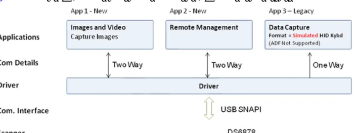
Three Applications Connected To One Scanner
Figure 1-4 illustrates how multiple applications communicate with multiple scanner devices.
Figure 1-4 Three Applications Connected To One Scanner
Implementation Details
•
Three applications are connected to one scanner.•
App 1 & App 2 support bi-directional (two way) communication with the scanner.•
Legacy App 3 supported by driver converting SNAPI data into HID format.Three Applications Connected To Two Scanners
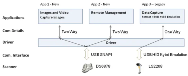
Figure 1-4 illustrates how multiple applications communicate with multiple scanner devices.
Figure 1-5 Three Applications Connected To Two Scanners
Implementation Details
•
Three applications are connected to two scanners.•
App 1 and App 2 support bi-directional (two way) communication with the DS6878.•
Legacy App 3 receives HID keyboard emulation data from the LS2208.Many-to-Many Application Device Usage
Figure 1-6 Many-to-Many Application Device Usage
Implementation Details
•
App 1 performs image capture with the DS6878.•
App 2 can remotely manage both the DS6878 and LS4208.•
App 3 receives OPOS data from both the DS6878 and LS4208.One Application Connected to Two Scanners
Figure 1-7 One Application Connected to Two Scanners
Implementation Details
•
One application can manage multiple scanners in multiple communication interfaces.•
The application can capture data, image and video, send management commands and receiveresponses from multiple scanners.
•
All responses from the scanners consist of the scanner device details (ScannerID, serial number, modelnumber, etc.) identifying the device that sent the response.
For example, a bar code event for a scanned label is shown below. The scanned data label arrives with a unique ScannerID and the scanner's model number and the serial number.
<?xml version="1.0" encoding="UTF-8"?> <outArgs> <scannerID>1</scannerID> <arg-xml> <scandata> <modelnumber>DS6707-SR20001ZZR </modelnumber> <serialnumber>7114000503308 </serialnumber> <GUID>9008A01BB72BA34BB519806B63701AAA</GUID> <datatype>11 </datatype> <datalabel>0x39 0x37 0x38 0x30 0x32 0x30 0x31 0x34</datalabel> <rawdata>0x39 0x37 0x38 0x30 0x32 0x30 0x31 0x34</rawdata> </scandata> </arg-xml> </outArgs>
CONFIGURATION
Overview
This chapter describes how to install Motorola Scanner SDK and its components on recommended platforms.
The SDK installation package includes support for:
•
Installing required components to enable any Motorola scanner to communicate with applications or toolsthat execute on top of the Motorola Scanner SDK.
•
Supporting documents.•
Test utilities.•
Sample applications and source projects.This section covers installation and configuration instructions.
For a list of the most commonly requested topics within this guide, see Quick Startup in the back of the guide. NOTE See System Requirements on page 2-2 for supported platforms.
NOTE Uninstall any previous Motorola, Symbol or 3rd party drivers or SDKs installed on your system which communicate with Motorola Scanner Devices before installing the Motorola Scanner SDK. This includes but is not limited to Motorola and Symbol supplied OPOS, JPOS and SNAPI drivers.
NOTE For a complete list of attribute (parameter) numbers and their definitions, download the Attribute Data Dictionary (p/n 72E-149786-xx) from http://MotorolaSolutions.com/WindowsSDK. Attributes include configuration parameters, monitored data and asset tracking information.
SDK Components
The SDK installation package includes following components.
•
Motorola Scanner SDK Core components and drivers (COM API, Imaging drivers)•
OPOS Drivers • Scanner OPOS • Scale OPOS•
JPOS Driers • Scanner JPOS • Scale JPOS•
Remote Management Components • Scanner WMI Provider• Driver WMI Provider
•
Web Link to latest Developer's Guide - Document(s)•
Test & Sample utilities with Source code packages• Motorola Scanner SDK Sample Application (C++)
• Motorola Scanner SDK Sample Application (Microsoft® C# .NET) • Scanner OPOS Test Utility
• Scale OPOS Test Utility
• JPOS Test Utility for Scanner and Scale
• Scanner WMI Provider Test Utility (Microsoft® C# .NET) • Driver WMI Provider Test Utility (Microsoft® C# .NET).
The SDK installation package installs its components to the following default location: C:\Program Files\Motorola Scanner\.
System Requirements
Supported Operating Systems
Recommended minimum hardware requirement: x86 PC for 32-bit SDK, or x64 PC for 64-bit SDK with 512Mb RAM.
Table 2-1 Supported Operating Systems
Motorola Scanner SDK Win32 Installation Package
Microsoft® Windows XP SP3 (32bit) Motorola_Scanner_SDK_(32bit)_v2.xx.xxxx.exe Microsoft® Windows 7 (32bit) Motorola_Scanner_SDK_(32bit)_v2.xx.xxxx.exe Microsoft® Windows 7 (64bit) Motorola_Scanner_SDK_(64bit)_v2.xx.xxxx.exe
Scanner Models Versus Communication Modes
For an up-to-date table listing scanner models and their supported communication modes refer to the Scanner SDK for Windows website at: www.motorolasolutions.com/windowssdk.
Installing the SDK
Download the relevant Motorola Scanner SDK setup program for the 32-bit or 64-bit operating system on your PC from http://MotorolaSolutions.com/WindowsSDK.
There are two options for installing the Motorola Scanner SDK on a system.
•
Typical installation - Loads all components in the installation package.•
Custom installation - Provides the ability to change the default selection of components.If you install components such as OPOS, JPOS or WMI provider (remote management), the installer automatically installs sample programs and test utilities related to those components.
To download the appropriate OPOS, JPOS and WMI Developer’s Guides go to: http://MotorolaSolutions.com/WindowsSDK.
Step-by-Step Installation Instructions
1. Execute the setup program. The installation process checks for CoreScanner drivers on the target
machine. If the driver package is not present or outdated, clicking Install adds updated drivers before
installing the Scanner SDK package.
2. Installation continues once the prerequisite drivers are installed on the machine.
Figure 2-2 Initial Window
3. Click Next on the Welcome screen.
4. Review the license agreement and click Yes to accept.
Figure 2-4 License Agreement
5. Select the Setup Type.
The user is prompted with two installation options:
• Complete - The installation package installs all components.
• Custom - The installation package gives the option to select which components are loaded during the
The user can select the destination folder by clicking Browse and selecting the drive and folder in which to
install the Motorola Scanner SDK. However, common components are placed in designated locations for consistency with other SDK users.
Figure 2-5 Setup Type
6. Select features. The user is prompted to select features to be installed from the available components list.
Figure 2-6 Select Features
7. Wait for the installation to complete.
Figure 2-7 Installation Progress
8. Installation complete.
Installed Components
Table 2-2 lists the components installed. Table 2-2 Motorola Scanner SDK Components
Component File Description Installation Path
Scanner Driver CoreScanner.exe Scanner Driver/COM
Server .\Common
Scanner Driver SNAPITrans.dll Transport Component .\Common Scanner Driver USBHIDKBTrans.dll Transport Component .\Common Scanner Driver NIXBTrans.dll Transport Component .\Common Scanner Driver IBMHIDTrans.dll Transport Component .\Common Scanner Driver SSITrans.dll Transport Component .\Common Scanner Driver IBMHIDTTTrans.dll Transport Comonent .\Common WMI Providers ScannerService.exe WMI Provider Services .\Common WMI Providers symbscnr.dll WMI Instance Providers .\Common WMI Providers ScannerWMITest.sln Scanner WMI Sample
Application \Scanner SDK\wmiprovider_scanner\Sample Applications\src
WMI Providers RSMDriverProviderService.exe WMI Provider Services .\Common WMI Providers RSMDriverProvider.dll WMI Instance Providers .\Common WMI Providers symbscnr.mof Managed Object Format
file for WMI and CIM .\Common WMI Providers RSMDriverProvider.mof Managed Object Format
file for WMI and CIM .\Common WMI Providers DriverWMITest.sln Driver WMI Sample
Application \Scanner SDK\wmiprovider_driver\Sample Applications\src
Configuration config.xml Scanner Driver
Configuration File .\Common Scanner Driver HIDKeyboardEmulator.exe HID Keyboard Emulator .\ Common\ SDK C++
Sample App source code
SampleApp_CPP.sln SDK C++ Sample Application and source projects
.\ Scanner SDK\ Scanner SDK\Sample Applications\src SDK C# Sample
App source code SampleApp_CSharp.sln SDK C++ Sample Application and source projects
.\ Scanner SDK\ Scanner SDK\Sample Applications\src OPOS OPOSScanner.ocx OPOS Scanner Control .\Scanner SDK\OPOS\Scale OPOS\Sample Applications\src
OPOS STIOPOS.dll OPOS Service Object .\Scanner SDK\OPOS\Scale OPOS\Sample Applications\src OPOS TestScan.sln OPOS Sample application
source project .\Scanner SDK\OPOS\Scale OPOS\Sample Applications\src OPOS OPOSScale.ocx OPOS Scale Control .\Scanner SDK\OPOS\Scale
OPOS\bin
OPOS ScaleOPOS.dll OPOS Scale Service .\Scanner SDK\OPOS\Scale OPOS\bin
OPOS MotorolaOPOSScaleSampleAp
p.sln OPOS Scale Sample Application source project .\Scanner SDK\OPOS\Scale OPOS\Sample Applications\src JPOS CSJPOS.dll JPOS JNI Layer for
CoreScanner API .\ Scanner SDK\JPOS\bin JPOS POStest JPOS Sample Application .\ Scanner SDK\JPOS\Sample
Applications\src
TWAIN twain.ds TWAIN driver data source %WinDir%\twain_32\Motorola (32-bit)
%WinDir%\twain_64\Motorola (64-bit)
TWAIN TWAIN_App_mfc32.exe TWAIN sample application .\ Scanner SDK\JPOS\Sample Applications\bin
TWAIN TWAIN_APP_MFC.sln TWAIN sample application source project
.\ Scanner SDK\JPOS\Sample Applications\src
Table 2-2 Motorola Scanner SDK Components (Continued)
Configuration
Serial Mode Settings
The Motorola Scanner SDK is capable of communicating with scanners connected to serial ports through Nixdorf Mode B, or SSI serial host mode. The SDK does not open any serial port without user consent to prevent other devices from being interfered with by Scanner SDK commands. Users can configure SDK usage of serial ports with entries in the < SERIAL_MODE_SETTINGS > section of the config.xml file located in %Program Files%\Motorola Scanner\Common.
Serial mode setting entries indicate the serial com port number (PORT ID), the baud rate (BAUD) and the
serial host mode (NAME) used to communicate with the attached scanner. The value of the name field can be NIXMODB, or SSI and the value of each of the three fields must be enclosed in quotation marks.
By default, the serial port settings in config.xml are commented out. To activate a serial mode setting, enter a line outside of the commented area, modify the settings appropriately, save the config.xml file and restart the Corescanner service.
Sample <SERIAL_MODE_SETTINGS> Definition in Config.xml
<SERIAL_MODE_SETTINGS><!-- Uncomment lines in this section to configure Serial Scanners <PORT ID='5' BAUD='9600' NAME='NIXMODB'/>
-->
<PORT ID='3' BAUD='9600' NAME='SSI'/> </ SERIAL_MODE_SETTINGS >
Simulated HID Keyboard Output
The Motorola Scanner SDK is capable of configuring a scanner to send simulated HID keyboard output (also known as HIDKB pump, or HIDKB emulation mode) while in USB SNAPI, USB IBM Hand-held, USB IBM Table-top, SSI, or RS-232 Nixdorf Mode B communication modes. This simulated HID keyboard output functionality can be configured by changing the XML elements in the <HID_KB_PUMP_SETTINGS> section of the config.xml file.
By default, the language locale of the simulated keyboard output is English. Only the English and French languages are currently supported.
Sample <HID_KB_PUMP_SETTINGS> definition in config.xml:
<HID_KB_PUMP_SETTINGS> <LOCALE>0</LOCALE> <!-- ENGLISH=0, FRENCH=1 --> <ENABLE>0</ENABLE> <!-- ENABLED=1, DISABLED=0 --> <FUNCTION_KEY_MAPPING>1</FUNCTION_KEY_MAPPING> <INTER_KEY_DELAY>0</INTER_KEY_DELAY> </HID_KB_PUMP_SETTINGS>Table 2-3 Config.xml File Elements
Tag Values Description
< ENABLE> 0, 1 0 - Disable (default) 1 - Enable
< LOCALE> 0, 1 0 - English (default) 1 - French
< FUNCTION_KEY_MAPPING> 0, 1 When - 0
VK_RETURN transmitted as VK_CONTROL + M VK_TAB transmitted as VK_CONTROL + I VK_BACK transmitted as VK_CONTROL + H When - 1
VK_RETURN transmitted as VK_RETURN VK_TAB transmitted as VK_TAB
VK_BACK transmitted as VK_BACK
Refer to your scanner's Product Reference Guide for further information on function key mapping.
< INTER_KEY_DELAY> 0, >0 Character transmission delay interval in milliseconds. The default value of zero transmits keystrokes as they are
decoded. If > 0, latency is introduced into key transmission so that any receiving application can adjust to the rate of
Notes
•
Refer to the specific scanner Product Reference Guide for supported serial port parameter settings.•
Simulated HID Keyboard Output settings can be temporarily changed by an application using theCoreScanner API commands KEYBOARD_EMULATOR_ENABLE and
KEYBOARD_EMULATOR_SET_LOCALE. To make permanent changes to these settings that remain persistent over a reboot of the host machine, the Config.xml file must be manually edited. Changes to Config.xml take effect only after the CoreScanner service is restarted.
•
When using the language locale with Simulated HID Keyboard Output, the user may need to change theinput language of the application receiving keyboard input to match the language specified in Config.xml.
•
Simulated HID Keyboard functionality becomes unavailable if you use Windows’ Switch Userfunctionality to switch the user on your PC. Manually restart the CoreScanner, RSM Driver Provider, and Symbol Scanner Management services, or reboot the host PC to ensure correct operation.
Simple Data Formatting (SDF)
SDF enables the formatting of scanned bar code data with prefix and suffix labels through the Corescanner driver. SDF is available while the scanner is in USB SNAPI, USB IBM Hand-held, USB IBM Table-top, SSI, or RS-232 Nixdorf Mode B communication mode1. Unlike Advanced Data Formatting (ADF), SDF does not permit modifying the scanned bar code data itself with any rule-based method. The prefix/suffix labels are composed of one or more ASCII characters (1-255). There can be one or more prefix/suffix labels, and they are defined in the config.xml file in the <SDF> section using the <SDFTAGDEF> tag. The SDF description is composed of a <SDFMETA> section, and a <SDFSELECT> section. The <SDFMETA> section defines the prefix/suffix labels used in SDF, and how they are combined in various ways to compose one or more SDF format definitions in the form of <SDFDEF> tags.
Sample <SDF> definition in config.xml:
<SDF> <SDFMETA> <SDFTAGDEF>SUFFIX1.SUFFIX2.PREFIX1.PREFIX2</SDFTAGDEF> <SUFFIX1>13.10</SUFFIX1> <SUFFIX2>35.36</SUFFIX2> <PREFIX1>37.38</PREFIX1> <PREFIX2>48.49.50</PREFIX2><SDFDEF SdfCode='0' SdfFormat='DATA'/>
<SDFDEF SdfCode='1' SdfFormat='DATA.SUFFIX1'/> <SDFDEF SdfCode='2' SdfFormat='DATA.SUFFIX2'/>
<SDFDEF SdfCode='3' SdfFormat='DATA.SUFFIX1.SUFFIX2'/> <SDFDEF SdfCode='4' SdfFormat='PREFIX2.DATA'/>
<SDFDEF SdfCode='5' SdfFormat='PREFIX2.DATA.SUFFIX1'/> <SDFDEF SdfCode='6' SdfFormat='PREFIX1.DATA.SUFFIX2'/>
<SDFDEF SdfCode='7' SdfFormat='PREFIX1.DATA.SUFFIX1.SUFFIX2'/> </SDFMETA>
<SDFSELECT>6</SDFSELECT> </SDF>
NOTE 1To add prefix/suffix formatting for a scanner in HID keyboard mode, use the programming bar codes in the scanner's Product Reference Guide.
In the XML sample above, four SDF prefix/suffix labels are defined as: SUFFIX1, SUFFIX2, PREFIX1, and PREFIX2. The values in these tags are delimited by a '.' character in the XML. Each of these labels is defined as shown below with the decimal ASCII character sequence that they represent:
SUFFIX1 = ascii(13), ascii(10) = CR, LF SUFFIX2 = ascii(35), ascii(36) = #, $ PREFIX1 = ascii(37), ascii(38) = %, &
PREFIX2 = ascii(48), ascii(49), ascii(50) = 0, 1, 2
Formats are also delimited by a '.' character in the XML. There can be one or more format definitions that use the above defined labels as follows:
<SDFDEF SdfCode='6' SdfFormat='PREFIX1.DATA.SUFFIX2' />
This format definition is identified by the keyword SdfCode and the format is represented by the keyword SdfFormat. Note that "DATA" is an intrinsic that means "Insert the Scanned Bar Code Here". The format definition to be executed is based on SdfCode and is specified in the <SDFSELECT> tag. The XML clause above would transmit the bar code data as:
Basic Installation Verification
You can perform a basic inspection on your system process list to verify a successful installation of the Motorola Scanner SDK.
The following instructions guide you through a simple check of the Scanner SDK's operation.
1. Right click on the Windows Task Bar and select Task Manager.
Figure 2-9 Task Bar Selection of Task Manager
2. Under the Processes tab, find the CoreScanner.exe in the Image Name list under.
Figure 2-10 CoreScanner.exe on Task Manager
3. The appearance of "CoreScanner.exe" in the Processes list indicates a successful installation.
NOTE This is simple verification of the operation of the Motorola Scanner SDK. See How to Verify Scanner SDK Functionality on page 4-7 for more advanced SDK testing.
Silent Unattended Installation of the Scanner SDK
An SDK component can be selectively installed using the SDK custom installation option. In conjunction with the custom install option, the SDK setup program supports command line switches to record custom
responses that can be used to create a silent install response file. These response files, ending in the extension .iss, may then be used to perform a silent installation of the scanner SDK on production PCs. When executed from a command prompt, the example below uses the –r and –f1 switches to record your responses to the setup prompts into a custom response file:
Motorola_Scanner_SDK_(xxbit)_v2.xx.xxxx.exe" -r -f1"c:\path\productionsetup.iss
The responses chosen using the command above are saved in the specified response file and can then be used as input to silently install the SDK on production PCs using the saved responses. The next example shows how the –s switch uses the response file created with the previous command to perform the install without user prompts:
Motorola_Scanner_SDK_(xxbit)_v2.xx.xxxx.exe" -s -f1"c:\path\productionsetup.iss
The –r switch option can also be used to record a custom response file for a silent removal of the SDK by running the command on a PC that has the SDK already installed.
NOTE There must be no space between the –f1 switch and first quotation mark for the response file.
IMPORTANT The Corescanner drivers are required for any SDK component so the Corescanner services are installed, and must be running to provide functionality.
Overview
The Motorola Scanner SDK provides an easy to use yet powerful and extendible set of API commands to interface with scanner devices. The API commands include:
•
Open•
GetScanners•
ExecCommand•
ExecCommandAsync•
Close.Once the SDKs Open and GetScanners commands are invoked and the list of connected scanners is
retrieved, all other methods execute through the ExecCommand and ExecCommandAsync commands. This is a user friendly approach, and easy to code in terms of day-to-day programming.
With the evolution of the SDK's capabilities, it is easier to increase the number of methods rather than increase the number of API commands. The benefit to the user is that, once you have the system up and running, a new method is just an additional operation to the existing code.
In addition to the commands above, the Motorola Scanner SDK supports seven types of events:
•
ImageEvent•
VideoEvent•
BarcodeEvent•
PNPEvent•
ScanRMDEvent•
CommandResponseEvent•
IOEvent•
BinaryDataEvent.See Appendix A, WRITE SIMPLE APPLICATIONS USING THE SCANNER SDK API for a starter example of
an application illustrating the Motorola Scanner SDK API. For a table listing the most commonly requested topics within this guide, see Quick Startup in the back of the guide.
NOTE For a complete list of attribute (parameter) numbers and their definitions, download the Attribute Data Dictionary (p/n 72E-149786-xx) from http://MotorolaSolutions.com/WindowsSDK. Attributes include configuration parameters, monitored data and asset tracking information.
Scanner ID
In the SDK context, scanner ID uniquely identifies a scanner device connected to the Corescanner driver, and is required to communicate programmatically with the device. Developers need to call the GetScanners method of the CoreScanner API in order to retrieve the scanner IDs of connected devices. For example, to switch on a scanner’s red LED, the scanner ID of that particular scanner must be obtained to provide that value in the <scannerID> element of inXML of the ExecCommand method call.
During each Corescanner driver instance, scanner IDs are sequentially assigned to each connected device. When the Corescanner driver is restarted, the array of connected scanners is reinitialized and previous scanner IDs may no longer be valid. In this case, the GetScanners method must be executed to obtain the new scanner IDs.
During a single Corescanner driver instance, an RSM1-supported scanner that is unplugged, and reconnected retaina its unique scanner ID. However, a non-RSM device is assigned a different scanner ID each time it is reconnected.
API Commands
Open
Opens an application instance from the user application or user library. This must be the first API command called before invoking any other API command from the user level application.
Syntax
Parameters
reserved - Reserved argument. Set to 0.
sfTypes - Selects the types of scanners requested for use with the API.
lengthOfTypes - Number of elements or the size of sfTypes array status - Return value for the command
Return Values
0 - Success.
Any other value - See Error and Status Codes on page 3-39.
C# C++
void Open(
int reserved,
System.Array sfTypes, short lengthOfTypes, out int status);
HRESULT STDMETHODCALLTYPE Open( /* [in] */ LONG reserved, /* [in] */ SAFEARRAY * sfTypes, /* [in] */ SHORT lengthOfTypes, /* [out] */ LONG *status) = 0;
Table 3-1 Values for sfTypes
Code Value Scanner Category
SCANNER_TYPES_ALL 1 All Scanners SCANNER_TYPES_SNAPI 2 SNAPI Scanners SCANNER_TYPES_SSI 3 SSI Scanners (RS232)
SCANNER_TYPES_IBMHID 6 IBM Hand Held Scanners (USB OPOS) SCANNER_TYPES_NIXMODB 7 Nixdorf Mode B scanners (RS232) SCANNER_TYPES_HIDKB 8 USB HID Keyboard emulation scanners SCANNER_TYPES_IBMTT 9 IBM Table Top Scanners
GetScanners
Gets a list of scanners of the requested types that are connected at any time. This command should be invoked after the Open command.
Syntax
Parameters
numberOfScanners - Number of connected scanners of requested type(s).
sfScannerIDList - Array of scannerIDs of the requested type(s). The size of the array is 255
(MAX_NUM_DEVICES).
outXML - XML string-scanner meta information. See Chapter 4, TEST UTILITIES & SOURCE CODE for
examples.
status - Return value for the command.
Return Values
0 - Success.
Any other value - See Error and Status Codes on page 3-39.
C# C++
void GetScanners(
out short numberOfScanners, System.Array sfScannerIDList, out string outXML,
out int status);
HRESULT STDMETHODCALLTYPE GetScanners( /* [out] */ SHORT *numberOfScanners,
/* [out][in] */ SAFEARRAY * sfScannerIDList, /* [out] */ BSTR *outXML,
ExecCommand
Provides synchronous execution of a method via an opcode.
Syntax
Parameters
opcode - Method to be executed. See Table 3-11 on page 3-17 for opcodes.
inXML - Relevant argument list for the opcode, structured into an XML string. outXML - XML string, scanner meta information.
status - Return value for the command.
Return Values
0 - Success.
Any other value - See Error and Status Codes on page 3-39.
C# C++
void ExecCommand( int opcode, ref string inXML, out string outXML, out int status);
HRESULT STDMETHODCALLTYPE ExecCommand( /* [in] */ LONG opcode,
/* [in] */ BSTR *inXML, /* [out] */ BSTR *outXML, /* [out] */ LONG *status) = 0;
ExecCommandAsync
Provides asynchronous execution of a method via an opcode. Any response data is retrieved as CommandResponseEvents. See CommandResponseEvent on page 3-14.
HRESULT STDMETHODCALLTYPE ExecCommandAsync( /* [in] */ LONG opcode,
/* [in] */ BSTR *inXML,
/* [out] */ LONG *status) = 0;
Syntax
Parameters
opcode - Method to be executed. See Table 3-11 on page 3-17 for opcodes.
inXML - Relevant argument list for the opcode, structured into an XML string. status - Return value for the command.
Return Values
0 - Success.
Any other value - See Error and Status Codes on page 3-39.
Close
Closes the application instance through the CoreScanner service.
Syntax
Parameters
reserved - Reserved argument. Set to 0. status - Return value for the command.
Return Values
0 - Success.
Any other value - See Error and Status Codes on page 3-39.
C# C++
void ExecCommandAsync( int opcode, ref string inXML, out int status);
HRESULT STDMETHODCALLTYPE ExecCommandAsync( /* [in] */ LONG opcode,
/* [in] */ BSTR *inXML,
/* [out] */ LONG *status) = 0;
C# C++
void Close(
int reserved, out int status);
HRESULT STDMETHODCALLTYPE Close( /* [in] */ LONG reserved, /* [out] */ LONG *status) = 0;
API Events
The user application must register for each event category separately to receive events for that category. Use the methods REGISTER_FOR_EVENTS and UNREGISTER_FOR_EVENTS for this purpose (see Table 3-11 on page 3-17).
ImageEvent
Triggered when an imaging scanner captures images in image mode. To receive ImageEvents, an application needs to execute the REGISTER_FOR_EVENTS method with the SUBSCRIBE_IMAGE event type.
Syntax
Parameters
eventType - Type of image event received (see Table 3-2).
size - Size of image data buffer.
imageFormat - Format of image. (See Table 3-3.)
sfimageData - Image data buffer.
pScannerData - Information in XML format about the scanner (ID, Model Number, Serial Number and GUID)
that triggered the image event.
<?xml version="1.0" encoding="UTF-8"?> <outArgs> <scannerID>1</scannerID> <arg-xml> <modelnumber>DS6707-SR20001ZZR</modelnumber> <serialnumber>7114000503322</serialnumber> <GUID>33C01F39EB23D949B5F3DBF643304FC4</GUID> </arg-xml> </outArgs> C# C++ void OnImageEvent( short eventType int size short imageFormat, ref object sfimageData, ref string pScannerData)
void OnImageEvent( SHORT eventType, LONG size, SHORT imageFormat, VARIANT *sfImageData, BSTR* pScannerData)
Table 3-2 Image Event Types
Event Type Value Description
IMAGE_COMPLETE 1 Triggered when complete image captured IMAGE_TRAN_STATUS 2 Triggered when image error or status
Table 3-3 Image Formats
Image Type Value
BMP_FILE_SELECTION 3 TIFF_FILE_SELECTION 4 JPEG_FILE_SELECTION 1
VideoEvent
Triggered when an imaging scanner captures video in video mode. To receive VideoEvents, an application needs to execute the REGISTER_FOR_EVENTS method with the SUBSCRIBE_VIDEO event type.
Syntax
Parameters
eventType - Type of video event received (see Table 3-4).
size - Size of video data buffer. sfvideoData - Video data buffer.
pScannerData - Reserved parameter: always returns an empty string.
BarcodeEvent
Triggered when a scanner captures bar codes. To receive BarcodeEvents, an application needs to execute the REGISTER_FOR_EVENTS method with the SUBSCRIBE_BARCODE event type.
Syntax
Parameters
eventType - Type of bar code event received (see Table 3-4).
C# C++
void OnVideoEvent( short eventType, int size,
ref object sfvideoData, ref string pScannerData)
void OnVideoEvent( SHORT eventType, LONG size,
VARIANT *sfvideoData, BSTR* pScannerData)
Table 3-4 Video Event Types
Event Type Value Description
VIDEO_FRAME_COMPLETE 1 Triggered when complete video frame is captured.
C# C++
void OnBarcodeEvent( short eventType, ref string pscanData)
void OnBarcodeEvent( SHORT eventType, BSTR pscanData )
Table 3-5 Bar Code Event Types
Event Type Value Description
pscanData - Bar code string that contains information about the scanner that triggered the bar code event
including data type, data label and raw data of the scanned bar code.
<?xml version="1.0" encoding="UTF-8"?> <outArgs> <scannerID>1</scannerID> <arg-xml> <scandata> <modelnumber>DS6707-SR20001ZZR</modelnumber> <serialnumber>7114000503322</serialnumber> <GUID>33C01F39EB23D949B5F3DBF643304FC4</GUID> <datatype>8</datatype> <datalabel>0x30 0x32 0x31 0x38 0x39 0x38 0x36 0x32</datalabel> <rawdata>0x30 0x32 0x31 0x38 0x39 0x38 0x36 0x32</rawdata> </scandata> </arg-xml> </outArgs>
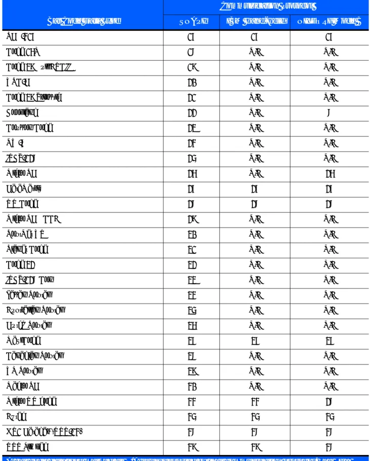
The value of the <datatype> in the XML above indicates the bar code type of the scanned bar code.
Table 3-6 lists the values received in IBM Hand-Held USB, SNAPI and Wincor-Nixdorf RS-232 Mode B
communication protocols for each supported bar code type.
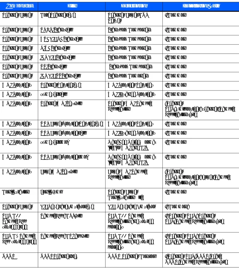
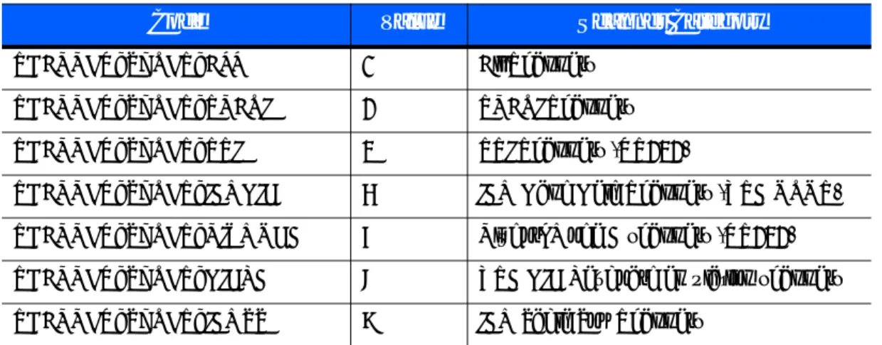
Table 3-6 Bar Code Data Types
Bar Code Data Type
Communication Protocol
SNAPI IBM Hand-Held NIXDORF Mode B
Code 39 1 1 1 Codabar 2 2 2 Code 128 3 3 3 Discrete (Standard) 2 of 5 4 4 4 IATA 5 N/A 4 Interleaved 2 of 5 6 6 6 Code 93 7 7 7 UPC-A 8 8 8 UPC-E0 9 9 9 EAN-8 10 10 10 EAN-13 11 11 8
Code 11 12 N/A N/A
Code 49 13 13 N/A
MSI 14 N/A 14
EAN-128 15 15 15
UPC-E1 16 N/A N/A
A bar code data type marked as N/A is unsupported by that communication protocol. The SDK typically returns a value of 0 for these bar code data types. However, in some cases the SDK may identify these symbologies as a related data type. For example, UPC-A + 2 Supplemental is not a supported symbology in Nixdorf Mode B but the SDK identifies it as UPC-A.
PDF-417 17 17 17
Code 16K 18 N/A N/A
Code 39 Full ASCII 19 N/A N/A
UPC-D 20 N/A N/A
Code 39 Trioptic 21 N/A N/A
Bookland 22 N/A 8
Coupon Code 23 N/A N/A
NW-7 24 N/A N/A
ISBT-128 25 N/A N/A
Micro PDF 26 N/A 26
DataMatrix 27 27 27
QR Code 28 28 28
Micro PDF CCA 29 N/A N/A
PostNet US 30 N/A N/A
Planet Code 31 N/A N/A
Code 32 32 N/A N/A
ISBT-128 Con 33 N/A N/A
Japan Postal 34 N/A N/A
Australian Postal 35 N/A N/A
Dutch Postal 36 N/A N/A
MaxiCode 37 37 37
Canadian Postal 38 N/A N/A
UK Postal 39 N/A N/A
Macro PDF 40 N/A N/A
Micro QR code 44 44 28
Aztec 45 45 45
GS1 Databar (RSS-14) 48 48 48
RSS Limited 49 49 48
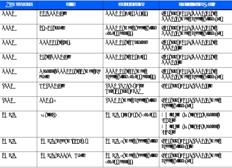
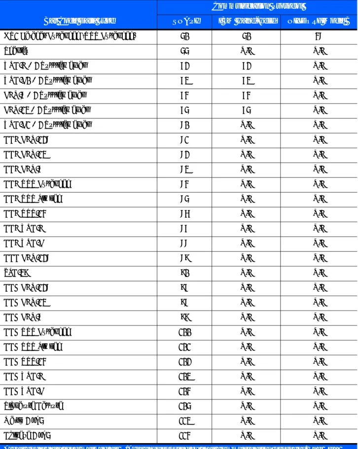
Table 3-6 Bar Code Data Types (Continued)
Bar Code Data Type
Communication Protocol
SNAPI IBM Hand-Held NIXDORF Mode B
A bar code data type marked as N/A is unsupported by that communication protocol. The SDK typically returns a value of 0 for these bar code data types. However, in some cases the SDK may identify these symbologies as a related data type. For example, UPC-A + 2 Supplemental is not a supported symbology in Nixdorf Mode B but the SDK identifies it as UPC-A.
GS1 Databar Expanded (RSS Expanded) 50 50 48
Scanlet 55 N/A N/A
UPC-A + 2 Supplemental 72 72 N/A
UPC-E0 + 2 Supplemental 73 73 N/A
EAN-8 + 2 Supplemental 74 74 N/A
EAN-13 + 2 Supplemental 75 75 N/A
UPC-E1 + 2 Supplemental 80 N/A N/A
CCA EAN-128 81 N/A N/A
CCA EAN-13 82 N/A N/A
CCA EAN-8 83 N/A N/A
CCA RSS Expanded 84 N/A N/A
CCA RSS Limited 85 N/A N/A
CCA RSS-14 86 N/A N/A
CCA UPC-A 87 N/A N/A
CCA UPC-E 88 N/A N/A
CCC EAN-128 89 N/A N/A
TLC-39 90 N/A N/A
CCB EAN-128 97 N/A N/A
CCB EAN-13 98 N/A N/A
CCB EAN-8 99 N/A N/A
CCB RSS Expanded 100 N/A N/A
CCB RSS Limited 101 N/A N/A
CCB RSS-14 102 N/A N/A
CCB UPC-A 103 N/A N/A
CCB UPC-E 104 N/A N/A
Signature Capture 105 N/A N/A
Matrix 2 of 5 113 N/A N/A
Chinese 2 of 5 114 N/A N/A
Table 3-6 Bar Code Data Types (Continued)
Bar Code Data Type
Communication Protocol
SNAPI IBM Hand-Held NIXDORF Mode B
A bar code data type marked as N/A is unsupported by that communication protocol. The SDK typically returns a value of 0 for these bar code data types. However, in some cases the SDK may identify these symbologies as a related data type. For example, UPC-A + 2 Supplemental is not a supported symbology in Nixdorf Mode B but the SDK identifies it as UPC-A.
PNPEvent
Triggered when a scanner of a requested type attaches to the system or detaches from the system. The pairing of a Bluetooth scanner to a cradle does not trigger a PnP event. To receive information about a newly paired device, the GetScanners command must be called again. To receive PnPEvents, an application needs to execute the REGISTER_FOR_EVENTS method with the SUBSCRIBE_PNP event type.
Syntax
Parameters
eventType - Type of PnP event received (see Table 3-7).
ppnpData - PnP information string containing the asset tracking information of the attached or detached
device.
UPC-A + 5 Supplemental 136 136 N/A
UPC-E0 + 5 Supplemental 137 137 N/A
EAN-8 + 5 Supplemental 138 138 N/A
EAN-13 + 5 Supplemental 139 139 N/A
UPC-E1 + 5 Supplemental 144 N/A N/A
Macro Micro PDF 154 N/A N/A
Table 3-6 Bar Code Data Types (Continued)
Bar Code Data Type
Communication Protocol
SNAPI IBM Hand-Held NIXDORF Mode B
A bar code data type marked as N/A is unsupported by that communication protocol. The SDK typically returns a value of 0 for these bar code data types. However, in some cases the SDK may identify these symbologies as a related data type. For example, UPC-A + 2 Supplemental is not a supported symbology in Nixdorf Mode B but the SDK identifies it as UPC-A.
C# C++
void OnPNPEvent( short eventType, ref string ppnpData)
void OnPNPEvent ( SHORT eventType, BSTR ppnpData)
Table 3-7 PnP Event Types
Event Type Value Description
SCANNER_ATTACHED 0 Triggered when a Motorola Scanner is attached. SCANNER_DETACHED 1 Triggered when a Motorola Scanner is detached.
Samples
Sample ppnpData XML for attachment of a direct scanner. <?xml version="1.0" encoding="UTF-8"?> <outArgs>
<arg-xml>
<scanners>
<scanner type="SNAPI">
<scannerID>1</scannerID>
<modelnumber>DS9808-SR00007C1WR</modelnumber>
<serialnumber>1026300507698 </serialnumber>
<GUID>77E48FC31C75444B90BE318FECFAE867</GUID>
</scanner>
</scanners>
<status>1</status>
</arg-xml> </outArgs>
Sample ppnpData XML for attachment of a cascaded scanner. This XML can be received as a PnP event after a GetScanners command, if there are devices newly paired to a Bluetooth cradle.
<?xml version="1.0" encoding="UTF-8"?> <outArgs>
<arg-xml>
<scanners>
<scanner type="USBIBMHID">
<scannerID>1</scannerID>
<modelnumber>CR0078-SC10007WR </modelnumber>
<serialnumber>1020800512980 </serialnumber>
<GUID>3665579766A9514DAAF523D35E051674</GUID>
<pnp>0</pnp>
<scanner type="USBIBMHID">
<scannerID>2</scannerID>
<modelnumber>DS6878-SR20007WR </modelnumber>
<serialnumber>M1M87R38Y </serialnumber>
<GUID></GUID> <pnp>1</pnp> </scanner> </scanner> </scanners> <status>1</status> </arg-xml> </outArgs> Information about Bluetooth Cradle Information about Bluetooth Scanner
ScanRMDEvent
Receives RMD Events when updating firmware of the scanner. To receive RMD Events, an application needs to execute the REGISTER_FOR_EVENTS method with the SUBSCRIBE_RMD event type.
Syntax
Parameters
eventType - Type of the RMD event received (see Table 3-8).
prmdData - ScanRMD information string containing the data of event. (See Firmware Upgrade Scenarios on page 4-27 for more details on this string.)
CommandResponseEvent
Received after an asynchronous command execution (ExecCommandAsync). To receive
CommandResponseEvents, an application needs to execute the REGISTER_FOR_EVENTS method with the SUBSCRIBE_OTHER event type.
Syntax
Parameters
status - Status of the executed command. (See Error/Status Codes on page 3-39.)
prspData - CommandResponse information string that contains the outXML of the executed command.
C# C++
void OnScanRMDEvent( short eventType, ref string prmdData)
void OnScanRMDEvent ( SHORT eventType, BSTR prmdData )
Table 3-8 RMD Event Types
Event Type Value Description
SCANNER_UF_SESS_START 11 Triggered when flash download session starts. SCANNER_UF_DL_START 12 Triggered when component download starts. SCANNER_UF_DL_PROGRESS 13 Triggered when block(s) of flash completed. SCANNER_UF_DL_END 14 Triggered when component download ends. SCANNER_UF_SESS_END 15 Triggered when flash download session ends. SCANNER_UF_STATUS 16 Triggered when update error or status.
C# C++
void OnCommandResponseEvent(short status, ref string prspData)
void OnScanRMDEvent ( SHORT status, BSTR prspData)
IOEvent
Received when an exclusively claimed device is accessed by another client application. To receive IOEvents, an application needs to execute the REGISTER_FOR_EVENTS method with the SUBSCRIBE_OTHER event type. Standard practice is that an application handles these IO Events once it has claimed a scanner. While that application has the scanner claimed, other applications get STATUS_LOCKED when they try to execute commands directed toward the claimed scanner.
Syntax
Parameters
type - Reserved parameter. data - Reserved parameter.
ScannerNotificationEvent
Received when a SNAPI scanner changes its operational mode. To receive ScannerNotificationEvents, an application needs to execute the REGISTER_FOR_EVENTS method with the SUBSCRIBE_OTHER event type.
Syntax
Parameters
notificationType - Type of the notification event received (see Table 3-9).
pScannerData - Information about the scanner (ID, Model Number, Serial Number and GUID) that triggered
the notification event.
C# C++ void OnIOEvent( short type, byte data) void OnIOEvent( short type, BYTE data) C# C++ void OnScannerNotification ( short notificationType, ref string pScannerData)
void OnScannerNotification ( short notificationType, BSTR pScannerData)
Table 3-9 Notification Event Types
Notification Type Value Description
DECODE_MODE 1 Triggered when a scanner changes its operation mode to decode.
SNAPSHOT_MODE 2 Triggered when a scanner changes its operation mode to image mode.
VIDEO_MODE 3 Triggered when a scanner changes its operation mode to video mode.