Fire Protection and Life Safety Analysis
of a
Chicago Hotel
Tom Hampton
June 10, 2020
2
Statement of Disclaimer
This project report is a result of a class assignment; it has been graded and accepted as fulfillment of the course requirements. Acceptance of this report in fulfillment of the course requirements does not imply technical accuracy or reliability. Any use of information in this report is done at the risk of the user. These risks may include, but may not be limited to, catastrophic failure of the device or infringement of patent or copyright laws. California Polytechnic State University at San Luis Obispo and its staff cannot be held liable for any use or misuse of the project.
3
Contents
Statement of Disclaimer ... 2
Executive Summary ... 6
1. Introduction and Building Description ... 7
1.1 Applicable Codes ... 10
2. Life Safety Analysis ... 11
2.1 Occupancy Classifications ... 11
2.2 Occupant Load ... 11
2.3 Means of Egress Analysis ... 12
2.3.1 Exit Capacity ... 12
2.3.2 Arrangement & Number of Exits... 14
2.3.3 Horizontal Exits ... 15
2.3.4 Exit Signs ... 15
2.3.1 Hotel Evacuation Diagrams ... 15
2.4 Fire Resistance Ratings... 16
2.5 Smokeproof Enclosures and Elevator Hoistway Protection ... 18
2.6 Interior Finish ... 19
2.7 Estimated Evacuation Time ... 20
2.7.1 Characteristics of Occupants... 20
2.7.2 Hand Calculations of Evacuation Time ... 21
3. Suppression System Analysis ... 24
3.1 Automatic Sprinkler Systems ... 24
3.1.1 Classification of Sprinkler System Occupancy Hazard Groups ... 24
3.1.2 System Design Criteria ... 25
3.2 Water Supply ... 25
3.3 Fire Pump ... 25
3.4 Fire Department Connections ... 25
3.5 Hydraulic Calculation ... 26
3.6 Inspection, Testing & Maintenance ... 28
4. Fire Alarm and Detection ... 30
4.1 Operating Characteristics of the Fire Alarm System ... 30
4.2 Fire Alarm Control Panel and Fire Command Center... 30
4
4.4 Fire Scenario and Expected Response ... 33
4.5 Alarm, Supervisory, and Trouble Signals... 34
4.6 Notification Devices ... 35
4.7 Secondary Power Supply Requirements ... 41
4.8 Required Records and Documentation ... 43
4.9 Inspection, Testing and Maintenance Requirements ... 44
5. Structural Fire Protection ... 46
5.1 Code Required Fire Resistance Ratings ... 46
5.2 Construction Materials ... 48
5.3 Impact of Design Fire Scenarios on Structural Integrity ... 48
5.3.1 Design Fire Analyses ... 49
5.3.2 Structural Analysis Under Fire Conditions ... 56
5.3.3 Protective Design for Structural Members ... 60
6. Fire Safety Management Plan ... 61
6.1 Fire Safety Plan... 61
6.2 General Fire Safety Requirements During Occupancy ... 62
6.3 Emergency Procedures ... 63
6.4 Emergency Drills ... 64
6.5 Staff Training ... 64
7. Performance Based Evaluation ... 65
7.1 Fire Modeling ... 65
7.1.1 Fire Modeling Software ... 65
7.1.2 Assumptions Related to FDS Fire Simulations ... 66
7.2 Egress Modeling ... 67
7.2.1 Egress Modeling Software ... 67
7.3 Tenability Criteria ... 67
7.4 Design Fire Scenario 1 – Basement Parking Garage Car Fire ... 69
7.4.1 Fuel Load and Heat Release Rate of Design Fire 1 ... 69
7.4.2 Sprinkler System Impact on Design Fire 1 ... 71
7.4.3 Products of Combustion of Design Fire 1... 75
7.4.4 Design Fire Scenario 1 - Fire and Egress Modeling ... 76
7.5 Design Fire Scenario 2 – Level 7 Restaurant/Bar Fire ... 86
5
7.5.2 Sprinkler System Impact on Design Fire 2 ... 88
7.5.3 Products of Combustion of Design Fire 2... 90
7.5.4 Design Fire Scenario 2 - Fire and Egress Modeling ... 90
8. Conclusion ... 100
8.1 Recommendations ... 100
References ... 102
Appendix A: Life Safety Drawings ... 103
Appendix B: Exit Sign Drawings ... 104
Appendix C: Occupant Load Calculation ... 105
Appendix D: Suppression System Occupancy Classification, Standpipe/Riser Location & Hydraulically Remote Design Area Sprinkler Layout Drawings ... 113
Appendix E: Hydraulically Remote Design Area Node Layouts ... 114
Appendix F: Mechanical Penthouse Hydraulic Calculation ... 115
Appendix G: Tenant Space Hydraulic Calculation ... 116
Appendix H: Hydraulic Supply and Demand Curves for Remote Areas ... 117
Appendix I: Suppression System Inspection, Testing & Maintenance Requirements ... 118
Appendix J: Fire Alarm Drawings ... 124
Appendix K: Fire Alarm Record of Completion ... 125
Appendix L: Heat Transfer Analysis Boundary Conditions and Equations ... 126
Appendix M: Design Fire Scenario Structural Analysis Calculation ... 127
6
Executive Summary
The following report contains an analysis of the life safety and fire protection features of a Chicago Hotel. The report is intended to meet the requirements for the Culminating Experience of the Cal Poly Master of Science Fire Protection Engineering Program.
The Chicago Hotel building chosen for the analysis is a mixed-use 7-story hotel. On the 1st, 2nd, and 7th
floors of the building are spaces for mercantile and restaurant tenants as well as other spaces necessary for the operation of the building such as back of house space for the hotel, storage, employee locker rooms, hotel and retail lobbies, etc. The 3rd to 6th floors are dedicated to hotel rooms with some
business space on the 3rd floor for the hotel managers. There is a parking garage in the basement. The
building is fully sprinklered throughout. The building is of Type I-A noncombustible construction. This report contains analysis of the prescriptive code requirements and provided fire protection and life safety features of the Chicago Hotel. Topics covered include means of egress, suppression system, fire alarm and detection and structural fire protection.
Applicable codes, regulations and standards include: • International Building Code (IBC), 2015 Edition • Life Safety Code, NFPA 101, 2015 Edition
o Used for technical means of egress requirements. The more conservative requirement between NFPA 101 and the IBC is chosen.
• International Fire Code (IFC), 2015 Edition
It should be noted that the design phase drawings that are included in various appendices of this report were developed by professional architects and engineers according to the Chicago Building Code. As this report is an academic exercise, this report evaluates the International Code Council model building and fire codes and the National Fire Protection Associations codes and standards which are adopted on a much more widespread basis than the Chicago Building Code. The building is largely in compliance with the International Building Code and NFPA standards; two deficiencies are noted in the report and conclusion related to exit capacity on Level 7 and visual notification appliance spacing.
This report also contains a performance-based evaluation. The performance-based evaluation included in Section 7 of the report evaluates two design fire scenarios to determine the capability of occupants to safely evacuate in the event of the fire scenario. The results can be summarized as follows:
• Design Fire Scenario 1: The vehicle fire in the underground enclosed parking garage showed that safe evacuation is possible for occupants who are initially located in the open parking garage area as they are able to sense the fire (sight, smell, etc.) and begin to exit prior the activation of the fire alarm notification appliances. Occupants who are located in enclosed rooms and dependent on the fire alarm system experience untenable visibility conditions during their egress. Ventilation openings or a smoke exhaust system are recommended to be
considered to limit the reduction in visibility loss in the event of a fire in the basement.
7
1.
Introduction and Building Description
This report contains a fire protection and life safety analysis for a Chicago Hotel. The hotel was evaluated against model building and life safety codes. The report includes analysis and consideration of the following topics:
• Means of egress and life safety • Suppression system
• Fire alarm and detection • Structural fire protection • Fire safety management plan
The report also includes a performance-based evaluation that considers two design fire scenarios using computational fluid dynamics modeling. The purpose of the performance-based evaluation is to evaluate if occupants can safely egress from the building under assumed, theoretical design fire scenarios.
The hotel that is the focus of this report is in Chicago, Illinois and is shown below in Figure 1. The Chicago Hotel is a mixed-use 7-story building with a basement parking garage.
Figure 1. Chicago Hotel
There is an underground, enclosed parking garage in the basement with incidental mechanical, electrical and plumbing (MEP) rooms and storage space. The 1st and 2nd floors of the building contain spaces for
mercantile and restaurant tenants as well as other spaces necessary for the operation of the building including back of house hotel spaces, storage, employee locker rooms, hotel and retail lobbies, etc. Each mercantile and restaurant tenant has direct access doors to the street level so that customers may enter from the sidewalk. The 1st and 2nd floor are connected via an open stairway in the center of the
building that connects the main entrance to the hotel lobby on the 2nd floor. The 3rd to 6th floors are
dedicated to hotel rooms with small spaces for an exercise room and business space on the 3rd floor.
Half of the 7th floor is provided for a restaurant and bar tenant with a large outdoor terrace for customer
8 Two elevator bays serve the building, one located in the center and one on the south end of the
building. There are four stairways. The parking garage is served by two exit stairs, the 2nd level is served
by four exit stairs, and the 3rd through 7th levels are served by three exit stairs.
Screenshots of architectural floor plans for the building are provided in Figures 2 through 7 below. The building is provided with an automatic sprinkler system throughout and a fire pump that is located in the basement. A fire alarm system and emergency voice alarm communication (EVAC) system is provided that allows for voice messages to be broadcast.
The building is of Type I-A noncombustible construction and is constructed primarily of reinforced concrete. The hotel is classified as a high-rise building which have specific prescriptive requirements. Life Safety Drawings are included in Appendix A and can be referenced for details on the layout and use of each floor. Table 1, below, includes basic information about each floor of the building.
Table 1. Chicago Hotel Building Overview
Floor Function Area (sqft) Height Basement Parking garage, storage/mechanical 43,120 -11’0” (below
grade) 1st Hotel entrance, restaurant and mercantile tenants,
storage/mechanical
37,481 0’ 0” 2nd Hotel lobby and reception, restaurant and mercantile
tenants, storage/mechanical
33,814 16’ 8” 3rd Hotel rooms, exercise room, office space,
storage/mechanical
27,507 34’ 2” 4th Hotel rooms, storage/mechanical 26,010 44’ 2”
5th Hotel rooms, storage/mechanical 26,010 54’ 2”
6th Hotel rooms, storage/mechanical 26,010 64’ 2”
7th Restaurant and bar space, storage/mechanical 18,040 76’ 2”
9 Figure 3. 1st Floor
Figure 4. 2nd Floor
10 Figure 6. 4th-6th Floor
Figure 7. 7th Floor
1.1
Applicable Codes
It should be noted that the design phase drawings that are included in various appendices of this report were developed by professional architects and engineers according to the Chicago Building Code. As this report is an academic exercise, this report evaluates the International Code Council model building and fire codes and the National Fire Protection Associations codes and standards which are adopted on a much more widespread basis than the Chicago Building Code.
The following codes were used in the development of this report: • International Building Code (IBC), 2015 Edition
• NFPA 101, Life Safety Code, 2015 Edition
o Used for technical means of egress requirements. The more conservative requirement between NFPA 101 and the IBC is chosen.
• International Fire Code (IFC), 2015 Edition
• NFPA 13, Installation of Sprinkler Systems, 2016 Edition • NFPA 72, National Fire Alarm and Signaling Code, 2013 Edition • NFPA 70, National Electric Code, 2014 Edition
• NFPA 25, Standard for the Inspection, Testing, and Maintenance of Water-Based Fire Protection
11
2.
Life Safety Analysis
A life safety analysis has been performed using the 2015 editions of the NFPA 101, Life Safety Code and the International Building Code. Comparison on egress topics addressed by both codes has been made and the more restrictive requirement is selected for use in the building. The analysis includes an occupant load calculation, means of egress analysis, evaluation of various fire resistance rating
requirements related to separation and compartmentation of the building, interior finish requirements and an estimated evacuation time based on hand-calculations.
2.1
Occupancy Classifications
In accordance with IBC Chapter 3, areas within the building are assigned an occupancy classification based on the anticipated type of use and have specific prescriptive requirements associated with the classification. Multiple occupancies within the same building are considered to be mixed-use and must comply with IBC Section 508. Per IBC Section 508, the hotel will be a separated mixed-use building. Separated mixed-use buildings are required to provide occupancy separations (fire resistant
construction) between different occupancies.
Table 2 identifies the occupancy classifications per IBC Chapter 3 that are located on each floor of the building.
Table 2. Occupancy Classifications per Floor Floor Occupancy Classification
(IBC Ch. 3)
Floor Functions
Basement S-1, S-2 Parking garage, storage/mechanical
1st M, S-1, B, A-2 Hotel entrance, restaurant and mercantile tenants, storage/mechanical
2nd M, S-1, B, A-2 Hotel lobby and reception, restaurant and mercantile tenants, storage/mechanical
3rd R-1, B Hotel rooms, exercise room, office space, storage/mechanical
4th R-1 Hotel rooms, storage/mechanical
5th R-1 Hotel rooms, storage/mechanical
6th R-1 Hotel rooms, storage/mechanical
7th A-2, B, S-1 Restaurant and bar space, storage/mechanical
2.2
Occupant Load
The occupant load of the building was calculated according to IBC Table 1004.1.2 and NFPA 101 Table 7.3.1.2 which specify occupant loading factors. A comparison was made between the two tables and the more conservative occupant loading factor is used. The occupant loads of each individual floor and the overall occupant load of the building is summarized in Table 3. Detailed tables for each floor of the building showing the room name, occupancy classification, occupant loading factor, area of the space, and occupant load are provided in Appendix C. A color-coded legend for occupancy classification is provided on the life safety drawings provided in Appendix A.
12 Floor Occupant Load
Basement 185 1st 600
2nd 560
3rd 139
4th 105
5th 105
6th 105
7th 542
Total: 2340
2.3
Means of Egress Analysis
2.3.1
Exit Capacity
Exit capacity factors are taken from NFPA 101 Table 7.3.3.1 and IBC Table 1005.3 accounting for a fully sprinklered building. The relevant capacity factors are shown in Table 4; note that the NFPA 101 exit capacity factors are more conservative than the IBC factors as NFPA 101 does not allow for an increase in exit capacity for providing an emergency voice alarm communication system. Exit capacities were calculated for each floor and are shown in Tables 5 through 9 below. All exit capacities are greater than the occupant load, except for Level 7 which exceeds the exit capacity by one occupant only.
NFPA 101 7.3.3.2 references an equation which allows for increased exit capacity above the 0.3 inch width per person capacity factor, to be granted for exit stairs that are greater than 44 inches in width. NFPA 101 equation 7.3.3.2 is as follows:
C = 146.7 +W𝑛− 44 0.218 Where
C = capacity, in persons, rounded to the nearest integer W𝑛= nominal width of the stair
Table 4. Capacity Factors of Egress Components
Exit IBC Table 1005.3 NFPA 101 Table 7.3.3.1 Stairs 0.2” per person (w/emergency
voice alarm communication system)
0.3” per person
Level Component (Door, corridor, horizontal exits, etc.)
0.15” per person (w/emergency voice alarm communication system)
0.2” per person
Table 5. Basement Exit Capacity
Exit Exit Capacity Clear Width (In.) Capacity Factor
Stair 01 (limited by door) 170 56 0.2” per person
Stair 04 (limited by door) 170 56 0.2” per person
13 Table 6. First Floor Exit Capacity
Exit Exit Capacity Clear Width (In.) Capacity Factor Stair 01 (limited by door) 170 34 0.2" per person Stair 02 (limited by door) 170 34 0.2" per person Stair 03 (limited by door) 170 34 0.2" per person Stair 04 (limited by door) 170 34 0.2" per person
Ext. Door 1 170 34 0.2" per person
Ext. Door 2 360 72 0.2" per person
Ext. Door 3 360 72 0.2" per person
Ext. Door 4 360 72 0.2" per person
Ext. Door 5 360 72 0.2" per person
Ext. Door 6 360 72 0.2" per person
Ext. Door 7 360 72 0.2" per person
Ext. Door 8 360 72 0.2" per person
Ext. Door 9 360 72 0.2" per person
Ext. Door 10 360 72 0.2" per person
Ext. Door 11 360 72 0.2" per person
Ext. Door 12 170 34 0.2" per person
Total: 4620
Table 7. Second Floor Exit Capacity
Exit Exit Capacity Clear Width (In.) Capacity Factor Stair 01 (limited by stairs) 201 56 NFPA 101 7.3.3.2
Stair 02 (limited by door) 170 34 0.2" per person Stair 03 (limited by stairs) 201 56 NFPA 101 7.3.3.2
Stair 04 (limited by door) 170 34 0.2" per person
Total: 742
Table 8. Third, Fourth, Fifth, and Sixth Floor Exit Capacities
Exit Exit Capacity Clear Width (In.) Capacity Factor Stair 01 (limited by door) 170 34 0.2" per person Stair 02 (limited by door) 170 34 0.2" per person Stair 03 (limited by door) 170 34 0.2" per person
Total: 510
Table 9. Seventh Floor Exit Capacity
Exit Exit Capacity Clear Width (In.) Capacity Factor Stair 01 (limited by door) 170 34 0.2" per person Stair 02 (limited by stairs) 201 56 NFPA 101 7.3.3.2
Stair 03 (limited by door) 170 34 0.2" per person
14 2.3.1.1 Recommendation to Increase Exit Capacity on Level 7
The occupant load of level 7 exceeds the exit capacity by one and is not in compliance with NFPA 101. To fix this noncompliance, it is recommended that the doors for Stair 01 and Stair 03 as shown in Table 9, above, be increased in width. This would permit an additional 31 units of exit capacity per stair to be provided as the stairway egress system is limited by the width of the doors entering into the stairway (not the width of the stairs).
2.3.2
Arrangement & Number of Exits
Exit access travel distance, common path of travel, and dead-end distances have been measured on the life safety drawings provided in Appendix A and meet the minimum code requirements. The distances permitted by the IBC and NFPA 101 are shown in Table 10.
According to IBC 1006.2 and NFPA 101 7.4.1.2, 3 exits are required for occupant loads of 500-1,000 and 4 exits for occupant loads greater than 1,000. The number of exits provided on each floor of the hotel is adequate.
Table 10. Travel Distance, Dead-End, and Common Path of Travel Distance Limits Maximum Travel Distance IBC Table 10017.2
Sprinklered
NFPA 101 Table A.7.6 Sprinklered
Assembly 250 ft 250 ft
Business 300 ft 300 ft
Residential (Hotels) 250 ft
325 ft
28.2.6.2 Within a guest room or guest suite to corridor door: 125 ft 28.2.6.3.3.1 Corridor door of guest room
or guest suite to exit: 200 ft
Parking (Enclosed) 400 ft 200 ft
Mercantile 250 ft 250 ft
Storage (ordinary hazard) 250 ft (S-1), 400 ft (S-2) 400 ft Maximum Dead-end
Corridor IBC 1020.4
NFPA 101 Table A.7.6 Sprinklered
Assembly 20 ft 20 ft
Business 50 ft 50 ft
Residential (Hotels) 50 ft 50 ft
Parking (Enclosed) 50 ft 50 ft
Mercantile 50 ft 50 ft
Storage (ordinary hazard) 50 ft 100 ft
Maximum Common Path of Egress Travel
IBC Table1006.2.1 Sprinklered
NFPA 101 Table A7.6 Sprinklered
Assembly 75 ft >50 occupants 20 ft, <= 50 occupants 75 ft
Business 100 ft 100 ft
Residential (Hotels) 75 ft 50 ft
Parking (Enclosed) 100 ft 50 ft
15
2.3.3
Horizontal Exits
There are no horizontal exits in the building.
2.3.4
Exit Signs
Exit signs have requirements from both the IBC and NFPA 101. Exit signs are marked on drawings included in Appendix B according to IBC and NFPA 101 requirements. The more restrictive requirements from the two codes are tabulated below.
A notable requirement is for low-level exit signs to be provided in areas serving the Group R-1 hotel rooms. This requires exit signs near the floor to be provided.
Table 11. Exit Sign Requirements
NFPA 101 7.10.1.2.1 Exits, other than main exterior exit doors that obviously and clearly are
identifiable as exits, shall be marked by an approved sign that is readily visible from any direction of exit access.
NFPA 101 7.10.1.5.1 Access to exits shall be marked by approved, readily visible signs in all cases where the exit or way to reach the exit is not readily apparent to the occupants.
NFPA 101 7.10.1.5.2 New sign placement shall be such that no point in an exit access corridor is in excess of the rated viewing distance or 100 ft (30 m), whichever is less, from the nearest sign. NFPA 101 7.10.1.2.2 Horizontal components of the egress path within an exit enclosure shall be marked by approved exit or directional exit signs where the continuation of the egress path is not obvious.
IBC 1013.2 Floor-level exit signs in Group R-1. Where exit signs are required in Group R-1
occupancies by Section 1013.1, additional low-level exit signs shall be provided in all areas serving guest rooms in Group R-1 occupancies and shall comply with Section 1013.5. The bottom of the sign shall be not less than 10 inches (254 mm) nor more than 12 inches (305 mm) above the floor level. The sign shall be flush mounted to the door or wall. Where mounted on the wall, the edge of the sign shall be within 4 inches (102 mm) of the door frame on the latch side.
IBC 1013.4 Raised character and braille exit signs. A sign stating EXIT in visual characters, raised characters and braille and complying with ICC A117.1 shall be provided adjacent to each door to an area of refuge, an exterior area for assisted rescue, an exit stairway or ramp, an exit passageway and the exit discharge.
2.3.1
Hotel Evacuation Diagrams
16 Figure 8. Example Hotel Evacuation Diagram
2.4
Fire Resistance Ratings
Due to the occupancy classifications and means of egress requirements there are various fire resistance rating requirements to compartment and separate specific spaces or uses of the building from other areas. For different occupancies bordering the corridors, the corridor requirements are compared to the occupancy separation requirements and the more restrictive of the two is chosen. Additionally, shaft enclosure and dwelling separations are considered and included in the drawings for spaces
adjacent to corridors. These requirements are listed below in Table 12. Fire resistance requirements are shown on the life safety drawings in Appendix A. A color-coded legend can be found on the drawings.
Table 12. Fire Resistance Rating Requirements
Requirement IBC NFPA 101 Corridors Table 1020.1 Corridor Fire-Resistance Rating
Relevant ratings for sprinklered corridors include: R – 0.5 hour
M – 0 hour
A, B, E, F, M, S, U – 0 hour
New Hotel & Dormitories, 28.3.6.1.3 In buildings protected throughout by an approved, supervised automatic sprinkler system in accordance with 28.3.5, corridor walls shall have a minimum 1⁄2 -hour fire resistance rating.
New Assembly, 12.3.6 results in 0 hour New Business, 38.3.6.1 results in 0 hour New Mercantile, 36.3.6.1* results in 0 hour Stairways 1023.2 Stairway enclosures are required to have
at least 2 hours fire-resistance ratings where connecting four stories or more; and at least 1 hour where connecting less than four stories.
7.1.3.2.1 Stairway enclosures are required to have: 1 hour fire resistance rating where
connecting 3 or less stories; 2 hours fire resistance rating where connecting 4 or more stories.
7.1.3.2.1 (11) Penetrations or communicating openings are prohibited between adjacent exit enclosures.
Shaft Enclosure
713.4 2 hours where connecting 4 stories or more. 1 hour where connecting three stories or less, but shaft enclosures must have a rating not less than
17
Requirement IBC NFPA 101 the floor assembly penetrated but not exceeding
2 hours.
403.2.1.2 for High-Rise
For buildings not greater than 420 feet in building height, the required fire-resistance rating of the fire barriers enclosing vertical shafts, other than interior exit stair-way and elevator hoistway enclosures, is permitted to be reduced to 1 hour where automatic sprinklers are installed within the shafts at the top and at alternate floor levels.
8.3.5.1 Penetrations by pipe, vent, wire, ducts through a floor, wall, or ceiling assembly must be protected by a firestop system that corresponds
with that assembly’s fire rating.
Exit
Passageway
1024.3 Construction. Exit passageway enclosures shall have walls, floors and ceilings of not less than a 1-hour fire-resistance rating, and not less than that required for any connecting interior exit stairway or ramp. Exit passageways shall be constructed as fire barriers in accordance with Section 707 or horizontal assemblies constructed in accordance with Section 711, or both.
n/a
Exit Access n/a 7.1.3.1 1 hour fire resistance rating for exit access corridors serving an area with an occupant load exceeding 30
Occupancy Separations
IBC Table 508.4
Applicable separations for sprinklered use: Between A and B, M, S-1 is a 1 hour requirement Between A and R is a 1 hour requirement Between R and B, M, S-1 is a 1 hour requirement
Table 6.1.14.1
Applicable separations for sprinklered use: Hotel requires 1 hour between everything else Mercantile requires 1 hour between everything else
Assembly requires 1 hour between everything else
Business requires 1 hour between everything else Low & Ordinary Storage requires 1 hour between everything else
Dwelling Separations
508.2.4
2. Group I-1, R-1, R-2 and R-3 dwelling units and sleeping units shall be separated from other dwelling or sleeping units and from accessory occupancies contiguous to them in accordance with the requirements of Section 420.
420.2 Separation walls. Walls separating dwelling units in the same building, walls separating sleeping units in the same
building and walls separating dwelling or sleeping units from other occupancies contiguous to them in the same building
shall be constructed as fire partitions in accordance with Section 708.
708.3 Fire-resistance rating. Fire partitions shall have a fire-resistance rating of not less than 1 hour.
New Hotel, 28.3.7.2 In buildings protected throughout by an approved, supervised automatic sprinkler system, each hotel guest room, including guest suites, and dormitory room shall be
separated from other guest rooms or dormitory rooms by walls and floors constructed as fire
barriers having a minimum 1⁄2-hour fire
18
2.5
Smokeproof Enclosures and Elevator Hoistway Protection
Elevator hoistway protection is required for the building because the elevator hoistway is greater than 75 feet in height (IBC 3006.2 and IBC 3006.3). Elevator hoistway protection is provided for the south elevator bay that serves the basement, level 1, level 2, and level 7. Elevator hoistway protection is provided for the central elevator bay via an enclosed elevator lobby.
The pressurization of the south elevator hoistway is achieved via an active mechanical ventilation system (fan system). The system positively pressurizes the hoistway relative to the rest of the building so that smoke and other products of combustion do not enter the elevator shaft and spread throughout the building. The elevator hoistway must be pressurized in accordance with IBC Section 909.21. The elevator pressurization system must activate upon activation of the building fire alarm system (IBC 909.21.6).
Figure 9. South Elevator Bay Requiring Hoistway Pressurization (Level 7)
19 Figure 10. Central Elevator Bay Provided with Smoke Partition Separation
The three interior exit stairways that serve level 7 are required to be smokeproof enclosures because they serve floors more than 75 feet above the lowest level of fire department access (IBC 403.5.4). The smokeproof enclosures must be in accordance with IBC 909.20 and IBC 1023.10. The smokeproof enclosures are not provided with vestibules as permitted by IBC 909.20.5. Instead, the building is fully sprinklered and the stairways will be pressurized to not less than 0.10 inches of water (25 Pa) and not more than 0.35 inches of water (87 Pa) in the shaft relative to the building measured with all interior exit stairway doors closed under maximum anticipated conditions of stack effect and wind effect. The pressurization is achieved by an active mechanical ventilation system in accordance with IBC 909.20.6. The ventilating equipment must be activated by smoke detectors installed at each floor level at an approved location at the entrance to the smokeproof enclosure (IBC 909.20.6).
A rational analysis complying with Section 909.4 must be submitted with the construction documents for the elevator hoistway and stairway pressurization systems (IBC 909.21.2). A firefighter’s smoke control panel must be provided in accordance with IBC 909.16 that the pressurization systems are controlled by (IBC 909.21.10).
2.6
Interior Finish
The interior wall and ceiling finish of the building is classified in accordance with testing standards ASTM
E 84, Standard Test Method for Surface Burning Characteristics of Building Materials, or ANSI/UL 723,
Standard for Test for Surface Burning Characteristics of Building Materials, except as indicated in NFPA
101 10.2.3.1 or 10.2.3.2. The interior floor finish is classified in accordance with NFPA 253, Standard
Method of Test for Critical Radiant Flux of Floor Covering Systems Using a Radiant Heat Energy Source,
or ASTM E 648, Standard Test Method for Critical Radiant Flux of Floor Covering Systems Using a Radiant
Heat Energy Source. Interior floor finishes are separated into groups based on the aforementioned tests
20 develop Table 14 which contains the relevant minimum interior finish requirements for the exits,
corridors, and other spaces of the Chicago Hotel.
Table 13. Classification of Interior Finishes
Surface Class Requirement
Walls & Ceilings
Class A Finishes with a flame spread index of 0–25 and a smoke developed index of 0–450 Walls &
Ceilings
Class B Finishes with a flame spread index of 26–75 and a smoke developed index of 0–450 Walls &
Ceilings
Class C Finishes with a flame spread index of 76–200 and a smoke developed index of 0–450 Floors Class I Finishes shall have a critical radiant flux of not less than 0.45 W/cm2
Floors Class II Finishes shall have a critical radiant flux of not less than 0.22 W/cm2, but less than
0.45 W/cm2
Table 14. Required Interior Finishes of the Chicago Hotel** Occupancy Exits Corridors Other Spaces Assembly (A)A Class B – IBC
Class II – NFPA 12.3.3.5.2
Class B – IBC Class II – IBC
Occupant load > 300: Class B Occupant load < 300: Class C – NFPA 12.3.3.3
Class II – IBC Mercantile (M) Class B – IBC
Class II – IBC
Class C – IBC Class II – IBC
Class C – IBC Class II – IBC Hotel (R-1) Class A – NFPA 28.3.3.2
Class II – IBC
Class B – NFPA 28.3.3.2 (and Lobbies)
Class II – IBC
Class C – IBC Class II – IBC Storage (S) Class C – IBC
Class II – IBC
Class C – IBC Class II – IBC
Class C – IBC Class II – IBC Business (B) Class B – IBC
Class II – IBC
Class C – IBC Class II – IBC
Class C – IBC Class II – IBC * All sources listed as IBC refer to IBC Table 803.11.
**Due to the building being sprinklered, the below sections IBC 804.2.2 and NFPA 10.2.7.2 are applicable and can be used to reduce the requirement of the floor finish.
IBC 804.4.2 Exception: Where a building is equipped throughout with an automatic sprinkler system in accordance with Section 903.3.1.1 or 903.3.1.2, Class II materials are permitted in any area where Class I materials are required, and materials complying with DOC FF-1 “pill test” (CPSC 16 CFR Part 1630) or with ASTM D 2859 are permitted in any area where Class II materials are required. NFPA 101 10.2.7.2 Floor coverings, other than carpet for which 10.2.2.2 establishes requirements for fire performance, shall have a minimum critical radiant flux of 0.1 W/cm2.
A: Enclosed stairways in an Assembly occupancy shall have Class A finish (NFPA 12.3.3.2)
2.7
Estimated Evacuation Time
2.7.1
Characteristics of Occupants
21 are four basic characteristics used to describe occupants in NFPA 101; they include sensibility, reactivity, mobility, and susceptibility. NFPA 101 defines these characteristics in section A.5.4.5.2 as follows:
“(1) Sensibility to physical cues, which is the ability to sense the sounding of an alarm and can also include discernment and discrimination of visual and olfactory cues in addition to auditory emanations from the fire itself
(2) Reactivity, which is the ability to interpret cues correctly and take appropriate action and can be a function of cognitive capacity, speed of instinctive reaction, or group dynamics; might need to consider reliability or likelihood of a wrong decision, as in situations where familiarity with the premises influences wayfinding
(3) Mobility (speed of movement), which is determined by individual capabilities, as well as crowding phenomena, such as arching at doorways
(4) Susceptibility to products of combustion, which includes metabolism, lung capacity, pulmonary disease, allergies, or other physical limitations that affect survivability in afire
environment”
Additional characteristics are discussed in the SFPE Guide to Human Behavior in Fire. The occupant characteristics discussed in the SFPE guide include:
(1) Population numbers and density (9) Location (2) Condition of being alone or with others (10) Commitment (3) Familiarity with the building (11) Focal point
(4) Distribution and activities (12) Occupant condition
(5) Alertness (13) Gender
(6) Physical and cognitive ability (14) Culture
(7) Social affiliation (15) Age
(8) Role and responsibility
Evaluating each of these characteristics for the occupants of the Chicago Hotel can help to estimate their evacuation capabilities. The occupants of the Chicago hotel will be of varied age, culture, and gender. Physical and cognitive abilities may vary widely as hotel guests are not restricted to any age or group of persons. There may be elderly people that are slow to move or hard of hearing or there could be families with little children. Occupants could be intoxicated or asleep during a fire. Occupants on the floors with restaurant/bar or mercantile space are most likely awake and alert. Employees of the restaurant/bar, mercantile and hotel spaces would be familiar with their surroundings but transient customers and guests staying at the hotel are not familiar with the building. There are ADA accessible hotel rooms which means that occupants could be physically impaired. In a large city, in a mixed-use building that has hotel rooms, shopping, restaurants and bars, exercise rooms, and office space the occupants can have many different characteristics of the occupants that may impact their ability to evacuate.
2.7.2
Hand Calculations of Evacuation Time
22 Evacuation Time = (Delay Time) + Travel Time
Evacuation Time = (Time to notification + Reaction time + Pre-evacuation activity time) + Travel Time The delay time or premovement time can be broken down into three separate functions of the evacuation process and it can be helpful to consider the premovement time in its three distinct parts when estimating the required time. The time to notification is the time period that begins when ignition occurs and ends when an alarm sounds or people became aware of the fire on their own through sight, smell, heat, sound etc. Reaction time is the time it takes for an occupant to perceive the alarm or fire cue and then decide to take action. Pre-evacuation activity time is the period that elapses while the occupant is preparing to leave or seek refuge. Travel time is the time period that the occupant requires to move to a location of safety.
Data that has been used to estimate premovement times is based on post-fire survey questionnaires and videotaped observations. Based on Table 4.2.1 “Delay Time Derived from Actual Fires and
Evacuation Exercises Reported in the Referenced Literature” in the NFPA Fire Protection Handbook, 20th
Edition an appropriate delay time for the slowest occupants of the Chicago Hotel is 10 minutes. This is based on applying a safety factor to the median delay times of high-rise hotels, mid-rise office buildings, and mid-rise apartment buildings in Table 4.2.1. Occupants in mercantile or restaurant/bar spaces may respond faster to an alarm signal or become aware of a fire through their own senses as they are likely awake and alert, while hotel occupants may be sleeping.
Since the premovement time has been determined as 10 minutes, the movement time must be calculated. The estimation of travel time for the building is a fairly straightforward exercise for an individual as it is simply the product of travel distance and travel speed. However, this calculation becomes more complex when groups of people are considered. Below is the procedure used to estimate the travel time component. Information on effective width and specific flows, as well as the general methodology for the calculation are taken from Chapter 4-2 in the NFPA Fire Protection Handbook, 20th Edition.
1. Assumptions: Exit Stairway 1 will have the largest movement time and queueing of occupants as
it is the most heavily used stairway. The large number people that use the stairway will have to queue and wait in line and this will cause the specific flow, Fs, to be equivalent to the maximum
specific flow, Fsm. It is assumed that the occupants will use all the exits evenly and that all
occupants in the building start evacuation at the same time. Stair treads have a 7” riser and an 11” tread. Table 15 indicates the exit stairs that each floor can use. Occupants exiting from the 3rd floor through the 7th floor will not relocate from Exit Stairway 1, 2 or 3 to Exit Stairway 4
when they reach the 2nd floor.
Table 15. Exit Stairs Used by Floor Occupants Occupants on Floor(s) Exit Stairs Used
Basement 1, 4 1st Use exterior doors
2nd 1, 2, 3, 4
23
2. Estimate flow capability of a stairway: The stairs have a clear width of 56”, the boundary layer
width on both sides is 6” so the effective width is 44”. The maximum specific flow for the stairway is 18.5 persons/min/ft effective width. Therefore, the flow from each stairway is 18.5 x 3.66 = 67.83 persons/min.
3. Estimate flow capability of a door: The doors have a clear width of 34”, the boundary layer on
both sides is 6” so the effective width is 22”. The maximum specific flow for the door is 24 persons/min/ft effective width. Therefore, the flow through the stairway exit doors is 24 x 1.83 = 44 persons/min.
4. Determine Limiting Component: The limiting factor on egress will be the stairway exit doors
because the flow capability of the doors is less than that of the stairs. This value is 44 persons/min.
5. Estimate the speed of movement for estimated stairway flow: The speed of movement down
the stairs is 212 - (2.86 x 212 x 0.175) = 105 ft/min. 212 is a constant for 7” riser and 11” tread stairs, 2.86 is a constant when calculating speed in feet per minute and density in persons per square foot, and 0.175 is the density that occurs during maximum specific flow. The vertical height between the floors is 12’. Using a conversion factor relating line of travel distance to vertical travel for a 7” riser and 11” tread stair the travel distance between floors is 12 x 1.85 = 22.2’ on the stair slope plus 10’ travel on the two landings. This results in a total travel distance of 22.2’ + 20’ = 42.2’ which results in a travel time for a person moving with the flow of 38.2/105 = 0.4 minutes/floor.
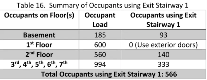
6. Estimate building evacuation time: The total population on each floor is shown in Table 3. The
population that is using Exit Stairway 1 is summarized in Table 16. Dividing the population using Exit Stairway 1 by the flow capability of Exit Stairway 1 of 44 persons/min. results in a total of 12.86 minutes to discharge through the Exit Stairway Door.
Table 16. Summary of Occupants using Exit Stairway 1 Occupants on Floor(s) Occupant
Load
Occupants using Exit Stairway 1
Basement 185 93
1st Floor 600 0 (Use exterior doors)
2nd Floor 560 140
3rd, 4th, 5th, 6th, 7th 994 333
Total Occupants using Exit Stairway 1: 566
24
3.
Suppression System Analysis
A wet automatic sprinkler system is located on all floors of the building and in the basement parking garage. Three wet standpipes are provided in the building and are spaced evenly in the north-west direction in each of the exit stairways that span most of the building. The standpipe in the middle of the building is a combination standpipe and riser that supplies the sprinkler system. Appendix D contains drawings with markups detailing the location of the standpipes. A fire pump is provided in the basement. The sprinkler system is designed and installed in accordance with NFPA 13 2016.
3.1
Automatic Sprinkler Systems
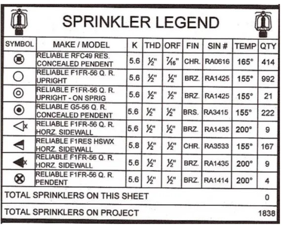
An automatic sprinkler system in accordance with 2016 NFPA 13 and 2017 NFPA 25 is installed
throughout the building. The system is equipped with several types of sprinkler heads, as shown in the sprinkler legend in Figure 11. Most sprinklers are quick response, ½ inch orifice, K=5.6 spray sprinklers. Various sprinkler head types are provided including concealed, pendent, upright and horizontal sidewall.
Figure 11. Sprinkler Legend
3.1.1
Classification of Sprinkler System Occupancy Hazard Groups
25 • Light Hazard: Corridors, hotel rooms, offices, restrooms, restaurant and bar seating areas, hotel
lobby, residential
• Ordinary Hazard Group 1: Parking garage, restaurant and hotel service areas, laundry areas, trash rooms, mechanical and electrical rooms, storage rooms
• Ordinary Hazard Group 2: Exterior loading dock, mercantile, tenant spaces (for future flexibility and to avoid upgrading the system if tenants change)
3.1.2
System Design Criteria
The design criteria for the systems are required to be in accordance with NFPA 13 Figure 11.2.3.1.1. Applicable design criteria for the Chicago Hotel are summarized below. Due to the use of quick
response sprinklers and a ceiling height of 12 feet, the design area can be reduced according to NFPA 13 11.2.3.2.3.1 by 37%. Typically, the design areas for light hazard and ordinary hazard are 1500 sqft, but with the reduction for quick response sprinklers the design area used will be 945 sqft.
• Light Hazard: 0.10 gpm/sqft over 945 sqft. Hose allowance of 250 gpm. Water supply for 60 minutes
• Ordinary Hazard Group 1: 0.15 gpm/sqft over 945 sqft. Hose allowance of 250 gpm. Water supply for 60 minutes
• Ordinary Hazard Group 2: 0.20 gpm/sqft over 945 sqft. Hose allowance of 250 gpm. Water supply for 60 minutes
3.2
Water Supply
The Chicago Water Department provides the water supply available to the Chicago Hotel. The water supply has the following characteristics as determined during flow testing.
• Static PSI: 39 • Residual PSI: 36 • Flow (GPM): 4250
The water supply is adequate for the required duration and flowrates. NFPA 13 11.2.3.1.2 requires 250 gpm for the hose stream requires for 60-90 minutes to be provided for Ordinary Hazard occupancies.
3.3
Fire Pump
The fire pump room is located in the parking garage in the basement of the building. The fire pump has the following characteristics:
• Type: Horizontal Split-Case • Flow (GPM): 1,000
• Rated Head Capacity (PSI): 110 • Churn (%): 120
• Motor Data (V/PH/HZ): 480/3/60 • Motor (HP): 100
• Motor (RPM): 3550
3.4
Fire Department Connections
26
3.5
Hydraulic Calculation
Two areas were calculated to ensure that the most demanding hydraulically remote location in the building is evaluated. The areas are both on the 7th floor, with one on the far North side and one on the
far South side. The area on the North side is in a mechanical penthouse room. The area on the South side is in a tenant space. These areas are summarized in Table 17 and are shown in the drawings located in Appendix D.
Table 17. Hydraulic Calculation Design Areas
Area Occupancy Design
Area
Discharge Density
Mechanical Penthouse Ordinary Hazard Group 1 945 sqft 0.15 gpm/sqft Tenant Space Ordinary Hazard Group 2 945 sqft 0.2 gpm/sqft
Sprinkler head and branch lines were laid out in the areas according to NFPA 13 installation requirements. The hydraulic calculation results are included in Appendix F for the mechanical penthouse room and in Appendix G for the tenant space. HASS (Hydraulic Analyzer of Sprinkler
Systems) calculation software was used for the hydraulic calculation. HASS is developed by HRS Systems, Inc. for professional use and is used in over 50 countries. The calculation used is based on the Hazen-Williams method. The hydraulic calculation required the distance, number of elbows, size of pipes, etc. to determine the pressure loss as the water moves through the sprinkler pipes from the pump to the remote area. At the beginning of each appendix section, there is a diagram indicating the layout of the hydraulic design area and the corresponding nodes that are used in the software calculation.
27 Figure 12. Level 7 Mechanical Penthouse Hydraulic Supply and Demand Curve
28 The system flow demand for the mechanical penthouse at the discharge side of the pump is 189 gpm at 110 psi. An additional 250 gpm has been added as the hose allowance at the source. A safety margin of 73.3 psi below the combined city and fire pump curve has been provided.
The system flow demand for the tenant space at the discharge side of the pump is 264 gpm at 84.3 psi. An additional 250 gpm has been added as the hose allowance at the source. A safety margin of 95.6 psi below the combined city and fire pump curve has been provided.
Table 18. Hydraulic Calculation Results Area Required
Pressure
Available Pressure
Required Flow Mechanical Penthouse 110 psi 183.3 psi 439 gpm Tenant Space 84.3 psi 179.9 psi 514 gpm
3.6
Inspection, Testing & Maintenance
Inspection, testing and maintenance for the automatic sprinkler system is required by NFPA 13 and NFPA 25, Standard for the Inspection, Testing and Maintenance of Water-Based Fire Protection Systems. This responsibility falls on the building owner. It is recommended to hire a sprinkler contractor with knowledge of sprinkler systems to assist in the required inspection, testing and maintenance. Table 19 provides a summary of inspection, testing and maintenance requirements for applicable sprinkler system equipment for the Chicago Hotel per the 2017 edition of NFPA 25. General summary tables on the frequency of testing required by NFPA 25 can be found in Appendix I.
Table 19. Sprinkler System Inspection, Testing & Maintenance Requirements per NFPA 25 Sprinkler System Component Inspection, Testing & Maintenance Requirements
Sprinklers Inspection: 5.2.1
Testing: 5.3.1 Maintenance: 5.4
Inspection frequencies shall follow NFPA 25 Table 5.1.1.2 (attached below).
Sprinklers shall be inspected from the floor level annually and checked for signs of leakage, corrosion, physical damage, loss of fluid in the glass bulb, loading, or paint. Spare sprinkler supply shall be checked annually.
Fast-response sprinklers should be tested at 20 years after
installation, and then at 10-year intervals. Not less than 4 sprinklers or 1 percent of the number of sprinkler per individual sprinkler sample, whichever is greater.
A supply of at least 6 spare sprinklers shall be maintained
Components requiring maintenance action shall conform to NFPA 25 Table 5.5.1 (included in Appendix I)
Pipe and Fittings Inspection: 5.2.2 Maintenance: 5.4
29 Sprinkler System Component Inspection, Testing & Maintenance Requirements
Components requiring maintenance action shall conform to NFPA 25 Table 5.5.1 (included in Appendix I)
Hangers, Braces, and Supports Inspection: 5.2.3 Maintenance: 5.4
Inspected annually from the floor level and checked to ensure that they are not damaged, loose, or unattached.
Waterflow Alarm and Supervisory Signal Initiating
Device Inspection: 5.2.4
Testing: 5.3.2 Maintenance: 5.4
Inspected quarterly to verify they are free of physical damage Mechanical waterflow alarm devices shall be tested quarterly. Vane-type and pressure switch-Vane-type shall be tested semiannually.
Components requiring maintenance action shall conform to NFPA 25 Table 5.5.1 (included in Appendix I)
Signs
Inspection: 5.2.5-5.2.9
Signs shall be inspected annually to verify they are present, securely attached, and legible.
Components requiring maintenance action shall conform to NFPA 25 Table 5.5.1 (included in Appendix I)
Standpipe and Hose System Inspection: 6.2
Testing: 6.3 Maintenance: 6.4
Inspection frequencies shall follow Table 6.1.1.2 of NFPA 25 (attached below)
A flow test shall be conducted every 5 years on all automatic standpipe systems to verify that the required flow and pressure are available at the hydraulically most remote hose valve outlets while flowing the standpipe system demand.
30
4.
Fire Alarm and Detection
A fire alarm system is required by the IBC due to the hotel occupancy (R-1) and the buildings high-rise classification.
Fire alarm design drawings of the building are included in Appendix J. It is important to note that the fire alarm drawings provided for the Chicago Hotel were developed according to the Chicago Building Code which may have differences compared to the International Building Code and installation requirements of NFPA 72.
4.1
Operating Characteristics of the Fire Alarm System
According to IBC 907.2.8 and IBC 403.4.2 R-1 occupancies (hotel) and high-rise buildings require a fire alarm system. Additionally, per IBC 403.4, high-rise buildings require an approved emergency
voice/alarm communication system that can broadcast pre-recorded voice instructions or live voice commands from the fire command center.
The system uses addressable initiating devices including smoke detectors, heat detectors, duct detectors, and waterflow switches. The system uses various notification appliances including combination strobe and speaker units, strobe only unit, or speaker only units. The notification
appliances are also used for the emergency voice/alarm communication system. IBC 907.2.11 requires smoke alarms that sound a local alarm only in each guest room. The smoke alarms may be addressable to the fire alarm control panel to indicate the location of the activated smoke alarm. Automatic smoke detection must be provided for the interior corridors that serve the sleeping units (rooms) of the hotel. The high-rise designation requires a fire command center located in an approved location.
The fire alarm system requires secondary power in case the main power supply is interrupted. The fire alarm system will activate from automatic fire detectors, automatic sprinkler system waterflow devices, manual fire alarm boxes, and automatic fire-extinguishing systems.
4.2
Fire Alarm Control Panel and Fire Command Center
The fire command center contains the fire alarm control panel, an elevator panel, and the firefighter smoke control panel for elevator and stairway pressurization systems. Per section 911.1.1 in the IBC, the location and accessibility of the fire command center shall be approved by the fire chief.
The fire command center and fire alarm control panel is located on the first floor, in the main entrance lobby on the east side of the building. The fire alarm control panel is a Siemens FireFinder XLS.
Additionally, there is an XLS remote panel on the 5th floor in the electrical room on the north side of the
building.
31
4.3
Fire Detection and Initiating Devices
The Chicago Hotel is provided with addressable smoke detectors, heat detectors, and duct smoke detectors. Table 20, below, lists the detection devices, their symbol, and the model of the device. Smoke alarms, which are not connected to the fire alarm system, are also provided.
Table 20. Installed Fire Detection Devices
Symbol Detection Device Model Quantity
Addressable Smoke Detector FD0421 W/ DB-11 52
Addressable Heat Detector FDT421 W/ DB-11 8
Addressable Duct Smoke Detector FDBZ492/FDO421/ST-100 5
Sprinkler Waterflow Switch By Others 12
Fire detection/initiating devices have location, spacing, and placement requirements according to NFPA 72 and the IBC. Table 21 and Table 22 summarize the location, spacing, and placement requirements and lists the corresponding code section. Detection devices are provided in the proper locations of the building except for required smoke detectors in interior corridors serving sleeping units, as shown on the fire alarm drawings in Appendix J. Duct detector locations were not verified due to absence of mechanical drawings and knowledge of the HVAC system.
Table 21. Required Locations of Fire Detection Devices
Required Location Code Section In R-1 occupancies, single- or multiple-stations smoke alarms shall be provided in
sleeping areas, every room in the path of the means of egress from the sleeping area to the door leading from the sleeping unit, in each story within the sleeping unit
IBC 907.2.11.1
In high-rise buildings, smoke detectors shall be provided in each mechanical equipment, electrical, transformer, telephone equipment or similar room that is not provided with sprinkler protection and in each elevator machine room, machinery space, control room and control space and in elevator lobbies.
IBC 907.2.13.1.1
In high-rise buildings, duct smoke detectors complying with section 907.3.11 shall be located in:
1. The main return air and exhaust air plenum of each air-conditioning system having a capacity greater than 2,000 cubic feet per minute (cfm) (0.94 m3/s).
Such detectors shall be located in a serviceable area downstream of the last duct inlet.
2. At each connection to a vertical duct or riser serving two or more stories from a return air duct or plenum of an air-conditioning system. In Group R-1 and R-2 occupancies, a smoke detector is allowed to be used in each return air riser carrying not more than 5,000 cfm (2.4m3/s) and serving not more than 10
air-inlet openings.
32 Required Location Code Section In R-1 occupancies, an automatic smoke detection system that activates the
occupant notification system in accordance with Section 907.5 shall be installed throughout all interior corridors serving sleeping units.
IBC 907.2.8.2
Not fewer than one manual fire alarm box shall be provided in an approved location to initiate a fire alarm signal for fire alarm systems employing automatic fire detectors or waterflow detection devices.
IBC 907.2.8.1
Table 22. Spacing and Placement Requirements of Fire Detection Devices
Spacing/Placement Requirement Code Section Initiating devices must be installed in accessible areas for periodic
maintenance
NFPA 72 17.4.2 and 17.4.5 Initiating devices must be protected when subject to mechanical damage NFPA 72 17.4.3 Detectors cannot be recessed into a mounting surface unless they are listed
for such mounting
NFPA 72 17.5.1 Spaces separated by partitions must be considered as separate rooms where
partitions extend to within 15% of the ceiling height
NFPA 72 17.5.2 Heat sensing detectors are spaced according to the listed space based on fire
testing specified in UL 521. The spacing depends on the shape of the space, height of the ceiling, slope of the ceiling, beam construction, and solid joist construction.
NFPA 72 17.6.3
On smooth ceiling heat sensing detectors must not exceed their listed spacing, and there shall be detectors within a distance of one-half the listed spacing, measured at right angles from all walls or partitions extending upward to within the top 15 percent of the ceiling height. All points on the ceiling shall have a detector within a distance equal to or less than 0.7 times the listed spacing (0.7S).
NFPA 72 17.6.3.1.1
On ceilings 10 ft to 30 ft (3.0 m to 9.1 m) high, heat detector spacing is required to be reduced in accordance with Table 17.6.3.5.1 prior to any additional reductions for beams, joists, or slope, where applicable.
NFPA 72 17.6.3.5.1
Spot-type smoke detectors must be located on the ceiling or, if on a sidewall, between the ceiling and 300 mm (12 in.) down from the ceiling to the top of the detector.
NFPA 72 17.7.3.2.1
On smooth ceilings, smoke detectors must not exceed a nominal spacing of 30 ft (9.1 m) and there shall be detectors within a distance of one-half the nominal spacing, measured at right angles from all walls or partitions extending upward to within the top 15 percent of the ceiling height. All points on the ceiling shall have a detector within a distance equal to or less than 0.7 times the nominal 30 ft (9.1 m) spacing (0.7S)
NFPA 72 17.7.3.2.3.1
Other spacing of smoke detectors is permitted depending on ceiling height, different conditions, or response requirements.
33
4.4
Fire Scenario and Expected Response
In this section of the report, an appropriate fire scenario is identified and analyzed to determine the expected response of the fire detection devices installed in the Chicago Hotel. Additionally, the size of the fire will be calculated at the time of detector activation. A fire originating in a hotel room poses an expected and reasonable fire location. Ceiling heights in the hotel rooms are 10 feet. Hotel rooms are typically occupied during normal sleeping hours and are less occupied during the day. Staff are present at all times, but during the night it is likely that there are fewer staff working. Potential ignition sources include faulty electronics, smoking, heating equipment, and arson among others. In this fire scenario, a 26 inch king-size mattress is assumed to be ignited. The fire grows as a slow t-squared fire with a fire growth coefficient of α=0.003 kW/s2.
In order to understand the impact of the fire on the building and building occupants, it is necessary to calculate when a sprinkler would activate, which subsequently would activate the notification
appliances via the waterflow switch. While there are smoke alarms in the sleeping units, they are not connected to the fire alarm system and do not activate the notification appliances. The DETACT method is used to calculate the anticipated response. The inputs necessary to run the calculation include ceiling height, radial distance based on the spacing of the smoke detectors, ambient temperature, fire growth power, fire growth coefficient, and the response time index (RTI). Figure 14 shows the typical layout of a guest room with an estimated distance of 8 feet 9 inches (2.7 m) from the location of the bed to the sidewall sprinkler. This value of 2.7 m is used as the radial distance, R.
Figure 14. Typical Hotel Room Layout
Table 23 shows the inputs/assumptions used for this calculation. The ceiling height is actually based off of the ignition location; since the ignition source was 26 inches above the floor on a bed the distance for this input is the 26 inch bed subtracted from the 10 foot ceiling height (10’ – 2’ 2” = 2.39 m). The activation temperature of the sprinkler is 68 degrees Celsius. There was no response time index (RTI) provided on the manufacturer data sheet so an RTI of 50 (m*s)1/2, which is typical for quick-response
sprinklers, was chosen.
Table 23. Input Parameters for DETACT Calculation
INPUT PARAMETERS CALC. PARAMETERS
34
INPUT PARAMETERS CALC. PARAMETERS
Radial distance (R) 2.7 m dT(cj)/dT(pl) 0.279
Ambient temperature (To) 20 C u(cj)/u(pl) 0.182
Actuation temperature
(Td) 68 C
Response time index
(RTI) 50 (m-s)1/2
Fire growth power (n) 2 -
Fire growth coefficient (k) 0.003 kW/s^n
Time step (dt) 0.5 s
Table 24. DETACT Calculation Results Calculation time (s) HRR Gas
temp
Gas velocity Det temp dT/dt
360 388.8 78.8 1.00 67.95 0.2169
360.5 389.9 78.9 1.00 68.06 0.2170
Based on the calculations obtained from the DETACT model, the sprinkler would activate approximately 361 seconds after ignition. Upon activation of the sprinkler, the fire would have grown to a heat release rate of 390 kW. After activation of the sprinkler, the waterflow switch would initiate the notification appliances throughout the Chicago Hotel.
4.5
Alarm, Supervisory, and Trouble Signals
The requirements for the disposition of alarm, supervisory and trouble signals are in NFPA 72 Chapter 10. This involves the fire alarm control panel receiving alarm, supervisory, and trouble signals from throughout the Chicago Hotel, the necessary response from the panel, and other associated
requirements. Priority alarms, fire alarms, supervisory signals, and trouble signals are required to be distinctively and descriptively annunciated in accordance with NFPA 72 10.10.1.
Alarm Signal
Per NFPA 72 10.11.1, actuation of alarm notification appliances or emergency voice communications, emergency control function interface devices, and annunciation at the protected premises is required to occur within 10 seconds after the activation of an initiating device. Protected premises fire alarm control units are required to be capable of being reset or silenced only from the fire alarm control unit at the protected premises according to NFPA 72 23.8.2.9. If the AHJ approves it, remote resetting from another location is allowed according to NFPA 72 23.8.2.10. Resetting procedures are required to be documented and permanently posted beside each control unit and annunciator.
When an alarm signal has been deactivated at the protected premise, the audible and visible alarm signal at the control panel only is required to automatically reactivate every 24 hours or less until alarm signal conditions are restored to normal according to NFPA 72 10.11.8.1. The audible and visible alarm sign is required to operate until it is manually silenced or acknowledged according to NFPA 72 10.11.8.2. When an alarm signal has already been received, subsequent actuation of addressable and
35 If the fire alarm notification appliances are deactivated and the deactivation means remains in the deactivated position when there is no alarm condition, it is required by NFPA 72 10.12.6 to operate an audible trouble notification appliance until the means is restored to normal.
Supervisory Signal
According to NFPA 72 10.13.1 and 10.13.2, self-restoring and latching supervisory signals are required to provide visible and audible indication with 90 seconds at the fire alarm control unit for local fire alarm systems, the building fire command center for in-building fire emergency voice/alarm communication systems, and the supervising station location.
If the supervisory notification appliances are deactivated and the deactivation means remains in the deactivated position when there is no supervisory condition, it is required by NFPA 72 10.13.7.5 to operate an audible trouble notification appliance until the means is restored to normal.
Trouble Signal
Trouble signals are required to be indicated within 200 seconds at the fire alarm control unit for local fire alarm systems, the building fire command center for in-building fire emergency voice/alarm
communication systems, and the supervising station location according to NFPA 72 10.14.1, 10.14.7 and 10.14.8. An audible trouble signal is allowed to be intermittent provided it sounds at least once every 10 seconds with a minimum duration of ½ second. A single audible trouble signal is permitted to indicate multiple fault conditions.
When a trouble signal has been deactivated at the protected premise, the audible and visible trouble signal at the control panel only is required to automatically reactivate every 24 hours or less until trouble signal conditions are restored to normal according to NFPA 72 10.14.9.1.
When a trouble signal has already been received, subsequent trouble signals are required to reactivate the notification appliances as required by the system input/output matrix in accordance with NFPA 72 10.14.10.5.
If the trouble notification appliances are deactivated and the deactivation means remains in the
deactivated position when there is no trouble condition, it is required by NFPA 72 10.14.10.6 to operate an audible trouble notification appliance until the means is restored to normal.
4.6
Notification Devices
Notification devices are installed to provide stimuli for initiating emergency action and provide information to users, emergency response personnel, and occupants. The Chicago Hotel has several forms of notification devices installed. Table 25 lists the notification device, symbol, model, and quantity installed.
Table 25. Installed Notification Devices
Symbol Notification Device Model Quantity