Prosthetic Thumb Design
A Senior Project
presented to
the Faculty of the Engineering Department
California Polytechnic State University – San Luis Obispo
In Partial Fulfillment
of the Requirements for the Degree
Biomedical Engineering
By
Allison Sigdestad, Sahil Sharma, Cale Foreman
Table of Contents
1.0 Executive Summary 3
2.0 Statement of Work 4
2.1 Introduction 4
2.2 Background 4
2.3 Objectives 7
2.4 Engineering Specifications 10
2.5 Project Management 11
2.6 Conclusion 13
3.0 Network Diagram 13
4.0 Indications for Use 13
5.0 Budget 13
6.0 Customer Requirements 15
7.0 Specification Requirements 15
8.0 TAM and Competitive Advantage 15
9.0 Intellectual Property Assessment 16
10.0 Conjoint Analysis 16
11.0 Morphology 18
11.1 Concept Design I 19
11.2 Concept Design II 20
11.3 Concept Design III 20
12.0 Concept Evaluation 21
13.0 Conceptual Model 22
14.0 Detailed Design 24
14.1 Detailed Design I 24
14.2 Detailed Design II 26
15.0 Prototype Manufacturing Plans 28
16.0 Test Protocols 35
16.1 Tensile Testing 38
16.2 Compression Testing 39
16.3 Attached Segments in Hyper-Extension 40
16.4 Water Testing 40
17.0 Testing Data and Analysis 41
17.1 Tensile Testing 41
17.11 Conclusion 44
17.2 Compression Testing 44
17.21 Conclusion 52
17.3 Hyper-Extension Testing 55
17.31 Conclusion 58
17.4 Water Testing 59
18.0 Patient Fitting 59
19.0 Conclusions 60
20.0 Discussion 61
21.0 Appendix 62
1.0 Executive Summary -
The Prosthetic Thumb Project is a senior design project completed by Biomedical Engineering Undergraduate students at California Polytechnic State University. This senior design project is aimed at designing a prosthetic thumb for a Cal Poly Pomona student who lost their thumb in an accident last year. The patient has ultimately lost between 30-40% of functionality of his left hand, and so we would like to give him that mobility back. Originally, the patient was worried about having a prosthesis, and wanted something more stagnant that would resemble the look of the thumb he lost. However, after working with him, we determined that in order to regain functionality of the left hand, he would need a body-powered prosthesis that will move with his thumb residual in order to mimic the natural motion of a hand. Since we are designing a product for our customer, we still wanted to make a design that does not entirely look mechanical.
The patient expressed a few specific needs and expectations for his new prosthesis. The patient ideally wanted to be able to perform everyday tasks that he used to, but now is unable to do. These included the ability to fit his hand, with the prosthetic thumb attached, into his pocket and have the ability to grasp items in the pocket. Other specified expectations include a low cost, lightweight-slim design, high durability, and an ability to still weight-lift. However, we do not believe we will be able to produce a prosthetic for weight lifting because of time constraints but instead we will provide suggestions for alternative devices to aid in weightlifting, but the main focus of this design should be for a day to day functional prosthetic.
After brainstorming and weighing all of our original design ideas, we decided to move forward with a prosthetic design that used hinges in order to drive the motion of the thumb. The hinge uses four points and four linkages in order to do so. The distal points are anchored distal of the IP joint while the proximal two points are anchored proximal to the IP joint. Depending on how much movement the patient has of the residual thumb distal to the MCP joint, the proximal anchor points of the prosthetic can be shifted back to sit over the MCP joint. However, upon meeting with our project sponsor, he informed us that there was most likely not enough residual left to drive that motion, and so our project decided to change to a mechanical wire driven prosthetic. A wire will connect to a wrist strap, and sit atop the proximal piece. The wire will be inserted inside the prosthetic, and wrap around an internal cam that will thus drive the forward and backwards motion of the prosthetic. As the proximal piece is moved forward by the motion of the residual, the cable will get shorter pulling the lever down, and pushing the distal piece down. This wire was incorporated into a design that resembled the human thumb by taking a 3D scan of the patients non-injured hand, mirroring it, and then cutting away the excess pieces to create a prosthetic that will match patients form. By doing so, we were able to have a body-powered prosthesis that does not have a mechanical appearance and roughly resembles the patients normal thumb.
2.0 Statement of Work -
Attached below is the Statement of Work for the Prosthetic Thumb Project. It outlines our project problem, deliverables and timeline for completing the design and product of a custom fit prosthetic thumb.
2.1 Introduction:
The Prosthetic Thumb Project is a six month long senior design project being completed by three California Polytechnic State University, San Luis Obispo students, and one California Polytechnic State University, Pomona student. The project is aimed to design a custom fit mechanical prosthetic thumb for a student with an amputee just above the metacarpal (MCP) joint.
2.2 Background:
Table 1: Partial Hand Prosthesis Currently on the Market.
Product Name Description Pros Cons
Thumb Driver (Naked Prosthetics) Body-Powered Prosthesis
Tracking natural CMC motion allows for the majority of motion, rigid structure that allows the hand to grasp objects
Interchangeable suspension rings allow patients to have an ideal fit. Cage-like structure of the linkages provide increased protection for the residuum/distal end of the amputation (can be
hypersensitive).
Tracks the natural multi-axial motion of the thumb complex
Must have enough residuum to engage the ring.
Minimum 6 week lead time.
PIP Driver (Naked Prosthetics) Body-Powered Prosthesis
For partial finger amputees (through the middle or distal phalanx), rigid linkage that is
self-suspended on the base of the finger residuum. The prosthetic joints line up with anatomic ones to provide natural motion/form
Lightweight, custom designed, strong.
Can be connected with other Naked Prosthetic devices. Silicone rubber tip pads resemble natural fingertips (and come in a variety of colors).
Must have enough residuum to engage the ring.
Minimum 4-6 week lead time. Not used for thumb
amputations.
MCP Driver (Naked Prosthetics) Body-Powered Prosthesis
Designed for amputations through the proximal phalanx (restores middle and distal phalanges), designed to restore power grasps and grip stability
Abduction/adduction washers allow the user to adjust mechanical fingers, and the patient can gain optimal grip. Strength and functional force (1-9 lb force at each fingertip). Lift substantial weight, and transfer load to suspension on wrist.
Must have enough residuum to engage the ring.
Minimum 6-8 week lead time. Not used for thumb
amputations.
Living Skin (Ossur)
Passive Partial Designed to be unnoticed. Designed for patients with finger, hand, arm, toe, and foot deficiencies.
Cosmetic.
Hand-painted and hand-crafted to match patients anatomy and skin tone.
Functional capabilities: pushing, pulling, stabilizing, supporting, light grasping, typing.
No movement capabilities. Very limited functionality. Subject to Uncanny Valley Effect.
Silicone Finger and Partial Hand Prosthetics (Ottobock) Passive Partial
Natural, custom prosthetic system. Each product is tailored to the specific shape and skin color of the patient. This low profile option can be customized to include freckles, veins, and hair making it look as realistic as possible.
Cosmetic.
Wires in the fingers allow for manual positioning of the fingers. Very customizable.
No active movement capabilities.
Very Limited functionality. Subject to Uncanny Valley Effect.
Titan Series (Partial Hand Solutions) Passive Partial
Designed to meet the needs of the heavy duty user. Machined out of titanium, with a ratchet design that allows the user to manually position the joints in the most function position and provide a secure grasp.
Very Durable.
High functionality for a passive prosthesis.
Can be used for partial digit amputations and in complete absence of a finger or thumb. Titan Thumb features full rotation of the base.
Table 2: Prosthetic Patents
Patent Product Name Claim Issue Avoiding Problem
US Patent 9375319 (Granted June 28, 2016)
Bio-Mechanical Prosthetic Thumb
“...a thumb strap ring having a direct pivoting connection with the proximal end of the proximal phalanges; … and an anchoring portion having an operable connection with the thumb strap ring…”
This claim mentions how their prosthetic thumb uses a thumb strap to anchor the prosthetic to the hand. We would continue using a thumb strap in our design because the strap is too common of an anchoring method and the patent claims more about the design of the proximal and distal phalanges, specifically.
US Patent 7361197 (Granted April 22, 2008)
Prosthetic Hand Having a Conformal, Complaint Grip and Opposable, Functional Thumb
“The hand of claim 1 in which an activation system comprises a highly flexible flexion cable, one end of which being attached within the distal end of said thumb…”
This claim refers to the use of flexible flexion cables on the palmar side of the thumb. We were considering the use of cables to actuate our thumb. We could change our design to use rigid linkages instead.
US Patent 10016289 (Granted July 10, 2018)
Bio-Mechanical Prosthetic Thumb
“... the ring comprises a select one of a number of
interchangeable rings, each of the interchangeable rings having a diameter that is sized to receive a different sized residual thumb.”
Instead of using a ring that fits over the residual thumb, we could use a wrist strap as the primary anchoring method.
US Patent Application 20190183661 (Applied June 20, 2019)
Powered Prosthetic Thumb “… comprising a first worm wheel and a first worm gear in mechanical communication with the first worm wheel, wherein the actuator is configured to cause rotation of the digit about the first axis by causing rotation of the first worm gear.”
We may use gears, if cables do not work. We could utilize different types of gears or use linkages to transmit force across the digits, therefore avoiding the use of worm gears.
US Patent Application 20190290454 (Applied June 11, 2019)
Bio-Mechanical Prosthetic Finger with Y-Shaped Rocker
“... A method of fitting a customized prosthetic finger having a proximal ring configured to anchor to a patient's residual finger…”
This design uses a proximal ring used to anchor the prosthesis to the residual thumb. Since the patient’s residual thumb is not very large, we may include a wrist strap, or another securing method wrapping around the base of the hand.
US Patent Application 20170296360 (Applied October 19, 2017)
Bio-Mechanical Prosthetic Thumb
“The bidirectional prosthetic thumb device of claim 14, wherein the hand strap is configured for attachment about a hand of the user.”
The largest make up of amputees are partial hand amputees, accounting for nearly 75% ( National Academies of Sciences) . There is a difficulty in standardizing prosthetics, due to the nature of amputations. Each amputation can occur in a different location, severing different nerves, etc. which makes designing prosthetics as a mass product difficult to do. As 3D printed devices are becoming more popular due to lower cost and decreased production time, a few people have attempted to create body powered hand prosthetics. This could be used to customize each prosthetic to the user. A highly advanced 3D printed hand was printed using a MakerBot Replicator. The device is called the Raptor Reloaded 3D printed body powered prosthesis (Case Comparison of Electric…). While this device did not perform as well as an electric prosthetic hand device, it was still able to grasp objects due to movement of the wrist. If we had access to a prestigious 3D printer, the option of designing and printing a prosthetic thumb would be a cheaper and faster option to produce for our patient.
For some individuals, the robotic look of body powered prosthetics is frightening. Therefore, for some patients with “limb loss, cosmetic restoration is highly valued or even preferred over functional restoration because of its mitigating effect on the disruption to body image” ( National Academies of Sciences) . However, a majority of these prosthetics are passive, meaning they do not serve a real function. Passive prosthetics are designed to look as if they naturally replace the missing limb. They are generally made out of silicone, and must be positioned how the user wants it (Rotter). For our device, our patient is self-conscious about the looks of a prosthetic, but wants the utility factor of a body powered prosthetic, and so we are tasked with finding a happy medium between the two.
The Food and Drug Administration (FDA) considers most upper limb prosthetics to be a Class I device. Class I devices have “minimal potential for harm and are specifically defined by the FDA as not intended to be for use in supporting or sustaining life, of importance in preventing impairment to human life, and may not present a potential unreasonable risk of illness or injury” (Resnik). The majority of marketed prosthetics in the past few decades have not had to go through FDA regulation requirements of “PMA and premarket notification [510(k)]” (Resnik). PMA is a FDA regulated premarket approval process, and premarket notification [510(k)] is a document proving that the device is safe to use and similar to a previously marketed device. Prosthetics however must undergo clinical trials (with humans). The FDA does not provide specific guidelines to the prosthetic industry, but companies must do human trials and “comply with Federal regulations through FDA/CDRH processes before they can be marketed within the United States as required by 21 CFR Parts 800-1299” (Resnik). The 21 CFR Parts 800-1299 contains the product regulations for medical devices and radiation emitting devices. A new prosthetic design must comply with these regulations as stated by the FDA (Center for Devices and Radiological Health).
2.3 Objectives:
the patient’s left thumb. This project will tackle this problem by developing a prosthetic thumb capable of restoring the functionality of the patient’s left hand.
The scope of this project includes developing a body powered prosthetic thumb that is capable of movement similar to that of the human thumb.This prosthetic will need to be securely attached to the patients hand and residual digit with a minimal amount of movement where the harness meets the hand. This harness will most likely include a strap that wraps around the base of the hand or wrist. The interface of the harness will need to be biocompatible with human skin to minimize irritation. Lastly, we will explore ideas of how to make this prosthetic capable of weightlifting applications, or design an attachment to accompany the existing harness. However, we will not explore any electrical options for the prosthetic due to the time frame and financial restrictions of the project. Also, we will not pursue making the prosthetic resemble the human anatomy cosmetically with the use of silicone and painting.
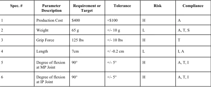
2.4 Engineering Specifications
Table 3: Engineering Specifications Spec. # Parameter
Description
Requirement or Target
Tolerance Risk Compliance
1 Production Cost $400 +$100 H A
2 Weight 65 g +/- 10 g L A, T, S
3 Grip Force 125 lbs +/- 10 lbs H T
4 Length 7cm +/ -0.2 cm L I, A
5 Degree of flexion
at MP Joint
90° +/- 5° H A, T, I
6 Degree of flexion
at IP Joint
90° +/- 5° H A, T, I
Production Cost: Ultimately, the functionality of the prosthetic thumb is of the utmost importance. If the prosthetic is not functional, nothing else matters. However, minimizing cost, while maximizing functionality is an important balance to find. Attempting to stay close to, or within, our proposed budget will be the best way for analyzing our spending. Production cost is currently rated as “High Risk” for a few reasons. First, we are still in the early stages of the design phase and do not have a solid idea of what materials will be necessary. Once we have a better idea of what our final design will look like, we will know specifically what materials and how much we will need.
Weight: The weight of the prosthetic thumb will be measured using a scale. We want the thumb to have a weight similar to that of the patient's actual thumb for ease of use and comfort.
Grip Force: Grip force will be measured using a hand grip dynamometer. This parameter is labeled as ‘High Risk” because not only is it crucial to the degree of functionality of the prosthetic, but it may also be our hardest parameter to achieve our target value. Applying excessive force to the prosthetic may cause it to articulate on the residual thumb, or even crack and compromise the integrity of the prosthetic.
Length:The length of the prosthetic will simply be measured using a ruler or small tape measurer. The only importance of this parameter is that it is similar to the thumb of the patient's right hand for consistency, aesthetics, and ease of use.
Degree of Flexion at MP Joint: The degree of flexion at the MP Joint will be measured using a protractor. The reason that the degree of flexion is labeled as “High Risk” is because it is essential to functionality. Additionally, an anatomically correct degree of flexion may prove difficult to achieve due to movement and the prosthetic-residual thumb interface.
2.5 Project Management:
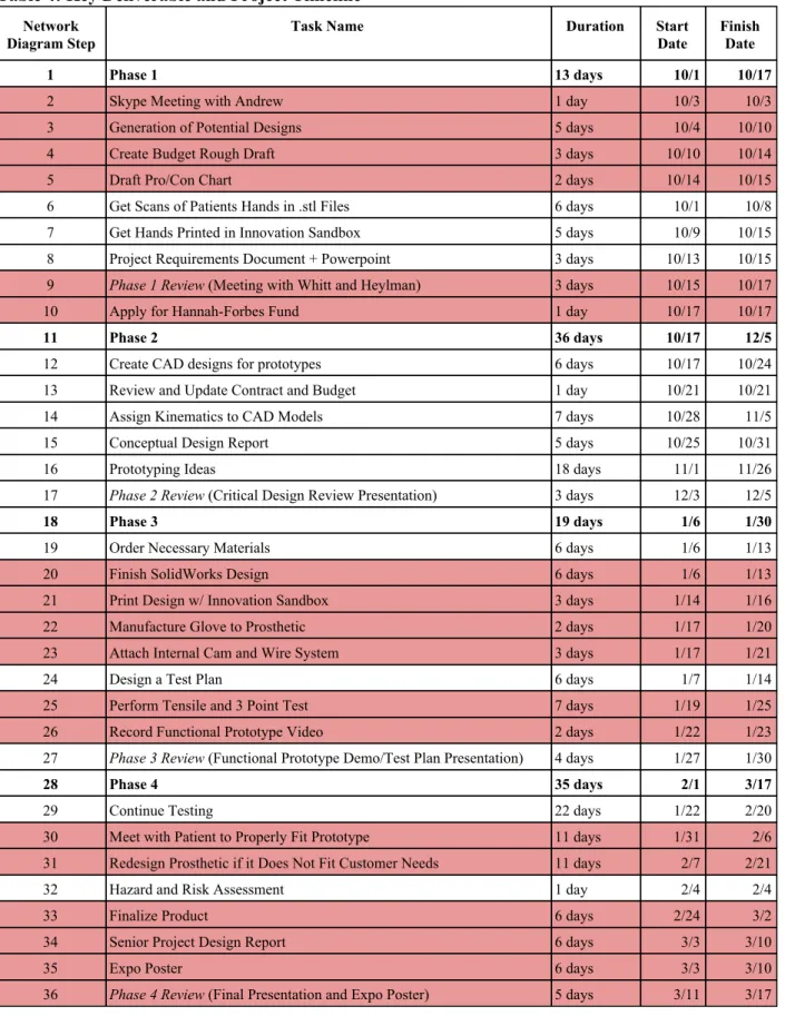
We plan to follow the overall design process shown below in Table 4. In order to build, fit and test our prosthetic thumb by March, 17 2019 we will need to stick to this strict timeline.
We have gained access to a broken Naked Prosthetic (PIP Driver), and we are using that to brainstorm ideas on how we want to design our thumb prosthetic. As shown above in the House of Quality, Naked Prosthetics perform well in the categories that our patient requires, and so we will use their design as inspiration when coming up with our own design. We have gotten scans of both the patient's hand (injured hand and non-injured hand), converted them to .stl files and have sent them to the innovation sandbox to be 3D printed. This will help us visualize and start to prototype directly on the hand. Finally, we have finished the necessary documentation (pro/con chart, budget sheet, etc.) to move forward with our project.
The next step in the process is to obtain the 3D printed hands, and begin building a prototype that can fit directly on the 3D models. We will also need to meet with the patient to discuss his desire for a prosthesis that he can weight lift with. After researching the topic more, we believe that our main focus should be on creating a day to day functional body powered prosthesis, as most amputees weight lift with hooks or loops they can attach to their wrist. We can discuss with him that if we have time at the end of the project, we could maybe create a new design, but that is not the main priority currently.
Table 4: Key Deliverable and Project Timeline Network
Diagram Step Task Name Duration Start Date Finish Date
1 Phase 1 13 days 10/1 10/17
2 Skype Meeting with Andrew 1 day 10/3 10/3
3 Generation of Potential Designs 5 days 10/4 10/10
4 Create Budget Rough Draft 3 days 10/10 10/14
5 Draft Pro/Con Chart 2 days 10/14 10/15
6 Get Scans of Patients Hands in .stl Files 6 days 10/1 10/8
7 Get Hands Printed in Innovation Sandbox 5 days 10/9 10/15
8 Project Requirements Document + Powerpoint 3 days 10/13 10/15 9 Phase 1 Review (Meeting with Whitt and Heylman) 3 days 10/15 10/17
10 Apply for Hannah-Forbes Fund 1 day 10/17 10/17
11 Phase 2 36 days 10/17 12/5
12 Create CAD designs for prototypes 6 days 10/17 10/24
13 Review and Update Contract and Budget 1 day 10/21 10/21
14 Assign Kinematics to CAD Models 7 days 10/28 11/5
15 Conceptual Design Report 5 days 10/25 10/31
16 Prototyping Ideas 18 days 11/1 11/26
17 Phase 2 Review (Critical Design Review Presentation) 3 days 12/3 12/5
18 Phase 3 19 days 1/6 1/30
19 Order Necessary Materials 6 days 1/6 1/13
20 Finish SolidWorks Design 6 days 1/6 1/13
21 Print Design w/ Innovation Sandbox 3 days 1/14 1/16
22 Manufacture Glove to Prosthetic 2 days 1/17 1/20
23 Attach Internal Cam and Wire System 3 days 1/17 1/21
24 Design a Test Plan 6 days 1/7 1/14
25 Perform Tensile and 3 Point Test 7 days 1/19 1/25
26 Record Functional Prototype Video 2 days 1/22 1/23
27 Phase 3 Review (Functional Prototype Demo/Test Plan Presentation) 4 days 1/27 1/30
28 Phase 4 35 days 2/1 3/17
29 Continue Testing 22 days 1/22 2/20
30 Meet with Patient to Properly Fit Prototype 11 days 1/31 2/6 31 Redesign Prosthetic if it Does Not Fit Customer Needs 11 days 2/7 2/21
32 Hazard and Risk Assessment 1 day 2/4 2/4
33 Finalize Product 6 days 2/24 3/2
34 Senior Project Design Report 6 days 3/3 3/10
35 Expo Poster 6 days 3/3 3/10
2.6 Conclusion:
This document serves as an outline for the scope of the project, and outlines the work that needs to be done. By the end of this project, we will have developed a lightweight but functional, body powered prosthetic thumb that is capable of movement similar to that of the human thumb. This prosthetic will be securely attached to the patients hand and residual digit with a minimal amount of movement where the harness meets the hand. The next project deliverable is to begin building a prototype for a body powered prosthetic thumb on the 3D printed hands that we will receive from the innovation sandbox in a few days. We are aiming for the prototype to be completed by January 31, 2020. As of January 37, 2020, a prototype has been completed and printed using the Innovation Sandbox. We have very minor changes to make from this prototype to our final design, and that is slightly increasing the tolerances on holes, but otherwise the SolidWorks design is finalized.
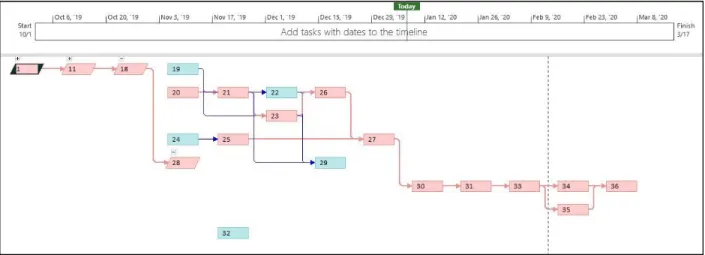
3.0 Network Diagram
In Microsoft Project, we input the tasks and deadlines that all components of the project need to be completed by. It outlined a network diagram that our team should follow in order to finish the prosthetic thumb design on time. Seen below in red is the critical path - the most important tasks that need to be completed that will result in the project being completed in minimum time. The specific steps are outlined above in Table 4 of the Statement of Work section.
Figure 2. Network Diagram.
4.0 Indications for Use
The Cal Poly Prosthetic Thumb Team has come up with the following indications for use for FDA approval of our device: This device will be used by an individual who has recently undergone a thumb amputation distal of the Metacarpal-Phalangeal (MCP) joint, in order to improve the overall functionality of the left hand. The degree to which functionality may be improved is largely dependent upon the length of residual thumb. Our team will design a lightweight prosthetic that the user can actively move and engage to mimic natural thumb movement, function, and strength.
5.0 Budget
Table 5. Proposed Budget.
Item Description Product Number
Associated Task
Planned
Unit Quantity Cost/Unit Total Cost
Shipping prototype 32 2-lb Box 2 $20 $40.00
3D Printed Shell (PLA) 19 1 10 $0.00 $0.00
PowerPro Hollow Ace 19 1 Yard 15 $0.75 $0.00
Button Head Torx Screws 18-8 Stainless
Steel, M2 x 0.4mm Thread, 5mm Long 90910A921 19 100 1 $11.60 $11.60
316 Stainless Steel Ring Shim 0.001"
Thick, 1/8" ID 97022A864 19 5 2 $9.09 $18.18
18-8 Stainless Steel Dowel Pin Stock 1/8"
Diameter 95609A310 19 1 1 $12.31 $12.31
TiN Coated High-Speed Steel Tap Set, M2
x 0.4 mm Thread 26475A11 19 1 1 $57.81 $57.81
Screwdriver T6 Torx 5756A32 19 1 1 $6.25 $6.25
302 Stainless Steel Torsion Spring 180
Degree Right-Hand Wound, 0.216" OD 9287K21 19 1 5 $3.83 $19.15
Narrow Fillister Head Slotted Screw 18-8 Stainless Steel, High-Profile, 2-56
Thread, 1/2" Long 91794A081 19 100 1 $5.31 $5.31
Short-Length Drill Bit
1.6mm Size, 33mm Overall Length 2979N13 19 1 2 $3.81 $7.62
Tap Wrench with Fixed Straight Handle,
5" Long 2546A12 19 1 1 $46.24 $46.24
Plastic Box
with 12 Compartments, 10-3/4" x 6-1/2" x
1-7/8", Clear 19 1 1 $8.84 $8.84
Delrin® Acetal Resin Balls
1/16" Diameter 9614K5 19 25 1 $4.97 $4.97
18-8 Stainless Steel Screw-to-Expand Insert for Plastic
2-56 Thread Size 92394A111 19 10 2 $10.14 $20.28
High-Performance Fabric 621596 19 2 Yards 1 $13.75/ yard $27.50
0.75" Elastic Spool B07G86CFJX 19 11 Yards 1 $7.99 $7.99
Ball Point Hand Needles B005573G3Q 19 48 Needles 1 $6.38 $6.38
Stretch Thread
B074N5CMP
G 19 225 Yards 1 $5.11 $5.11
Futuro Deluxe Thumb Stabilizer 19 1 $21.00 $21.00
Instron Tester (Tensile Testing) 21 1 $0.00 $0.00
Materials Tester (Flexural Testing) 21 1 $0.00 $0.00
Total: $326.54 Shipping/Travel
6.0 Customer Requirements
The patient expressed a few specific needs and expectations for his new prosthesis. These included the ability to fit his hand, with the prosthetic thumb attached, into his pocket and have the ability to grasp items in the pocket. Additionally, the patient prefers to have a body powered prosthetic rather than a passive-partial prosthetic with no active movement. Other specified expectations include a lightweight-slim design, high durability, and an ability to still weight-lift. Finally, we would like to create a low cost design, to keep the prosthetic at no cost to him. However, as of November 2nd, we do not believe we will be able to produce a prosthetic for weight lifting because of time constraints. We can provide suggestions for alternative devices to aid in weightlifting, but the main focus of this design should be for a day to day functional prosthetic.
7.0 Specification Development
The engineering specifications can be seen above in Table 3 of the Statement of Work section. Minimizing cost, while maximizing functionality is an important balance to find for our design. Attempting to stay close to, or within, our proposed budget will be the best way for analyzing our spending. Production cost is a “High Risk” specification because we are still in the early stages of the design phase and do not have a solid idea of what materials will be necessary. Once we have a better idea of what our final design will look like, we will know specifically what materials and how much we will need. The second most important specification is the weight of the device. This will be measured using a scale. We want the thumb to have a weight similar to that of the patient's actual thumb for ease of use and comfort.
8.0 TAM and Competitive Advantage
TAM: Individuals of any age and gender requiring enhanced functionality from their fingers. Around 30,000 people a year in the United States undergo a finger amputation (“How to
Avoid…”). Most amputations are generally due to accidents with doors and power tools. If we are estimating the cost of our product to be $200, it is estimated that we could make $6,000,000/year from our product.
SAM: Individuals who have some sort of amputation of any of their fingers in the California area. Around 12% of U.S. citizens live in California, so 12% of the 30,000 finger amputations a year should occur in California. This results in 3,6000 people a year in California have an amputation of their fingers. Therefore it is estimated that we could make $720,000/year from our product.
SOM: Individuals who have a thumb amputation distal to the MCP Joint and Proximal to the Interphalangeal joints.
Around 20% of finger amputations are of the thumb, and so 20% of 3,600 people is 720 people a year. This is the market that we are aiming to serve. We estimate that we would make
$144,000/year on our prosthetic thumb product.
For the current stage of this project, we are designing for the custom fit of one patient. This can later be expanded for more patients on a wider scale.
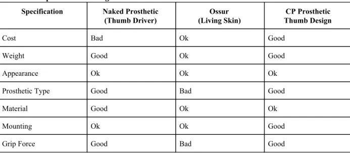
Table 6. Competitive Advantage.
Specification Naked Prosthetic
(Thumb Driver)
Ossur (Living Skin)
CP Prosthetic Thumb Design
Cost Bad Ok Good
Weight Good Ok Good
Appearance Ok Ok Ok
Prosthetic Type Good Bad Good
Material Good Ok Ok
Mounting Ok Ok Good
Grip Force Good Bad Good
9.0 Intellectual Property Assessment
Current products and pending patents were assessed to verify where intellectual property currently exists, and what design choices we may have to make when designing the prosthetic, so that we can be sure to avoid infringement. These assessments can be seen above, in the Statement of Work section, in Table 2 (patents and patent applications).
10.0 Conjoint Analysis
We completed a conjoint analysis to determine which attributes of the prosthetic thumb were most desirable. Seen below in Table 7, are the factors we weighed with the different levels. The level 0 factors are more desirable than the level 1 factors. We then made eight different design options, using each of the factors from the level 0 design and the level 1 design. Those options were turned into eight different conjoint cards, which can be seen below in Table 8.
Table 7: Factors and Levels of Prosthetic Thumb Design
Factor Level 0 Level 1
Cost $200-$500 $500-$1000
Weight 40-90 g >90 g
Appearance Mechanical Natural
Type Body Passive
Material Carbon Fiber Stainless Steel
Mounting Glove Thumb Strap
Table 8: Listing of Conjoint Cards
Card # Cost Weight Appearance Type Material Mounting Grip Force
1 0 0 0 1 1 1 1
2 0 0 0 1 1 1 1
3 0 1 1 0 0 1 1
4 0 1 1 1 1 0 0
5 1 0 1 0 1 0 1
6 1 0 1 1 0 1 0
7 1 1 0 0 1 1 0
8 1 1 0 1 0 0 1
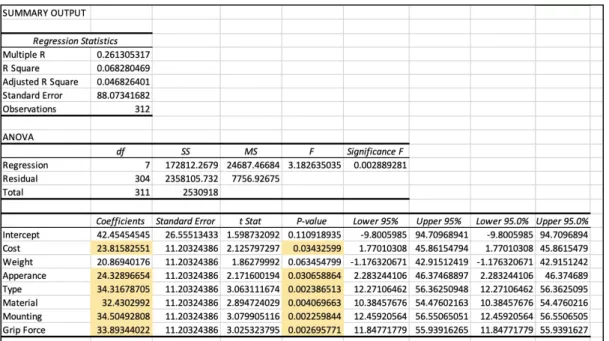
Thirty-nine of our classmates were surveyed and they ranked the conjoint card options from one to eight (one being the best option and eight being the worst option). That data was input into excel, and a
multivariate regression was run in excel. The excel statistical output can be seen below in Figure 3. Based
on the information from the multivariate regression, cost, appearance, type of prosthetic, material,
mounting and grip force are all important to the success of the product because their p-values are less than
0.05%. The coefficients add up to a total of 200 points, and to determine the most important factors we
look only at the statistically significant factors. Type of prosthetic and mounting have the highest
importance, at 17%. Since the coefficients are positive, this means that our peers believe that the level
zero factor is most important, so in this case, carbon fiber material and a glove mounting type should be
used in order to create a successful product. The only non-significant factor is the weight of the prosthetic,
however this is important to us as designers and to the patient. We will not throw out that factor, and will
still design the product with the intention of keeping the weight of the device as low as possible.
11.0 Morphology
Functional decomposition was used to generate a morphology for a prosthetic thumb design. The main functions of our thumb consist of how the prosthetic moves, how the prosthetic attaches to the thumb, and how the entire product will attach to the wrist. We are also worried about the cosmetic appearance of our device, because the patient has said that he is self conscious about the look of the industrial/robotic looking prosthetics. For active movement, the device needs to be able to move at the joints through the body powered movement when the patient moves the thumb residual. Three ways that we believe we can do this is through hinges, cables or a single joint. Another function that is essential to the product is how the prosthetic will attach to the thumb residue. Ideas we came up with include attaching it to a glove that the patient can wear, attaching it to a ring that sits on the residue, a plastic brace that can attach over the thumb and down the side of the hand, or with a single pin that locks and can be quick released. For attachment to the wrist, we want the patient to be able to do so with ease (he should be able to do it quickly with one hand). Velcro or d-ring loops seem to be the best options for that. Finally, for a cosmetic look, we are considering having no cover (the device would have exposed metal), a silicone sleeve or cover that has the appearance of a realistic thumb, or using paint to mask the metal. These concept ideas can be seen below in Table 9. After creating the morphology table, each team member was tasked with generating a design using the concept ideas from the table. The three designs we came up with can be seen below in Figures 4-6.
Table 9: Morphology Assessment
Morphology
Product: Prosthetic Thumb Organization Name: California Polytechnic State University
Function Concept 1 Concept 2 Concept 3 Concept 4
Active Movement (Body Powered)
Hinge Design Cable Design Single Joint
Design Linkage Design Attachment to Thumb Sewing/Gluing into Glove
Oval Ring Plastic Brace Locking Pin with
quick release
Attachment/ Detachment to
Wrist
Velcro Velcro + Loops Loops (D Ring)
Cosmetic
No covers Silicone
sleeve/cover
Skin Colored Paint
Team member: Sahil Sharma Team member: Allison Sigdestad
Prepared by: Sahil Sharma, Allison Sigdestad, Cale Foreman
11.1 Concept Design I
Figure 4. Concept Design I.
11.2 Concept Design II
Figure 5. Concept Design II.
Concept two uses a hinge design to provide active movement of the prosthetic thumb. The hinge uses four points and four linkages configured in the A, B, C, D system seen in the drawing. The distal points are anchored distal of the IP joint while the proximal two points are anchored proximal to the IP joint. Depending on how much movement the patient has of the residual thumb distal to the MCP joint, the proximal anchor points of the prosthetic can be shifted back to sit over the MCP joint. The prosthetic would be glued/epoxied to a sleeve that sits over and cushions the residual thumb. The sleeve can be made of a flexible fabric/gel. It has a cutout on one side to fit snugly around the residual thumb without interfering with the webbing between the thumb and index finger. The sleeve is permanently sewn onto the thumb strap/glove. The strap/glove is secured to the hand using a velcro strap around the wrist.
11.3 Concept Design III
Concept three is very similar to Concept one in how it functions, but with a more mechanical look. The main components include the prosthetic/thumb interface (silicone ring) where the device is actually in contact with the residual thumb, 4 stainless steel rods, thumb pad, and wire. The stainless steel rods will be connected via hinges, while the wire runs through the middle of the rods and connects to the thumb pad. As tension in the wire increases, the thumb pad will bend inward. At the moment, we are unsure of how exactly the user will increase wire tension to cause the bend at the joint.
12.0 Concept Evaluation
To evaluate the three concept designs generated, we used a pugh matrix. The pugh matrix compares each of the concepts against each other to determine a frontrunner. We used criteria from our QFD (House of Quality) to evaluate each of the concepts. An example of the empty pugh matrix can be seen below in Figure 7, however each of the team members filled out the pugh matrix and the results can be seen in the Appendix in Figure 65. Each team member filled out the matrixes individually, using one matrix as the baseline and comparing the other two concepts to that one. A score of -1 means that the evaluated concept performs worse than the baseline concept, a score of 0 means the two concepts perform the same, and a score of 1 means the evaluated concept performs better than the baseline concept. 100 points distributed to the five factors. Grip strength and load applied were weighted the highest, and each given 25 points because those are detrimental to the function of the prosthetic. Grip strength is the primary function of this prosthetic thumb. It also needs to be structurally sufficient to maintain the desired grip strength. If the prosthetic cannot withstand a load or apply strong grip strength the device is useless to the patient. Cost to manufacture was given 20 points, because we are looking to keep the device at a low cost. Finally weight and reliability were weighted the lowest, with 15 points each. While we want a low weight device that will last a long time, they are the least concern at the moment for creating a functional device for the patient.
Figure 7. Pugh Matrix.
important criteria for the prosthetic design. Because of this, we have decided that Concept 2 is our front runner, and we will continue forward with a design for this concept.
13.0 Conceptual Model
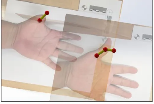
To better understand the movement that the prosthetic needs to match, a solidworks ball and model representation of the distal and proximal phalanges was generated by our Cal Poly Pomona counterpart. The model has been overlaid onto a 2D photo of the injured hand and angle constraints were inserted to mimic the motion of the patient's hand. Degrees of motion were taken from the patients physical therapist to ensure that the exact motion of the right thumb can be given to the left thumb prosthetic.
Figure 8. Ball and Stick 2D Model
The 2D model shows the patient's injured hand, and non-injured hand but flipped so that it also appears as the left hand. The joints and bones are modeled as a ball and stick model. As seen in the full hand, there are two bones and three joints. The degrees of motion of those balls were constrained using the values received from the patients physical therapist: Right thumb 1st joint can move from 0 degrees to 50 degrees (0 is upright position), and 2nd joint can move from 0 degrees to 70 degrees. The injured left hand 1st joint can move between 0 degrees and 35 degrees. We compared how this basic thumb model moves compared to our thumbs, and the movement was very accurate. We now have a SolidWorks model that accurately depicts the motion we would like the prosthetic to be able to do. Using this information, we can further our design by building a 3D model of the prosthetic design that we want to create directly on top of this current model. That way we can verify that the movement of the prosthetic design will match the movement needed by the thumb.
Figure 9. Ball and Stick 3D Model.
This model has the same idea as the previous model - it shows the movement of the bones and joints in the patient's full finger. In this case, the full model was inserted into the scan of the patient's injured hand. The patient still has the MCP joint, and so the bottom joint (ball) was inserted directly on top of it. This model shows how the prosthetic joints should line up with the amputated thumb, and also give us measurements on how long the distal and proximal sections should be given the residual length of thumb. As with the other model shown above, this will aid us when we build our prosthetic model on top of this current model, and verify that the segments are the correct length and the joints move as they should.
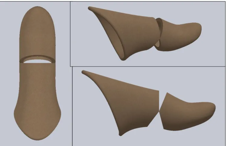
For this model, the mirrored 3D body of the right thumb was superimposed on the left hand. The thumb was converted into a proximal and distal phalanx, connected with a singular joint. The purpose of this solidworks model is to show how much of the proximal phalanx clips/collides with the residual thumb. We can also determine the contours of the socket that will seat the prosthetic against the hand. This is the model that we will change and build upon to create the realistic looking prosthetic device that can be 3D printed.
14.0 Detailed Design
14.1 Detailed Design I
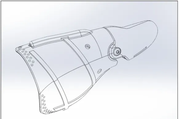
After meeting with our sponsor and Cal Poly Pomona counterpart, it was established that our concept design we wanted to move forward with would not be feasible for the active movement our patient desires. We believe that there is not enough residual of the thumb there to create a big enough moment to drive the motion of the prosthetic thumb using the hinge design, as we had previously believed. After receiving videos showing the patients range of motion, and discussing with Dr. Haghi, we decided to change the design of our prosthetic to using a wire based mechanism to drive the motion of the thumb. A cable system will allow the patient to generate and amplify larger motions of the prosthetic from the little residual that is left. Seen in Figure 11 is the outer shell of the prosthetic thumb. This will encase the wire and the internal cam mechanism that will drive the motion of the thumb.
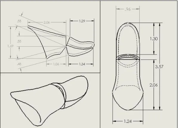
Figure 12. Outer Shell Dimensions.
Figure 13. Detailed Design I of Prosthetic Thumb.
will be to the wrist strap because the wrist strap will not be moving depending on the residual. The wire will connect to the wrist strap, sit atop the proximal piece, go inside and wrap around an internal cam that will thus drive the forward and backwards motion of the prosthetic. As the proximal piece is moved forward by the motion of the residual, the cable will get shorter pulling the lever down, and pushing the distal piece down. A torsion spring will be between the proximal and distal pieces. The spring will save space to mount the cable inside the tip of the thumb. The proximal and distal pieces will overlap with one another, and be held together with a washer, dowel pin and screw. The model will be split in half so that the wire and cam can be placed inside, and so that the patient can easily access the components if anything breaks or needs to be repaired.
Dimensions shown in Figure 12 above are not driving the design of the thumb. The dimensions were taken from the exact hand scan of the patient and converted into a .stl file. The right thumb was translated into a design for the left thumb so that the measurements exactly matched the patients biology. Pieces of the thumb were then cut away at the joint where the proximal and distal components meet so that the two parts do not interfere. The overall length of the thumb is 3.57 inches while the width is 0.96 inches, which fall within the normal range of thumb measurements.
For materials, we have decided to use PLA from the Innovation Sandbox for the outer housing of the prosthetic thumb. The lifetime for the product is only 1-2 years, and so we do not feel that it is necessary to proceed with carbon fiber and instead save costs. It held up to preliminary tests and seems strong enough and so we would like to use PLA. We may look into a primer to add a more sophisticated surface finish on the pieces, and also we have considered adding a rubber overmold or piece on the end of the thumb for gripping purposes. We will be using blind rivets to hold the proximal and distal pieces together. We intend on adding these pieces later on after the design has been proven to work. We have decided to use PowerPro Hollow Ace fishing line for the wire that will drive the motion of the thumb. This fishing line is much less expensive than the nylon wire we were considering and is already weighted to very high strengths. It is a braided line, and so it has little to no stretch which is ideal for our design. This particular fishing line is also meant to be run between your fingers, and therefore it is safe to handle and will not cause any damage or injury to our patient. For the internal cam, we will also be 3D printing using the PLA from innovation sandbox. Andrew will be continuing the project until May (after the SLO students are done with the project) and he has discussed maybe using CNC to manufacture an internal cam out of stainless steel. His reasoning is because it is a small enough piece where steel would not add too much weight to the device. Stainless steel would add an extra corrosion resistance, which is ideal to protect against any damp conditions such as water, rain or sweat. For our time purposes however, our BMED 456 final design will have a PLA internal cam.
14.2 Detailed Design II
Design II also changes from using the PowerPro Ace Hollow fishing line to a medical grade wire provided by Loos and Company. They gave us around 3 feet of free samples.
15.0 Prototype Manufacturing Plans
Seen below in Tables 9-10 is our Detailed Manufacturing Process Instructions (MPI). Table 10 includes documentation for manufacturing the proximal and distal phalanges, the glove and the cam. Table 11 includes documentation for assembling the prototype. All prototype manufacturing will take place at both the Pomona and San Luis Obispo campuses.
The facilities to be used for prototype manufacturing include Cal Poly Pomona campus and Cal Poly San Luis Obispo Campus. 3D printing will be carried out in the Innovation Sandbox located on the Cal Poly San Luis Obispo campus, using their 3D printers. The Innovation Sandbox is located in 197-205 (Bonderson Projects Center). The axle will be manufactured in the San Luis Obispo machine shops. The final prototype/product will be assembled on the San Luis Obispo campus. The San Luis Obispo students require yellow tag certification to use the machine shops.
Table 10: MPI Manufacturing
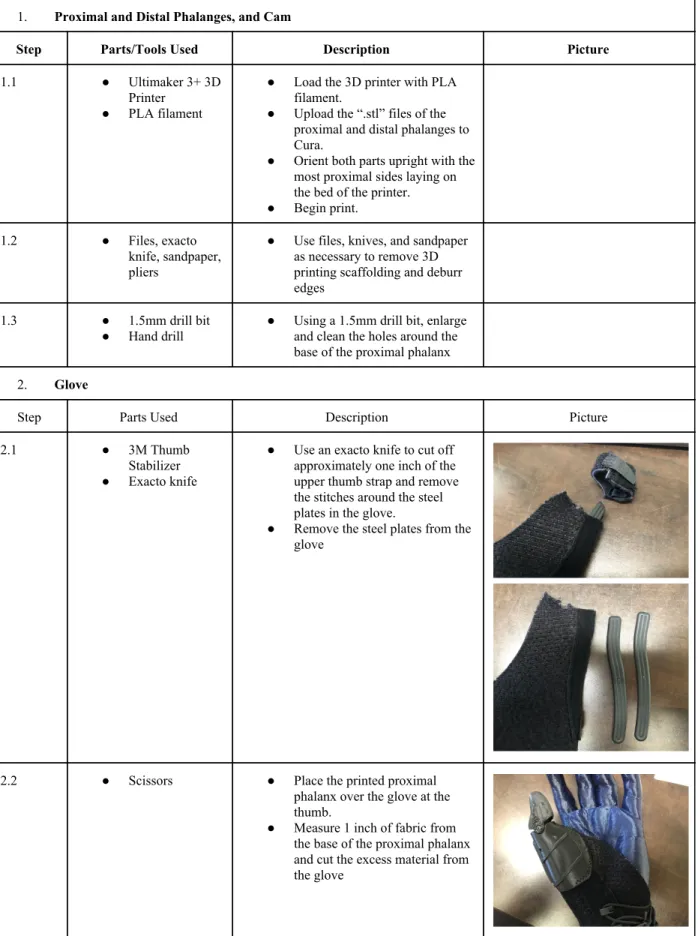
1. Proximal and Distal Phalanges, and Cam
Step Parts/Tools Used Description Picture
1.1 ● Ultimaker 3+ 3D Printer
● PLA filament
● Load the 3D printer with PLA filament.
● Upload the “.stl” files of the proximal and distal phalanges to Cura.
● Orient both parts upright with the most proximal sides laying on the bed of the printer. ● Begin print.
1.2 ● Files, exacto knife, sandpaper, pliers
● Use files, knives, and sandpaper as necessary to remove 3D printing scaffolding and deburr edges
1.3 ● 1.5mm drill bit ● Hand drill
● Using a 1.5mm drill bit, enlarge and clean the holes around the base of the proximal phalanx 2. Glove
Step Parts Used Description Picture
2.1 ● 3M Thumb
Stabilizer ● Exacto knife
● Use an exacto knife to cut off approximately one inch of the upper thumb strap and remove the stitches around the steel plates in the glove.
● Remove the steel plates from the glove
2.2 ● Scissors ● Place the printed proximal phalanx over the glove at the thumb.
3. Axle
3.1 ● Lathe
● Dowel Pin ● 1.6mm Drill bit ● Chamfer bit
● Note: Follow all shop safety protocols
● Install the dowel pin on the lathe. ● Cut the dowel pin to length. ● Use the tailstock and a 1.6mm
drill bit to drill a blind hole 8 mm deep into the dowel pin. ● Use a chamfer bit to lightly
deburr the hole.
● Repeat on the opposite side of the dowel pin.
3.2 ● M2x0.4 Tap Set ● Using a set of M2x0.4 taps, tap both holes 6mm deep
3.3 ● Clean tapped holes of the dowel
pin with compressed air and shop towels.
● Degrease with warm soap and water. Dry thoroughly. 4. BOA Fixture
4.1 ● Boa S2-S Dial Closure System
● Unscrew the top screw using a T-6 Torx Screwdriver. ● Remove the top piece.
● Remove the outer white locking dial.
● Remove the opaque circular piece that houses the wire by pushing through from the bottom of the device.
same orientation as the original wire.
4.2 ● Repeat the previous steps in
Table 11: MPI Assembly
Step Parts Used Description Picture
1. ● Wire
● Proximal phalanx
● Thread the loose end of the wire through the hole on the dorsal side of the proximal phalanx
2. ● Wire
● Cam
3. ● Distal Phalanx (Left Side)
● Cam
● Install the cam with the wire to the left half of the distal phalanx
4. ● Distal Phalanx (right side) ● Torsion spring ● Axle
● Shims
● Place the right side of the distal phalanx on the left side of the distal phalanx
● Place the torsion spring on the axle and seat on each leg to their respective anchoring points on the inside of the proximal and distal phalanges
● Align the distal phalanx with the proximal phalanx
● Line up the shims along the proximal anchoring holes ● Insert the axle
6. ● Glove
● Proximal phalanx
● Place the proximal phalanx over the remaining thumb portion of the glove cut from Manufacturing step 2.2
7. ● Size 5 ball-point sewing needle ● Stretch thread
● Using the sewing needle and thread, sew the proximal phalanx to the glove using a cross-stitch pattern as shown
8. ● Sew the BOA fixture to the base
of the glove
9. ● Confirm that the thumb is under
Table 12. Bill of Materials Part
Number Product Number Part Name Task Quantity Vendor
1. PLA 3D Printing Filament Prosthetic Thumb 1.0 in3 Innovation Sandbox
2. Loo’s and Company Medical Grade Wire Wire-Driven Mechanism 3 Ft
Donation from Loo’s and Co. 3. B074N5CMPG Stretch Thread Thumb Attachment 10 Yd Amazon
4. 6620K221 Stainless Steel Stock Internal Cam 1 McMaster-Carr
5. 90145A475 Dowel Pin Joint/Axle 1 McMaster-Carr
6. 9287K271 Torsion Spring Joint/Axle 1 McMaster-Carr
7. 90910A921 Screw Joint/Axle 2 McMaster-Carr
8. 98126A011 Shim Joint/Axle 2 McMaster-Carr
9. Futuro Deluxe Thumb Stabilizer Wrist Attachment 1 Target
16.0 Test Protocols
Figure 17 below shows the network diagram for all testing activities.
Also seen below in Table 13 is the pert chart for all testing. The pert chart numbers relate directly to the steps taken in the network diagram. Testing will be performed on Cal Poly San Luis Obispo’s campus. Testing preparation locations include the biomedical engineering senior design class room (192-329). Testing locations include the biomedical engineering lab (192-328) and the Cal Poly Machine Shop (aero hangar). Allison, Cale and Sahil can perform the testing preparation and hyper-extension testing on their own. Supervision from personnel is required in order to use the Instron Tester, and thus the Instron T.A. (Eric Dubofsky) will be supervising the compressive and tensile testing.
Compressive and tensile testing will be of the proximal and distal pieces on their own (not attached as they would be in full assembly). The distal piece will however be completed with all internal parts (such as cam, screws, shims, spring, etc.). The hyper-extension test will consist of the full prototype, with proximal and distal pieces fully attached to one another, connected by sewing mechanisms to the thumb stabilizer and with wire running through the assembly.
The testing criteria for the tensile test is 100 lbs +/- 5 lbs. If the test fails, we will either use a higher rated fishing line or look into using a stronger wire.
The testing criteria for the compression test is 100 lbs +/- 10 lbs. If the test fails, we will look into using a resin printer with Dr. Laiho.
Table 13. Pert Chart for Testing Activities.
Network Diagram Step
Task Name Date Time Lab Space Personnel Equipment Materials
1 3D print proximal phalanges - 9 samples
02/02/20 By 12 P.M. Innovation Sandbox Innovation Sandbox employees Ultimaker 3+ Extended 3D Printer PLA
2 3D print distal phalanges - 9 samples
02/02/20 By 12 P.M. Innovation Sandbox Innovation Sandbox employees Ultimaker 3+ Extended 3D Printer PLA
3 Cut 100 lb rated fishing line (12 inches) - 5 samples
02/04/20 By 4 P.M.
192-329 N/A Scissors PowerPro fishing line (100 lb)
4 Cut 40 lb rated fishing line (24 inches) - 12 samples
02/04/20 By 4 P.M.
192-329 N/A Scissors PowerPro fishing line
(40 lb)
5 Manufacture 1 axle, drill holes in 1 distal and 1 proximal piece for torsion spring, and cut the 100 lb rated fishing line
02/04/20 By 4 P.M.
Aero Hangar N/A Hand drill, lathe, tap set, scissors
PLA, PowerPro fishing line (100 lb), stainless steel stock
6 Manufacture entire assembly - 1 prosthetic
02/07/20 By 4 P.M.
192-329 N/A screwdriver , needle Proximal and distal phalange, internal cam, torsion spring, shams, screws, thread, thumb stabilizer, 100 lb PowerPro
7 Perform compression testing
02/11/20 12 P.M. 192-328 Eric Dubofsky (Instron TA)
Instron Tester - compressive plates
6 PLA proximal phalanges, 6 PLA distal phalanges, 12 40 lb rated fishing line
8 Perform tensile testing 02/11/20 12 P.M. 192-328 Eric Dubofsky (Instron TA)
Instron Tester - tensile grips
5 100 lb rated fishing line samples
9 Perform
hyper-extension testing
02/13/20 12 P.M. Aero Hangar N/A Vice - soft jaws, 5 lb weights
Completed prosthetic design
10 Redesign/reprint design if fails to meet criteria
02/20/20 12 P.M. Innovation Sandbox
N/A Ultimater 3+ Extended 3D Printer
PLA, or change of material?
11 Final date for testing/redesigning
16.1 Tensile Testing
Tensile testing will be performed in the Biomedical Engineering Materials Lab located in the Engineering IV building (192-328). In order to perform the tests, we will need to undergo training by the lab instructor as well as be supervised by him for the entire duration of using the Instron Tester. We do predict the wire during tensile testing to withstand 100 pounds of force, because that is what the fishing line has been rated by the manufacturer.
The Instron will be tested using a load 5 cm/s and the failure condition is until failure. The Instron only goes to a force of 500 N (112.4 lbs), and so if the wire does not fail before then, the test will stop at 500 N to prevent damage to the Instron tester. The test will succeed if the fishing wire can withstand the force of the rated pound test (100 lbs). Testing Criteria: All five individual trials need to pass in order for tensile testing to be considered as passing.
Figure 18. Instron Tester for Tensile Testing.
Power Pro Braid Fishing Line
1. Turn on and calibrate Instron Tester 2. Measure and record line dimensions
3. Load test samples and measure length between grips 4. Zero gauge length, balance the load, and run the tensile test 5. Repeat for 5 samples
Figure 19. Power Pro Braid Fishing Line.
16.2 Compression Testing
Compression testing will be performed in the Biomedical Engineering Materials Lab located in the Engineering IV building (192-328). In order to perform the test, we will need to undergo training by the lab instructor as well as be supervised by him for the entire duration of using the Instron Tester. In order to secure the proximal piece, we will be using the fishing wire to secure the piece to the bottom compressive plate. The fishing wire will be wrapped through the piece (using the holes cut out of the piece for the threading for the attachment to the wrist strap), then tied around the bottom of the bottom compressive plate. This will ensure that the proximal piece will not slide off the plate once contact has been made.
We will be testing until failure or up to 500 N (maximum load rate for the Instron tester). We expect the proximal piece to not fail, but we do expect the proximal piece to fail. Human bone of the femur can withstand forces up to 4,000 N before breaking. This is approximately 900 lbs of force. No material we choose will have the strength to match human bone, and so therefore we are only going to test up to a fraction of that. We want to test the proximal and distal pieces up to 100 lbs of force on the Instron compression test. If it can withstand that force, it should be good for our purposes. Testing Criteria: All three individual trials of the specific test run need to pass in order for compression testing to be considered as passing for that particular test.
Proximal and Distal PLA Phalanges
1. Exchange tensile Grips for compressive plates 2. Turn on and calibrate Instron Tester
3. Turn on materials tester and computer 4. Load necessary software
5. Measure all samples 6. Load proximal phalanx
a. Use fishing line to attach to bottom compressive plate b. Measure support span length
7. Calibrate and start the experiment 8. Repeat test 3 times per phalange
a. 2 orientations: horizontal along both axes
i. See Figures 27, 29 & 31 below for orientation 1 of the proximal piece ii. See Figures 33, 35 & 37 below for orientation 2 of the proximal piece b. 6 total tests
9. Repeat step 6 through 8 with distal phalange a. 6 total tests
i. See Figure 39 below for orientation 1 of the distal piece ii. See Figure 43 below for orientation 2 of the distal piece
16.3 Attached Segments in Hyper-Extension
The hyperextension test will be done in the Cal Poly Machine Shop - Aero Hangar. There is not any special requirements needed to perform this test, other than obtain a red/yellow tag to have access to the hanger (which all team members have completed as of December 2, 2019).
Testing will be completed until failure, or until 15 lbs, whichever comes first. Testing Criteria: The individual trial needs to pass in order for hyper-extension testing to be considered as passing.
Hyper-extension
1. Secure the prosthetic to the 3D printed hand model
2. Secure hand model with prosthetic in vice with soft jaws in pronated orientation a. See Figures 56 & 57 below for orientation
3. Hang weights off of the distal phalanx of the prosthetic in one pound increments, until failure
a. To complete our testing, we used a bucket, and filled it in increments of 15 oz of water (15.34 oz = 1 lb)
16.4 Water Testing
In order to complete this testing, we will be 3D printing two prosthetic thumbs, and coating one prosthetic with XTC-3D, a high performance 3D print coating. Both parts will be soaked in a water bath for 30 minutes, and the structural integrity will be compared between the two parts.
17.0 Testing Data and Analysis
17.1 Tensile Testing
Initial tensile testing was conducted on February 6, 2020 in 192-328 at 12:00 P.M.. Three testing attempts were conducted, and all three tests failed.
We measured and cut the 100 lb rated fishing line to be 6 inches, and made 5 samples. For the first round of testing, we secured the fishing line between the tensile grips, and ran the first test. However, as seen in Figure 23, the stress concentration was too high and the fishing line snapped just below the tensile grips. We then attempted to secure the fishing line by taking off the tensile grips, and tying the line around the pins that secure the grips into place, as seen in Figure 25. However, this test also failed due to the fact that the knot slipped. We tied it with a fisherman's knot, and the double uni knot (which is the best knot for our specific fishing line), and both tests failed at around 20 lbs due to the knot slipping. Finally, we removed the pins and tied the wire around the holes in the instron, however this test also failed. The internal edges were too sharp and cut the wire during the test, and so we need a new method in order to proceed with tensile testing.
Figure 22 & 23. Tensile testing 02/06/20, attempt 1.
Figure 25. Tensile testing 02/06/20, attempt 2.
17.11 Conclusion:
Figure 27. Tensile Testing, 02/06/20
All tensile testing failed.
The knot in the wire could not withstand a great force, as seen in Figure 27. The loads varied greatly as the knots slipped, and therefore all testing was inaccurate and therefore failed. Because of this, we are going to change materials to Loo’s and Company medical grade wire, as noted in our detailed design II section. This wire was given to Andrew as a free sample at a medical device convention in Pomona. We have also received the testing documents for the wire, and have decided to move forward with it. If we have time next quarter and the resources to purchase more wire, we will perform our own tests, however we will not be able to do so before March 17.
17.2 Compression Testing
Initial compression testing was conducted on February 20, 2020 in 192-328 at 12:30 P.M.
could still withstand a load of 500 N.
Figure 30 & 31. Proximal compression testing 02/20/20, orientation 1, attempt 2.
The proximal pieces were then tested in another direction; pressure from the upper compressive plate was applied to the outer portion of the proximal piece. They were also secured using extra fishing line, and tied securely to the bottom compressive plate. The first test was run, and the part failed at 70 N along the support material, as seen in Figure 35. The second test was run and the part failed at 170 N. As seen in Figure 37, the inner portion of part shattered. Finally, the third test was run, and the part had a minor crack at 47 N, another crack at 100 N, but still withstood compression until the load maxed out at 500 N.
Figure 36 & 37. Proximal compression testing 02/20/20, orientation 2, attempt 2.
Figure 38 & 39. Proximal compression testing 02/20/20, orientation 2, attempt 3.
seen in Figure 41, and none had any defects. When we attempted to run the test in the second orientation (with the compressive plate putting pressure on the top of the distal piece), the parts slipped. We will need to retest the pieces once the set screws are able to hold the parts together.
Figure 40. Distal compression testing 02/20/20, orientation 1.
Figure 42. Distal compression testing 02/20/20, orientation 2, attempt 1.
Figure 43. Distal compression testing 02/20/20, orientation 2, attempt 1.
The second round of distal compression testing was conducted on February 26, 2020 in 192-328 at 12:00 P.M.
Figure 44 & 45. Distal compression testing 02/26/20, orientation 2, attempt 1.
Figure 48 & 49. Distal compression testing 02/26/20, orientation 2, attempt 3.
17.21 Conclusion:
Proximal Pieces:
Figure 51. Proximal Compression Testing for Orientation 2, 02/20/20.
Proximal testing in orientation 1 and orientation 2 failed.
Distal Pieces:
Figure 52. Distal Compression Testing for Orientation 1, 02/20/20.
Figure 54. Distal Compression Testing for Orientation 2, 02/26/20
Distal testing in orientation 1 was a success and distal testing in orientation 2 failed.
Orientation 1 (force from the side) succeeded. The parts were able to withstand a force of 500 N without failing. There were no cracks noticeable, and the parts retained their structure as seen in Figure 41 above. Figure 52 represents the Load Vs. Extension for the distal pieces in orientation 1. It is seen that as the instron compression plates extended and the piece was compressed, there were no dips indicating any cracks in the material, and all three tests passed the test as they made it to 500 N.
Orientation 2 (force from the top) failed. In the first test, it was the internal components such as the set screw that caused the part to fail. The internal parts came out and so the distal piece was not intact and able to withstand 500 N. In the second and third test, the two halves of the distal piece and internal parts stayed intact, but the PLA material was cracked. Figure 54 shows numerous cracks that the second and third test experiences. There were numerous cracks (which are shown as dips in the graph), which can be seen in Figures 46 and 48.
The patient will most likely not experience a force of 500 N directly on the top of the distal piece, and so we were expecting the test to fail. We are planning on changing materials, and so we are hoping that next quarter the stronger 3D printed material will be able to withstand a higher force, without cracking.
17.3 Hyper-Extension Testing
The test was conducted by attaching the 3D printed hand model to a block of wood, and securing the prosthetic assembly over top of the hand/wood. The hand was secured horizontally in soft jaws of a vice, as seen in Figure 55 and 56. A bucket (measured at 14.6 g) was secured to the prosthetic using extra of the fishing line, as seen in Figure 58. The bucket was secured along the axis of rotation between the proximal and distal pieces, and 16 oz of water were slowly poured into the bucket.
The part failed at 13 lbs (1 lb of the bucket, and 12 additions of 16 oz of water). The part failed due to a crack in the material. We were expecting the stitching holding the proximal piece to the glove, or the hinge to fail. However, we are reprinting our final product that we will deliver to our patient in a stronger material.