Engineering of two-photon spatial quantum correlations behind a double slit
W. H. Peeters, J. J. Renema, and M. P. van Exter
Leiden Institute of Physics, Leiden University, P.O. Box 9504, 2300 RA Leiden, The Netherlands 共Received 23 December 2008; revised manuscript received 18 February 2009; published 16 April 2009兲
This paper demonstrates the engineering of spatially entangled two-photon states behind a double slit by tailoring the incident pure two-photon state. We experimentally characterize many different two-photon states by measuring their complete two-photon interference patterns in the far field of the double slit. Spatial en-tanglement right behind the double slit can reside in either the modulus or the phase of the two-photon field. The balance between these two types of entanglement is fully controlled by experimentally utilizing the phase-front curvatures of the pump beam and the phase-matching profile. We project either a far-field image or a magnified near-field image of the two-photon source onto the double slit. Our theoretical analysis shows how the two-photon interference pattern behind the double slit effectively acts as a phase-sensitive probe of the incident two-photon field profile. We thus present phase-sensitive measurements of the generated two-photon field profile probed in an image plane of the two-photon source.
DOI:10.1103/PhysRevA.79.043817 PACS number共s兲: 42.50.Dv, 42.25.Hz, 03.67.Bg
I. INTRODUCTION
Two photons are spatially entangled if their spatial de-grees of freedom, residing in the phase space of transverse position and transverse momentum, are quantum correlated. This form of entanglement can be easily generated via the nonlinear process of spontaneous parametric down-conversion共SPDC兲, where a single pump photon splits into a pair of down-converted photons关1,2兴. Spatial quantum cor-relations between two photons have played a pivotal role in many landmark experiments on fourth-order spatial interfer-ence 关3,4兴, ghost imaging and ghost interference 关1,5–7兴, quantum lithography 关8,9兴, and orbital angular-momentum entanglement 关10,11兴. Other experiments have addressed wave-particle complementarity 关12,13兴 and duality of one-photon and two-one-photon interferences 关13–16兴. Identification of spatial entanglement has been demonstrated via combined position-momentum measurements关17,18兴and a recent vio-lation of Bell inequalities 关19,20兴.
Spatial entanglement created via SPDC is of a high-dimensional form, and the spatial Schmidt modes are gener-ally quite complicated 关21兴. This spatial structure becomes less complicated by projecting each photon onto an array of holes. Behind a double slit, for example, the spatial entangle-ment exists between two transmitted photons of which each photon resides in a two-dimensional Hilbert space spanned by the upper slit and lower slit modes. Two-photon transmis-sion through a double slit has been demonstrated with both indistinguishable 关13,16兴 and distinguishable photons
关9,12,14,22–28兴. Extensions to high-dimensional forms of entanglement have been realized by using multislit apertures
关29–32兴. Methods for characterizing spatial entanglement be-hind a double slit have been demonstrated in Refs.
关25,26,28兴.
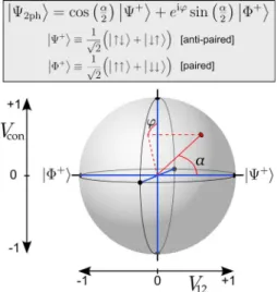
To set the stage for further discussion, we restrict our-selves to double-slit illumination schemes that obey mirror symmetry with respect to the optical axis. The transmitted two-photon state then takes the form
兩⌿2ph典= cos共␣/2兲
冉
兩↑ ↓典+兩↓ ↑典
冑
2冊
+eisin共␣/2兲
冉
兩↑ ↑典+兩↓ ↓典冑
2冊
, 共1兲where兩↑典and兩↓典represent transmissions through the upper slit and lower slit, respectively, and where␣andrepresent the state parameters. In principle, the above expression cov-ers a large variety of two-photon spatial quantum correla-tions behind a double slit.
Experiments so far have addressed only a subclass of all two-photon states represented by Eq. 共1兲. In many papers
关12–14,16,22,23,26,28–32兴, the double slit is positioned far away from the two-photon source where transmission is dominated by photons emerging from opposite slits so that 0ⱕ␣ⱕ12. Some of these papers have demonstrated how to control␣within this range关13,14,26,32兴. The opposite case, where both photons emerge from the same slit and␣=, has been realized by positioning the double slit very close to the two-photon source关9,27兴. This two-photon state plays a cen-tral role in the field of quantum lithography 关8兴. Until now, parameter ␣ has not been tuned within the range 12ⱕ␣ ⱕ. No attention has been paid to the experimental tuning of either, and most experiments seem to operate at⬇0. Yet, it is known that is highly relevant for the degree and type of spatial entanglement behind the double slit关26兴. One could, for example, consider a maximally entangled state at
␣==21where the entanglement resides in the phase rather than the modulus of the two-photon field right behind the double slit关33兴.
In this paper we demonstrate full control over the state parameters␣and. We achieve this by tailoring the imaging system in between the two-photon source and a single double slit. We switch between two imaging schemes: the crystal imaging scheme and the far-field 共ff兲imaging scheme. The crystal imaging scheme images 共a plane close to兲 the two-photon source onto the double slit. We will callthe curva-ture phase because we control this phase by utilizing the
phase-front curvatures of both the phase-matching profile and the pump beam profile. We characterize more than 30 different photon states by measuring their complete two-photon interference patterns in the far field of the double slit. Our theoretical analysis provides a direct connection be-tween the incident two-photon field profile and the state pa-rameters␣and. We show that the two-photon interference pattern behind the double slit effectively acts as a phase-sensitive probe of the incident two-photon field profile.
In our experiments, we use frequency degenerate SPDC in a periodically poled crystal where the signal and idler photons have the same polarization 共type-I SPDC兲. Hence, the obtained spatial quantum correlations exist between in-distinguishable photons. Our theoretical analysis, however, also applies to type-I SPDC in a uniform crystal and type-II SPDC in a periodically poled crystal. The analysis in this paper can thus also be used to engineer spatial quantum cor-relations between distinguishable photons.
The paper is organized as follows. The first theoretical part in Sec. IIdescribes how to engineer two-photon spatial quantum correlations behind the double slit. We describe how parameters␣anddepend on the incident two-photon field for the far-field and crystal imaging schemes. The sec-ond theoretical part in Sec.IIIdescribes one-photon and two-photon interferences behind the double slit. Section IV de-scribes the experimental apparatus. The experimental results can be found in Sec.V. The tuning of the two-photon state is illustrated with a number of measured two-photon interfer-ence patterns. The observed one-photon and two-photon in-terference patterns are compared with theory. The paper ends with a concluding section and a discussion on the possibility to tune two-photon spatial quantum correlations in a higher-dimensional Hilbert space. The Appendix discusses the va-lidity of our engineering model for various types of phase matching.
II. THEORY: TWO-PHOTON STATE ENGINEERING
A. Electromagnetic field behind double slit
The electromagnetic field behind a double slit is consid-ered. We assume the field to be the response to an incident quasimonochromatic two-photon field in a pure state. Trans-mission through the double slit can happen in three ways: either both photons come through, one photon comes through and the other one is blocked, or both photons are blocked. The density matrix of the electromagnetic field be-hind the double slit can thus be written as
ˆout=P0兩vac典具vac兩+P1ˆ1p+P2兩⌿2ph典具⌿2ph兩, 共2兲 where the first term represents vacuum, the second term rep-resents a mixed one-photon field 共one photon blocked兲, and the third term represents a pure two-photon field共both pho-tons transmitted兲. Equation共2兲emphasizes that experiments involving a single detector depend on both the one-photon component and the two-photon component.
We now direct our attention to the two-photon part兩⌿2ph典 of the transmitted state. Each photon can pass the double slit through either the upper or lower slit. We will denote these
two spatial modes by 兩↑典 and 兩↓典, respectively. The most general form of the two-photon part of the transmitted state can thus be written as
兩⌿2ph典=c1兩↑ ↑典+c2兩↑ ↓典+c3兩↓ ↑典+c4兩↓ ↓典, 共3兲 where the two Hilbert spaces belong to the two photons. We will now restrict ourselves to illumination setups that obey mirror symmetry with respect to the optical axis共see Fig.1兲. This symmetry implies thatc1=c4andc2=c3so that reversal of all arrows leaves the quantum state unaltered. With this restriction, the most general form of the two-photon state becomes
兩⌿2ph典= cos共␣/2兲
冉
兩↑ ↓典+兩↓ ↑典
冑
2冊
+eisin共␣/2兲
冉
兩↑ ↑典冑
+兩↓ ↓典2
冊
, 共4兲being a coherent superposition of two states that we will denote as antipairedand paired. In the antipaired state the two photons emerge from opposite slits. In the paired state the photons stick together and emerge from the same slit, being either the upper slit or the lower slit. Figure2 shows how the two-photon state can be depicted as a point on a two-particle Bloch sphere. We call the curvature phase because it depends on the phase-front curvature of the inci-dent two-photon field 共details in Secs.II B–II E兲.
The quantum state in Eq. 共4兲 represents a spatially en-tangled qubit pair, where the quantum information of each photonic qubit is encoded in its spatial properties. The degree of entanglement within a qubit pair is often quantified via the concurrence关34,35兴. For our case, the concurrence becomes
关26兴
C=
冑
1 − sin2共␣兲cos2共兲. 共5兲 On the two-qubit Bloch sphere of Fig. 2, the concurrence equals the distance from the point on the sphere to the ver-tical axis of the sphere. Quantum states on the horizontal equator 共=⫾/2兲 are maximally entangled regardless the value of␣. Quite remarkably, until now, hardly any attention has been paid to the experimental tuning of . This paper describes how to tune both ␣and.output ports of the beam splitter. The events in which the photons are reflected or transmitted in pairs are discarded. The experiments could fairly easily be extended to distin-guishable spatially entangled photons by using type-II SPDC in a periodically poled crystal共see Sec. II C兲.
B. Quantum state engineering
The main point of this paper is to demonstrate full control over the two-photon state behind the double slit as given by Eq.共4兲. We thus need to describe how␣anddepend on the incident quasimonochomatic pure two-photon state 兩⌿in典. The incident state is fully characterized by the two-photon field profile in the double-slit plane,
Aslits共x1,x2兲 ⬅ 具vac兩Eˆslits共+兲共x1兲Eˆslits共+兲共x2兲兩⌿in典. 共6兲
The operator Eˆslits共+兲共x兲 is the positive frequency electric field operator at transverse positionxin the double-slit plane. The two-photon field profile can be interpreted as the complex probability amplitude for simultaneous detection of one pho-ton at positionx1and the other photon at transverse position x2.
The two-photon field profile behind the double slit is just the sampled version of the incident two-photon field profile. We now assume that the slits are narrower than any spatial structure of the incident two-photon field profile. The trans-mitted two-photon state is then fully characterized by four complex amplitudes Aslits共⫾d,⫾d兲, where 2d is the slit separation. Because of the assumed mirror symmetry with respect to the optical axis we haveAslits共d,d兲=Aslits共−d, −d兲 and Aslits共d, −d兲=Aslits共−d,d兲. The first pair of two-photon amplitudes corresponds to paired photons, and the latter pair corresponds to antipaired photons. The coefficients of the
transmitted two-photon state in Eq. 共4兲 can thus be associ-ated with the incident two-photon field profile via
p⬅eitan
冉
␣ 2冊
=Aslits共d,d兲 Aslits共d,−d兲
. 共7兲
Here, we have defined p as the engineering parameter, which fully determines the transmitted two-photon state. Equation 共7兲 plays a central role in this paper because it describes the relationship between the incident two-photon field profile and the two-photon state behind the double slit.
C. Incident two-photon state
In this section we calculate the incident two-photon field profile for a two-photon state produced via the nonlinear process of SPDC. We consider frequency degenerate SPDC in the low-conversion regime with cw pumping along the positive z direction. The nonlinear crystal has two parallel planar facets in transverse xy planes separated by length L. We assume the divergence of the pump beam to be small such that the Rayleigh range is much larger than the crystal length. The pump photon has energy បp, and the signal and idler photons individually have approximately energy ប0=
1 2បp.
The phase-matching condition is essential for the precise form of the generated two-photon field profile. All equations derived below are based on noncritical type-I phase match-ing. Noncritical phase matching is generally applied in peri-odically poled crystals, and it means that the pump beam is orientated along a principal axis of the crystal. However, in the Appendix we show that our analysis also applies to non-critical type-II as well as non-critical type-I phase matching. In the latter case, the transverse walk-off distance of the pump should be much smaller than the pump beam diameter, which can be achieved by sufficiently loose focusing of the pump. The first step toward quantum state engineering is to cal-culate the two-photon field profile in the crystal-center plane. Following Ref.关36兴, we write for the momentum represen-tation of this two-photon field profile
A ˜
crys共q1,q2兲⬀E˜p共q1+q2兲˜共q1−q2兲, 共8兲 where the tilde symbol indicates the spatial Fourier trans-form, E˜p共q兲 is the momentum representation of the pump profile in the crystal-center plane, andq1,2are the transverse wave vectors of the two photons. The phase-matching profile is
˜共⌬q兲= sinc
冉
0+L兩⌬q兩2
8n00/c
冊
, 共9兲where sinc共x兲⬅sin共x兲/x,Lis the crystal length, andn0is the refractive index at the down-converted frequency. The 0 term accounts for the phase mismatch in forward direction.
The second step is to calculate the propagation from the crystal toward the double slit. The propagation of the two-photon field profile is described via
Aslits共x1,x2兲=
冕冕
Acrys共x⬘
,x⬙
兲h共x1,x⬘
兲h共x2,x⬙
兲dx⬘
dx⬙
,共10兲
whereh共x,x
⬘
兲is the共classical兲electric field propagator关37兴 from the crystal to the double slit at radial frequency0. The two-photon field profile remains factorized after propagation through any paraxialABCDlens system. Therefore, it is con-venient to think of the pump profile and the phase-matching profile as two separately propagating profiles. The two-photon field profile at any position z along the optical axis can thus be written asA共x1,x2;z兲⬀Ep,z
冉
x1+x2 2 ;z
冊
z冉
x1−x2
2 ;z
冊
, 共11兲where Ep,z共x;z兲 is the pump beam, z共x; 0兲⬅共x兲, and
z共x;z兲 is the phase-matching profile propagated at radial frequencypfrom the crystal center to positionz.
In the final step, we calculate the engineering parameterp from Eq. 共7兲. This calculation requires a one-dimensional description of the incident two-photon field profile. Below, we argue why it is allowed to single out one transverse di-mension in Eq.共11兲for the imaging schemes that we use. It may, however, not be concluded that a one-dimensional treatment is permitted for any general imaging scheme. The problem is that the phase-matching profile z共x;z兲does not factorize in two functions for the two transverse dimensions. The pump beam Ep,z共x;z兲, which we will assume to have a Gaussian profile, nicely factorizes in the two transverse di-rections.
In the far-field imaging scheme 关see Fig. 3共b兲兴, the slit separations that we use are much smaller than the phase-matching profile. The phase-phase-matching profile is thus approxi-mately constant in the region of the slits, and the two-photon
field scales with the pump profile. Singling out one dimen-sion is thus allowed for the far-field imaging scheme.
Our crystal imaging scheme 关see Fig.3共a兲兴is based on a mixed form of imaging, where lens 1 is a cylinder lens and lens 2 is a standard lens. This mixed form of imaging pro-duces only a crystal image in the direction perpendicular to the slits 共x direction兲, while it retains the far-field image in the direction parallel to the slits共ydirection兲. The size of the phase-matching profile along thexdirection is now similar to the slit separation, whereas the profile is much more exten-sive along theydirection. Furthermore, detection occurs via projection on round detection modes that are much smaller than the phase-matching profile along y direction in the double-slit plane 共2.1 mm versus 9.2 mm full width at half maximum intensity兲. The incident two-photon field profile is thus probed only around qy⯝0, and singling out the x di-mension is allowed.
D. Crystal imaging scheme
Our crystal imaging scheme can produce any two-photon state on the left hemisphere of the two-qubit Bloch sphere
共see Fig.2兲. The working principle is that the crystal is im-aged onto the double slit. For collinear phase matching
共兩0兩Ⰶ兲, the two photons leave the crystal from approxi-mately the same transverse position, and they arrive in the same way at the double slit关38兴. Hence, the two-photon state behind the double slit is dominated by the paired contribu-tion.
The crystal imaging scheme is shown in Fig. 3共a兲. The pump beam is weakly focused in the crystal-center plane. A plane close to the crystal center, i.e., within the Rayleigh range of the pump beam, is imaged onto the double slit with two lenses. The double slit is positioned in the back focal plane of the second lens; the corresponding object plane then coincides with the front focal plane of the first lens. The precise position of the object plane can now be tuned by moving the first lens longitudinally. We call this displace-ment the defocus distance ⌬z, where ⌬z= 0 if the object plane coincides with the crystal-center plane, and⌬z⬎0 for an increased distance between lens and crystal. The magni-fication of the imaging system isM⬅f2/f1, where f1 andf2 are the focal lengths of the first and the second lens, respec-tively. The slit separation is 2d.
The profile at the double slit is just the magnified version of the two-photon field profile in the object plane. The engi-neering parameter p, which completely determines the two-photon state behind the double slit via Eq.共7兲, becomes
p= A
冉
+dM, +d
M ;⌬z
冊
A
冉
+d M,−d M ;⌬z
冊
, 共12兲
whereA共x1,x2;z兲is the two-photon field profile of Eq.共11兲. Note that the object plane inside the crystal has actually moved over a distancen0⌬z. For convenience, we have used the propagation length ⌬zinstead of n0⌬z. This choice im-plies that A共x1,x2;z兲 must be treated as a two-photon field FIG. 3.共Color online兲Two schemes for quantum state
profile that has propagated over a distance z through an imaginary medium with refractive indexn= 1.
It is important to realize that the phase-matching profile
z共x;⌬z兲is much narrower than the pump profileEp,z共x;⌬z兲. As a consequence,d/M is much smaller than the waist of the pump beam in the relevant range of operation. Therefore, we can approximate the engineering parameter via
p= Ep,z
冉
dM;⌬z
冊
z共0;⌬z兲Ep,z共0;⌬z兲z
冉
d M;⌬z冊
⬇ z共0;⌬z兲
z
冉
d M;⌬z冊
. 共13兲
The argument and the absolute value ofp are determined by the phase-front curvature of z共x;⌬z兲 and amplitude varia-tions ofz共x;⌬z兲, respectively.
By using the expression for the phase-matching profile in Eq. 共9兲, we find the explicit expression
p=
冕
sinc共0+x2兲exp共−ibx2兲dx
冕
sinc共0+x2兲exp共−ibx2−iax兲dx, 共14兲
where sinc共x兲⬅sin共x兲/xand0 is the phase mismatch. The dimensionless parameters
a⬅ 2d
M
冑
Lc/共n0p兲, 共15兲
b⬅ ⌬z
L/共2n0兲, 共16兲 are the scaled slit separation and the scaled defocus distance, respectively. The two-photon state behind the double slit can be engineered by tailoring parameters a and b. Unfortu-nately, there is no simple analytic expression for the integrals in Eq.共14兲.
We can gain physical intuition for the influence ofaandb on parameterp by considering two general properties of the phase-matching profile z共x;z兲. First, the phase front of
z共x;z兲 is flat at the crystal center. This flatness causes pa-rameter p to be real valued for⌬z= 0 making the curvature phase = 0. Second, 兩p兩⬎1 at any ⌬z, as the maximum of
z共x;z兲stays at the optical axis during propagation. Numeri-cal evaluations show that 98% of the left hemisphere of the two-qubit Bloch sphere is covered by varyinga苸关0 , 8兴and b苸关−6 , 6兴. These evaluations also show that the coverage can be brought arbitrarily close to 100% for larger ranges of a andb.
E. Far-field imaging scheme
Our far-field imaging scheme can produce any two-photon state on the right-hand hemisphere of the two-qubit Bloch sphere 共see Fig.2兲. The working principle is that the far field of the crystal is imaged onto the double slit. The photons propagate with approximate opposite transverse mo-menta, so the photons arrive at approximate opposite
trans-verse positions in the double-slit plane. Hence, the two-photon state behind the double slit is dominated by the antipaired contribution.
The far-field imaging scheme is shown in Fig.3共b兲. The crystal is pumped with a weakly focused Gaussian beam with divergencepdefined viaE˜p共p/c兲⬀exp共−2/p
2兲 . The waist of the pump beam lies at a distance s in front of the crystal center. The far field of the crystal is symmetrically imaged onto the double slit by a lens with focal length f2. The slit separation is 2d.
It is important to realize that the far-field pump profile E
˜
p共q兲 is much narrower than the far-field phase-matching profile˜共q兲. As a consequence,d/f2is much smaller than the divergence of the phase-matching profile in the relevant range of operation. Therefore, the engineering parameter p can be approximated via
p= E ˜
p
冉
dpf2c
冊
˜共0兲
E ˜
p共0兲˜
冉
dpf2c
冊
⬇
E ˜
p
冉
dpf2c
冊
E ˜
p共0兲
, 共17兲
where the first equality is found by combining Eqs.共7兲,共8兲, and共10兲.
Insertion of the described pump profile yields the explicit expression
p= exp
冋
−冉
d f2p冊
2
冉
1 + iszR
冊
册
, 共18兲 where zR⬅2c/共p2
p兲 is the Rayleigh range of the pump beam. From this expression it is clear that any two-photon state with兩p兩⬍1 can be produced by tailoring the divergence of the pump beam p and its waist location s. These photon states lie on the right-hand hemisphere of the two-qubit Bloch sphere in Fig.2.
III. THEORY: INTERFERENCE BEHIND THE DOUBLE SLIT
A. State determination by two-photon interference
This section describes how we analyze the engineered two-photon state. We show that the two-photon interference pattern in the far field of the double slit serves as a finger-print of the quantum state described by Eq. 共4兲. Figure 1 shows the geometry of the detection setup. The far field of the double slit is formed in the back focal plane of a lens with focal length f. The two photons are probabilistically separated by a beam splitter 共see Sec. II A兲. Two detectors are positioned in the far-field planes formed in the two output ports of the beam splitter.
In the limit of narrow slits, the coincidence count rate in the far field of the double slit becomes关26兴
and ប0 is the energy of each photon. The coefficients are given by
Vdiff= cos2共␣/2兲, 共20兲
Vsum= sin2共␣/2兲, 共21兲
Vcon= sin共␣兲cos共兲, 共22兲 where we call Vsum the visibility in the sum of coordinates andVdiffthe visibility in the difference of coordinates. Coef-ficient Vcon relates to the fringe pattern in the single count rate conditioned on transmission of the second photon through the double slit. Therefore, we call Vcon the condi-tional one-photon visibility. Note that Vconis allowed to be-come negative and that this sign has a clear and measurable physical meaning. It is just for convenience that we incorpo-rate the sign of sin共␣兲cos共兲in what we call the conditional one-photon visibility.
The visibilities in the sum and difference of coordinates obey Vdiff+Vsum= 1. It is convenient to remove this redun-dancy and use only one quantity. Therefore, we define
V12⬅Vdiff−Vsum= cos共␣兲 共23兲 as the two-photon visibility difference. The interference pat-tern of Eq. 共19兲 is now determined by just two quantities beingV12andVcon.
The far-field two-photon interference pattern serves as a fingerprint of the two-qubit state. State parameter␣is deter-mined byV12= cos共␣兲 and state parameter兩兩 is then deter-mined byVcon= sin共␣兲cos共兲. The two-qubit Bloch sphere in Fig. 2 graphically connects these visibilities to the two-photon state: the in-plane horizontal coordinate isV12and the vertical coordinate isVcon. The sign of, indicating whether the state is on the front or rear side of the sphere, cannot be determined from the two-photon interference pattern. This sign, however, has limited physical meaning as the two-photon interference pattern, anywhere behind the double slit, is invariant under sign reversal of.
The experimental visibilities can easily be expressed in terms of the engineering parameter p, which characterizes the two-photon state behind the double slit via Eq. 共7兲. By combining Eqs.共7兲,共22兲, and共23兲, we find
V12= 1 −兩p兩 2
1 +兩p兩2, 共24兲
Vcon= p+pⴱ
1 +兩p兩2, 共25兲
enabling us to explicitly predict the outcome of the experi-ments based on the calculated parameterp.
B. Interpretation of the two-qubit Bloch sphere
The two-qubit Bloch sphere in Fig. 2 is a graphical rep-resentation of a pure two-qubit state that is restricted to the indicated linear superposition of two Bell states. All possible two-photon states on this sphere share a common Schmidt basis关26,39兴. These Schmidt states are located on the north
and south poles of the sphere, being 兩+典兩+典 and 兩−典兩−典, respectively, where 兩⫾典⬅冑12共兩↑典⫾兩↓典兲. The concurrenceC is thus directly related to the vertical coordinate Vconon the sphere. By combining Eqs. 共5兲and共22兲we find关26兴
C=
冑
1 −Vcon2 . 共26兲 The physical interpretation of Eq.共26兲is simple. If the pho-ton pair is strongly entangled 共C⯝1兲, the spatial state of each individual photon is necessarily mixed and cannot pro-duce a strong interference pattern on its own 共Vcon⯝0兲. In the opposite case of an approximately nonentangled state共C⯝0兲, the state of each individual photon is almost pure and produces strong interference 共Vcon⯝1兲.
The sphere provides a clear graphical interpretation of a well-known complementarity relation between V12 andVcon. By combining Eqs. 共22兲 and 共23兲 it is easily shown that
关40,41兴
V122 +Vcon2 ⱕ1 共27兲 orV122 ⱕC2. The stronger the entanglement, the larger兩V12兩is allowed to become. The absolute two-photon visibility dif-ference兩V12兩determines the correlation strength of the trans-verse positions of the photons right behind the double slit. Absence of this type of correlation, however, doesnotimply absence of entanglement because the entanglement could also reside in the phase rather than the modules of the two-photon field profile关33兴. Inequality共27兲becomes an equality for two-photon states with zero curvature phase共= 0兲.
The two-qubit Bloch sphere also suggests the existence of a third visibility,
Vp⬅sin共␣兲sin共兲=
−i共p−pⴱ兲
1 +兩p兩2 , 共28兲 being the coordinate along the “out of paper” direction. To-gether withV12andVcon, this third coordinate forms an exact complementarity relation
V122 +Vp 2
=C2. 共29兲
In the fully entangled case, whereC= 1 and Vcon= 0, a pro-jective measurement on photon A provides all quantum in-formation on photon B. The basis in which this quantum information is obtained depends on the character of the en-tanglement. AtV12=⫾1 andVp= 0, a projection of photon A in the slit basis兩↑典,兩↓典 provides full “which path” informa-tion on photon B. AtV12= 0 andVp=⫾1, photon A must be projected onto the states兩↑典⫾i兩↓典to obtain which path in-formation on photon B. It is yet unclear how to experimen-tally determine the third coordinateVp.
C. One-photon interference
on the one-photon part. The electromagnetic field behind the double slit is often even dominated by the one-photon part, i.e., P1⬎P2in Eq.共2兲.
For symmetric double-slit illumination, the intensity pro-file in the far-field plane of the double slit共see Fig.1兲is of the form
I共x兲⬀1 +Vunccos共兲, 共30兲 where the interslit phase difference relates to the detector positionxvia= 2d0x/fc. Equation共30兲implicitly defines the unconditional one-photon visibility Vunc. The second-order correlation function at the slits determinesVuncvia关42兴
Vunc=
G共1兲共d,−d兲
G共1兲共d,d兲 . 共31兲 The outcome of this equation is real valued due to the as-sumed illumination symmetry of the setup. Like the condi-tional one-photon visibility, we have defined the uncondi-tional one-photon visibility such that it can become negative. To calculate Vunc, we need the second-order correlation function in the plane of the double slit. The second-order correlation function in a transverse plane can be calculated via 关43兴
G共1兲共x1,x2;z兲⬀
冕
Aⴱ共x1,x;z兲A共x2,x;z兲dx, 共32兲 where A共x1,x2;z兲⬅具vac兩Eˆ共+兲共x1;z兲Eˆ共+兲共x2;z兲兩⌿in典 is the two-photon field profile and 兩⌿in典is a pure monochromatic two-photon state associated with light propagating along the optical axis. Equation 共32兲 has a broader range of validity than an alternative method based on the Van Cittert-Zernike theorem 关15兴. The latter theorem can only be used beyond the Rayleigh range of the photon source, and the two-photon source should be sufficiently spatially incoherent. The validity of Eq.共32兲 is retained close to the two-photon source even for partially coherent 共realistic兲 two-photon sources.As a first case, we calculateVuncfor the crystal imaging scheme that is treated in Sec.II Dand shown in Fig.3共a兲. By combining the generated two-photon field in Eqs.共8兲and共9兲, the propagation to the double slit关Eq. 共10兲兴, and the formu-las for the unconditional one-photon visibility in Eqs. 共31兲 and共32兲, we find
Vunc,cr=
冕
sinc2共0+x2兲exp共iax兲dx
冕
sinc2共0+x2兲dx, 共33兲
where sinc共x兲⬅sin共x兲/xanda is the共dimensionless兲scaled slit separation defined in Eq.共15兲. Again, we have assumed the pump profile to be much wider than the phase-matching profile. Unfortunately, there is no simple analytic expression for the integrals in Eq.共33兲.
As a second case, we consider the far-field imaging scheme that is treated in Sec.II Eand shown in Fig.3共b兲. By combining Eqs.共8兲,共10兲,共31兲, and 共32兲we find
Vunc,ff= exp
冋
−1 2冉
d f2p
冊
2
冉
1 +s2
zR
2
冊
册
, 共34兲 where 2d is the slit separation, p is the pump divergence, andzR⬅2c/共p2
p兲is the Rayleigh range of the pump beam. Again, we have assumed the far-field phase-matching profile to be much wider than the far-field pump profile. For this far-field imaging case, Eq.共34兲can also be obtained via the Van Cittert-Zernike theorem.
D. Duality between unconditional one-photon interference and two-photon interference
The relationship between unconditional one-photon inter-ference and 共conditional兲two-photon interference was stud-ied earlier in Refs. 关13–16兴. Saleh et al. 关15兴 theoretically pointed out that there exists a profound duality between the two phenomena if far-field imaging is applied. In this sec-tion, we show how this duality manifests itself in our model. We find new duality relations that apply to our far-field im-aging scheme, and we point out that the precise form of the duality relations strongly depends on the applied imaging scheme.
We consider far-field imaging关see Fig.3共b兲兴with a pump beam that is loosely focused in the crystal-center plane
共s= 0兲. For this specific imaging scheme we find that p=Vunc,ff2 by comparing engineering parameter p in Eq.共18兲 withVuncin Eq.共34兲. After convertingpinto the two-photon visibilities via Eqs. 共24兲 and 共25兲, we directly find duality relations
V12=
1 −Vunc,ff4
1 +Vunc,ff4 , 共35兲
Vcon=
2Vunc,ff2
1 +Vunc,ff4 , 共36兲 which strictly correspond to the specified imaging geometry. Equations 共35兲and共36兲 describe how the unconditional in-tensity pattern serves as a fingerprint of the two-photon state. In other imaging geometries, the duality relations become generally different or might even be multivalued. For ex-ample, the duality between V12 andVunc,ffwas reported dif-ferently in Eq. 共3.16兲 in Ref. 关15兴 because the authors as-sumed a top-hat-shaped flat pump profile inside the crystal instead of a Gaussian-shaped flat pump profile. As another example, no one-to-one duality relations exist for the crystal imaging scheme关see Fig.3共a兲兴. If crystal imaging is applied, some values ofVuncindividually correspond to multiple val-ues of V12 andVcon共see Fig.6兲.
IV. EXPERIMENTAL APPARATUS
A. General information
ex-plained in Secs. II Dand II E. The technical details of the apparatus are given in Secs.IV BandIV C.
B. Experimental apparatus in front of double slit
Photon pairs are generated via collinear spontaneous para-metric down-conversion 共SPDC兲 in a periodically poled KTiOPO4 共PPKTP兲 crystal. The conversion is such that pump, signal, and idler waves have the same linear polariza-tion. We pump the crystal with a continuous-wave y-polarized Gaussian beam propagating along thezdirection
共laser: Kr+, 200 mW at 413.1 nm兲. We operate in the quasi-monochromatic limit by applying detection behind narrow-band spectral filters共⌬= 5 nm at 826.2 nm兲. The crystallo-graphic x axis of the PPKTP is oriented along z direction
共pump direction兲 and the crystallographicz axis is oriented along the y direction 共poling direction兲. The crystal is L = 5.09 mm long, 1 mm thick inydirection, and 2 mm wide inxdirection. The pump beam is absorbed behind the crystal by a GaP wafer that is antireflection coated for 826 nm.
It is important to know the phase mismatch0because it strongly affects the engineering parameter p in the crystal imaging scheme 关see Eq. 共14兲兴. For our 5-mm-long crystal, the temperature dependence of the phase mismatch is mea-sured to be T0= 1.059 ° C−1关44兴. The phase-match tempera-ture is found to be T0=共60.39⫾0.04兲 ° C from measure-ments of the temperature-dependent spectrum of the SPDC light in forward direction. All double-slit experiments are performed at a temperature T=共60.70⫾0.01兲° C corre-sponding to a phase mismatch of0= 0.33⫾0.05.
We illuminate the symmetric and centered double slit either with a centered far-field image of the source using an f-f imaging system共far-field imaging scheme兲or a centered magnified image of the crystal by adding an extra cylinder lens 共crystal imaging scheme兲. The double slit is positioned at 80 cm from the crystal center, and the fixed far-field im-aging lens with focal length f2=共400⫾1兲 mm is positioned halfway. The removable cylinder lens with focal length f1
produces a sharp image of the crystal-center plane only in the direction perpendicular to the slits; the cylinder lens leaves the imaging in the parallel direction unaffected. The cylinder lens can be moved further away from the crystal by an amount that we call the defocus distance⌬z. They-oriented slits are created by wire electrical discharge machining in a phosphor bronze plate.
Some size parameters of the experimental apparatus are adjustable in order to be able to engineer many different two-photon states behind the double slit. In the crystal imag-ing scheme, we adjust the slit separation 2d, the focal length of the cylinder lens f1, and the defocus distance⌬z. In the far-field imaging scheme, we adjust the slit separation 2d, the pump divergencep, and the distance from the pump waist to the crystal centers.
We have used six double-slit apertures with slit separa-tions of 兵313, 510, 600, 758, 950, 1400其 m, all values with ⫾15 m uncertainty. The corresponding slit widths are
兵138, 150, 193, 135, 235, 225其 m. We used three different cylinder lenses with focal lengths of 12.7, 19.0, and 25.4 mm, all values with⫾2% uncertainty. The defocus distance is varied between −0.20 and 3.30 mm. The null position of ⌬zcorresponds to the point where the front focal plane co-incides with the crystal center. This position is calibrated to a precision of ⫾0.04 mm by reflecting a reference beam, which is backwardly focused in the primary focal plane of the cylinder lens on the front and rear crystal facets共reversed autocollimation兲. For the far-field imaging experiments with s= 0, we used three different pump divergences, 0.73, 1.31, and 2.27 mrad, all values with 10% uncertainty. Some mea-surements have been performed with pump waists in front of the crystal such thats⫽0.
C. Experimental apparatus behind double slit
The two photons behind the double slit are probabilisti-cally separated with a beam splitter behind the double slit. The events where the photons are both reflected or both transmitted are discarded 共see Sec. II A兲. A lens with focal length f= 400 mm is positioned between the double slit and the beam splitter. The lens images the far field of the double slit onto two intermediate detection planes in the two output ports of the beam splitter.
Detection occurs via projection onto the mode profiles of two single-mode fibers. In the double-slit plane, the centered Gaussian detection modes have 共loose兲 waist diameters of 2.1 mm for each mode 共full widths at half maximum inten-sity兲. Correspondingly, the detection modes have waist diam-eters of 70 m in the intermediate detection planes 共full widths at half maximum intensity兲. The finite size of the detection modes does not affect the observed fringe visibility because the field projection is phase sensitive, and the period of the two-photon fringe pattern is at least 240 m which is more than three times larger than the width of the detection modes. The two-photon interference pattern is measured by scanning two computer-controlled detection stages trans-versely. Each detection stage comprises the fiber tip and an objective with an effective focal length of 8 mm. The detec-tion modes thus only move in the far field of the double slit, FIG. 4. 共Color online兲 Schematic representation of the
while their intensity profiles remain fixed in the double-slit plane.
The single-mode fibers are coupled to single-photon counting modules 共Perkin-Elmer SPCM-AQR-14-FC兲. Si-multaneous photon detections are registered by coincidence electronics. The applied gate time of our pulse correlator is
g=共1.73⫾0.01兲 ns. If two photons from different photon pairs are detected within this time window, it is fallaciously registered as a coincidence count. The count rate of these so-calledaccidental counts is
Rac=R1R2g, 共37兲 whereR1andR2are the raw single count rates in detector 1 and detector 2, respectively. The “real” coincidence count rate is obtained by subtracting the accidental count rate from the measured coincidence count rate. In our experiments, the accidental count rate typically accounts for about 10%–45% of the rawly measured coincidence count rate. The photon count integration time is 1 s for each pixel of the measured two-photon interference patterns.
V. EXPERIMENTAL RESULTS
A. General information
In this section we demonstrate the engineering of many different photon states behind the double slit. Each photon state is characterized via a measurement of the two-photon interference pattern in the far field of the double slit. The interference patterns provide the conditional one-photon visibilityVconand the two-photon visibility differenceV12for each two-photon state. The manner in which these visibilities relate to the engineered two-photon state is graphically indi-cated on the two-qubit Bloch sphere in Fig.2. The intensity fringe patterns are also recorded. These yield the
uncondi-tional one-photon visibilityVunc. The analysis and tuning of the two-photon interference pattern are discussed in Sec. V B. Quantitative comparison with theory is performed in Secs. V C–V F.
B. Analysis and tuning of two-photon interference patterns
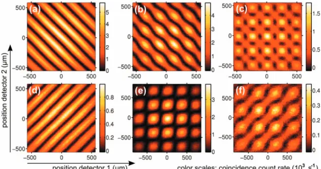
Six examples of measured two-photon interference patters are shown in Figs. 5共a兲–5共f兲. This selection covers a whole range of different double-slit imaging types. The upper row is measured with the crystal imaging scheme, and the lower row is measured with the far-field imaging scheme. The left column contains the two extreme cases where the slit sepa-ration is large compared to the coherence width of the down-converted light at the double slit. The central column is mea-sured with slit separations similar to the coherence width. The right-hand column is measured with a certain amount of defocusing, meaning that either⌬z⫽0 for the crystal imag-ing scheme or s⫽0 for the far-field imaging scheme.
The general form of the two-photon interference pattern, given by Eq. 共19兲, allows for an insightful interpretation of the fringe visibilities. The three visibilities—Vsum,Vdiff, and Vcon—become isolated after projections on the +45° diago-nal, the −45° diagodiago-nal, and the horizontal axis, respectively. Mathematically, these projections result in
R+45°共x1+x2兲⬀1 +Vsumcos
冉
x1+x2xs/2
冊
, 共38兲R−45°共x1−x2兲⬀1 +Vdiffcos
冉
x1−x2xs/2
冊
, 共39兲R0°共x1兲⬀1 +Vconcos
冉
x1wherexsis the fringe period for coherent light at the down-converted wavelength. In order not to deform the projection, it is important to select an integer number of fringe periods in the direction orthogonal to the projection axis. Each fringe pattern has been analyzed by fitting these three projections after including the effect of limited angular diffraction due to the finite slit width关26兴. The two-photon visibility difference is then found via its definition V12⬅Vdiff−Vsum. The sum Vdiff+Vsum= 1 is automatically obeyed if the experimental ap-paratus is aligned properly.
In the far-field imaging scheme, the two photons arrive at approximately opposite positions in the double-slit plane. Hence, two-photon transmission is dominated by the anti-paired two-photon component causing V12 to be positive. One quickly recognizes that the lower three interference pat-terns have positive V12 because the fringes projected on the −45° diagonal are more distinct than the fringes projected on the +45° diagonal. The extreme case, where the slit separa-tion is large compared to the pump divergence, is shown in Fig. 5共d兲. This two-photon state is almost completely anti-paired as we findV12=共96⫾1兲%. Paired two-photon trans-mission can be increased by increasing the pump divergence relative to the slit separation. Such an increase has been ap-plied to situation 共e兲 where the fringe orientation is hardly visible andV12=共25⫾3兲%.
The tuning ofV12in the crystal imaging scheme is analo-gous. The photons arrive at approximately equal positions in the double-slit plane. Hence, two-photon transmission is dominated by the paired two-photon amplitude, causing V12 to be negative. The extreme case is shown in Fig.5共a兲, where the slit separation is large compared to the size of the mag-nified phase-matching profile. The corresponding two-photon state is almost completely paired and we determine V12= −共96⫾1兲%. The antipaired two-photon transmission can be enhanced by increasing the magnification of the im-aging system or reducing the slit separation. In situation共b兲, the slit separation is reduced to about the size of the magnified phase-matching profile z共
x
M;⌬z= 0兲 resulting in V12= −共89⫾1兲%.
The conditional one-photon visibility can be interpreted as the fringe visibility produced by each individual photon of the transmitted pair. By projecting the two-photon fringe tern on the horizontal axis, it is easily recognized that pat-terns 共a兲and共d兲 haveVcon⬇0. The conditional one-photon visibility is close to 100% for pattern共e兲. Patterns共b兲and共f兲 feature Vcon⬍0 because each of these two patterns has a minimum in the center of the image. The other four patterns have centered maxima corresponding toVconⱖ0. Calibration of detector positions x1,2= 0 is performed via measurements of the coincidence count rate without double slit. Patterns共b兲 and共f兲 correspond to two-photon states on the lower hemi-sphere of the two-qubit Bloch hemi-sphere in Fig.2.
Patterns共c兲and共f兲are special because they have nonzero curvature phase. Such configurations can only be achieved with defocused two-photon imaging, meaning that⌬z⫽0 for crystal imaging ors⫽0 for far-field imaging. The character-izing feature of defocusing is the emergence of a checker-boardlike pattern. This changes the topology of the interfer-ence pattern by splitting the dark curves of zero coincidinterfer-ences into patches of low coincidence counts. A checkerboardlike
pattern reduces the conditional one-photon visibility so that the two-photon state is brought closer to the horizontal equa-tor of the two-qubit Bloch sphere.
The degree of entanglement is directly related to the con-ditional one-photon visibility via Eq. 共26兲. Maximum en-tanglement manifests itself asVcon= 0 and a total absence of separability of the interference pattern in horizontal and ver-tical directions. Patterns共a兲and共d兲, on one hand, correspond to maximally entangled states as these have zero conditional one-photon visibility. Pattern 共e兲, on the other hand, corre-sponds to an almost nonentangled two-photon state as the pattern almost factorizes.
The curvature phase is highly relevant for the degree of entanglement. Pattern 共c兲, for example, has V12= −0.14⫾0.01 which is rather close to zero, and, at the same time, it is strongly entangled with a concurrence of C= 0.906⫾0.008. Such combination is only possible if the curvature phase is nonzero. The curvature phase is
兩兩=共64.7⫾1.0兲° for pattern 共c兲. The entanglement has al-most fully “migrated” from the modulus to the phase of the two-photon field profile right behind the double slit关33兴.
C. Crystal imaging at= 0
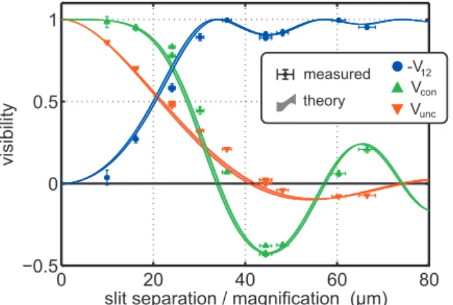
This section presents the experimental results obtained with the crystal imaging scheme of Fig.3共a兲with zero defo-cus ⌬z= 0. We only vary the reduced slit separation 2d/M, whereM is the magnification of the imaging system. Work-ing at zero defocus, we expect to engineer two-photon states with zero curvature phase = 0. Figure 6 depicts the mea-sured visibilities V12, Vcon, and Vunc versus the reduced slit separation. The vertical error bars are based on the internal errors and scan resolutions of the two-photon interference patterns. The theoretical curves forV12andVconare based on Eqs. 共24兲,共25兲, and 共14兲. The theoretical curve forVuncis a plot of Eq. 共33兲. We observe good agreement between ex-periment and theory.
The three plots in Fig.6contain a wealth of information. First of all, the shape of each curve is directly related to the phase-matching profile of the periodically poled crystal. Our theoretical curves are based on the sinc-shaped phase-matching profile in momentum representation 关see Eq.共9兲兴. The observed agreement between experiment and theory means that the phase-matching profile is indeed sinc shaped in its momentum representation. Second, we observe that VconandVuncare negative for some values of the reduced slit separation. Negativity of these parameters means that we ob-serve minima instead of maxima in the centers of the mea-sured interference patterns. Finally, we observe thatVconand Vunc are different from each other. For the crystal imaging scheme, there is no one-to-one duality relation between these visibilities like there is for the far-field imaging scheme关see Eq. 共36兲兴. Interestingly, the experiments prove thatVunc can be zero, while the two-photon state behind the double slit is not maximally entangled for the same geometry 共Vcon⫽0兲.
is the phase mismatch 0. It was determined to be 0 = 0.33⫾0.05 from measurements of the SPDC spectrum. However, if we would plot the theoretical visibilities using
0= 0.65 we would observe excellent agreement between theory and measured visibilities. This means that a system-atic error of only 0.3 ° C in the phase-matching temperature would already explain the observed small systematic differ-ence between experiment and theory.
In Fig.7the engineered two-photon states are depicted as points in a square with V12 and Vcon along the axes. The points on the left half plane correspond to the measurements from the crystal imaging scheme. The measurements are in excellent agreement with the complementarity relation V122 +Vcon2 = 1 that is predicted for two-photon states with zero curvature phase= 0.
Previously, of the two-photon states withV12⬍0, only the fully paired two-photon state had been prepared by position-ing a double slit with large slit separation very close to the crystal 关9,27,32兴. We now demonstrate that the fully paired photon state can also be prepared by imaging the two-photon source onto a double slit. To the best of our knowl-edge, two-photon states corresponding to −1⬍V12⬍0 or Vcon⬍0 have never been prepared before. Our experiments with the crystal imaging scheme are phase-sensitive mea-surements of the two-photon field structure in an image plane of the crystal center.
D. Far-field imaging at= 0
We present the experimental results obtained with the far-field imaging scheme of Fig. 3共b兲with zero defocus共s= 0兲, where we expect to engineer two-photon states with zero curvature phase= 0. We only vary the relative slit separa-tion 2d/共2f2d兲, where 2f2d is the diameter of the pump beam in the double-slit plane. Figure8depicts the measured
visibilities V12,Vcon, andVuncversus the relative slit separa-tion. The horizontal error bars are determined by the 10% uncertainty in the pump divergence. The vertical error bars are based on the internal error and scan resolution of the two-photon interference patterns. The theoretical curves for V12 and Vcon are based on Eqs. 共24兲, 共25兲, and 共18兲. The theoretical curve forVuncis a plot of Eq.共34兲.
We observe excellent agreement between theory and the measured visibilities. For small slit separations we observe that the two-photon visibility difference V12⬇0, meaning that the moduli of the paths of the two photons are hardly correlated. We also observe that these states are approxi-mately nonentangled becauseVcon⬇1. For larger slit separa-tions V12 approaches 1, indicating that the concurrence FIG. 6. 共Color兲Measured visibilities obtained with the crystal
imaging scheme of Fig.3共a兲at⌬z= 0 for various reduced slit sepa-rations 2d/M. The theoretical two-photon visibilitiesV12andVcon are calculated via Eqs.共24兲and共25兲for the two-photon state with engineering parameterpfrom Eq.共14兲. The theoretical curve for the unconditional one-photon visibilityVuncis calculated via Eq.共33兲. The uncertainty in the theoretical curves, indicated by finite curve widths, originates from the uncertainty in the phase mismatch 0 = 0.33⫾0.05. No fit parameters are used for the theoretical curves.
FIG. 7. 共Color online兲Measured visibilities of engineered two-photon states with zero curvature phase= 0. The two-photon states on the left side are prepared with the crystal imaging scheme in Fig. 4共a兲at⌬z= 0. The two-photon states on the right are prepared with the far-field imaging scheme in Fig. 4共b兲 at s= 0. The annotated measurements correspond to fringe patterns in Fig.5. The exterior of the circle is forbidden by the complementarity relation Vcon2 +V122 ⱕ1. Figure2graphically indicates howVconandV12relate to the engineered two-photon state.
increases, andVcongoes down. Furthermore, we observe that the conditional and the unconditional one-photon visibilities are different from each other. Interesting is the observation that the curves forVconandVunccross each other. This cross-ing has neither been predicted nor observed before. It is in agreement with the duality relation of Eq.共36兲.
Each engineered two-photon state can be depicted as a point in a square with V12 and Vcon along the axes. This representation is visualized in Fig.7, where the points on the right half plane correspond to our measurements from the far-field imaging scheme. The measurements are in excellent agreement with the complementarity relation V122 +Vcon2 = 1 that is predicted for two-photon states with zero curvature phase = 0. Previously, an experimental demonstration of complementarity was performed by Abouraddy et al. 关13兴, albeit with less accuracy.
E. Crystal imaging at nonzero curvature phase
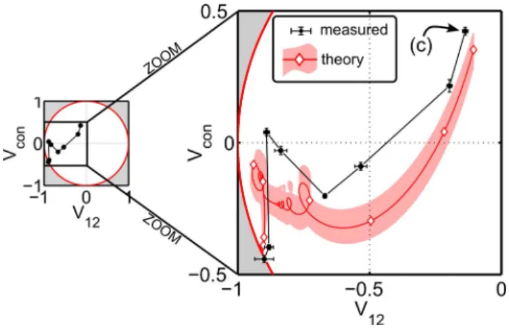
Two-photon states with nonzero curvature phase have been engineered with the crystal imaging scheme in Fig.3共a兲 at nonzero defocus distance⌬z⫽0. A plane slightly behind the crystal center is imaged onto the double slit. Due to the propagation away from the crystal-center plane, the phase-matching profilez共z;⌬z兲has developed a certain wave-front curvature. This wave-front curvature causes the curvature phase to become nonzero. The curvature phase is highly relevant for the two-photon interference pattern behind the double slit. The characterizing feature of two-photon states with 0⬍兩兩⬍ is that V122 +Vcon2 ⬍1, implying that these states are located in the interior of the complementarity circle. The curvature phase is also relevant for the degree of entanglement.
Figure9shows the two-photon visibilitiesV12andVconof eight two-photon states that are engineered with the crystal imaging scheme at increasing defocus distance ⌬z. For this series, we have used a reduced slit separation of 2d/M =共44.5⫾1.3兲 m and eight equidistant values of ⌬z. We observe that the two-photon state at ⌬z⬇0 has approxi-mately zero curvature phase, as this measurement lies on the complementarity circleV122 +Vcon2 = 1. For increasing defocus, we observe that the two-photon states obtain nonzero curva-ture phases, as their two-photon visibilities lie in the interior of the complementarity circle.
The theoretical curve, including its uncertainty region, is calculated from the engineering parameter p given by Eq.
共14兲. The visibilities V12 andVconare then derived via Eqs.
共24兲and共25兲. The wiggly nature of the theoretical curve in Fig.9originates from the Fresnel-type integrals in the equa-tion forp. We observe reasonable agreement between theory and experiment. All the more so, a strong resemblance is found when considering the relative orientation of two points within any pair of successive measurement points. This re-semblance is striking because these relative orientations are quite erratic while the defocus distance⌬zis increased over equidistant values.
The measurements in Fig. 9 are the first phase-sensitive measurements of the two-photon field structure in an image of a plane close to the crystal center, i.e., within the Rayleigh range of the phase-matching profilez共x;z兲.
F. Far-field imaging at nonzero curvature phase
Two-photon states with nonzero curvature phase have also been engineered with the far-field imaging scheme in Fig. 3共b兲 at s⫽0. The phase front of the pump beam in the double-slit plane is curved now because the pump waist is located in front of the nonlinear crystal. The wave-front cur-vature of the pump beam in the double-slit plane causes the curvature phase to become nonzero. States with nonzero curvature phase haveV122 +Vcon2 ⬍1 implying that such states are located in the interior of the complementarity circle. The curvature phase is relevant for the two-photon interference pattern as well as the degree of entanglement.
Figure 10shows the two-photon visibilities V12 andVcon of six two-photon states that are engineered with the far-field imaging scheme with s⫽0. We observe that the two-photon state behind the double slit has nonzero curvature phase as the states lie inside the complementarity circle. We also dem-onstrate that it is possible to reach the lower hemisphere of the two-qubit Bloch sphere 共Vcon⬍0 in Fig. 2兲 by altering the pump beam. Two-photon states on the lower hemisphere have never been prepared before.
VI. CONCLUSION
thatis highly relevant for the two-photon interference pat-tern as well as the degree of entanglement behind the double slit. State characterization is achieved by performing mea-surements of the complete two-photon interference pattern in the far field of the double slit.
The presented analysis of two-photon state engineering is complete for illumination systems within the following three restrictions. First, we consider illumination schemes and double slits that obey mirror symmetry around the optical axis 共see Sec. II A兲. Second, we assume slits that are nar-rower than the transverse coherence width of the illumina-tion共see Sec.II B兲. Third, the two-photon source is based on any type of SPDC in a periodically poled crystal or type-I SPDC in a uniform crystal provided that the transverse walk-off of the pump beam is negligible with respect to its width
共see Sec. II Cand Appendix兲.
For a symmetric setup and narrow slits, the two-photon state behind the double slit becomes a coherent superposition of a paired state, where the photons emerge form the same slit, and an antipaired state, where the photons appear from opposite slits. The relative phase between both contributions is the curvature phase . The absolute balance between the paired and antipaired components is described by state pa-rameter␣.
It is demonstrated how to engineer any two-photon state in this form. The paired two-photon component dominates if the crystal imaging scheme is used. The antipaired two-photon component dominates if the far field of the source is imaged onto the double slit. The precise balance between the paired and antipaired components is controlled by tailoring the magnification properties of these imaging systems. The curvature phase is fully controlled by utilizing the phase-front curvatures of the pump profile Ep,z共x;z兲 and phase-matching profilez共x;z兲. The phase-matching profile governs the engineered two-photon state in the crystal imaging scheme. The pump profile governs the engineered two-photon state in the far-field imaging scheme.
We have shown that the two-photon interference pattern in the far field of the double slit serves as a fingerprint of the
engineered two-photon state. The pattern directly yields the one-photon visibility Vcon and the two-photon visibility dif-ference V12. These visibilities conveniently relate to the po-sition on the two-qubit Bloch sphere that we have presented to graphically depict any engineered two-photon state. This sphere is also highly convenient to read off the concurrence. We have engineered and characterized more than 30 dif-ferent two-photon states. Good agreement between measure-ments and theory is observed. Two-photon states exhibiting strong curvature phase, states with Vcon⬍0, and states with −1⬍V12⬍0 have never been prepared before. Our experi-ments with the crystal imaging scheme are phase-sensitive measurements of the two-photon field structure in an image of a plane close to the crystal center, i.e., within the Rayleigh range of the phase-matching profilez共x;z兲.
Using the crystal imaging scheme, we have presented measurements of the unconditional one-photon visibilityVunc in an image plane of the crystal center. In the far-field imag-ing scheme, we have demonstrated the duality betweenVcon andVuncfor Gaussian pump profile that is loosely focused in the crystal-center plane. The experimental results are in agreement with theory.
VII. DISCUSSION: TUNING IN HIGH-DIMENSIONAL HILBERT SPACE
In this paper, the tuning range of the engineered two-photon states has been restricted to a two-dimensional Hil-bert space spanned by two out of four maximally entangled Bell states 关see Eq. 共4兲兴. However, spatially entangled two-photon states generated via SPDC allow for tuning in much higher-dimensional Hilbert space. We will now discuss some experimental tuning parameters that remained untouched in this paper.
The entire four-dimensional Hilbert space of Eq. 共3兲 be-comes accessible if one allows asymmetric illumination schemes with distinguishable photons. The coefficients c1 andc4become uncoupled by allowing asymmetric illumina-tion schemes. Such asymmetry could be achieved by apply-ing an asymmetric pump profile or by movapply-ing the double slit transversely to a noncentered position. The coefficients c2 andc3become uncoupled if one uses distinguishable photons in combination with an asymmetric illumination scheme. Distinguishable spatially entangled photons can be produced via type-II SPDC in a periodically poled crystal关7,24,27兴or by using two double-slit apertures positioned in the two out-put ports of a beam splitter. An experiment where c2= −c3 has been demonstrated in Ref. 关24兴 by placing birefringent crystals in front of the double slit.
One can also turn to multidimensionally entangled two-photon states by using multislit apertures 关29–32兴. To tune between different multidimensionally entangled states, one could use a variable pump profile based on a spatial light modulator. Another interesting tuning parameter is the temperature-dependent phase mismatch 0 of the periodi-cally poled crystal. The analysis in this paper may serve as a good starting point to make the extension to quantum state engineering of multidimensionally entangled two-photon states.
ACKNOWLEDGMENTS
We acknowledge stimulating discussions with J. P. Woer-dman, D. Bouwmeester, and E. F. C. Driessen. The research is supported by the Stichting voor Fundamenteel Onderzoek der Materie共FOM兲.
APPENDIX: VALIDITY OF VARIOUS PHASE-MATCHING GEOMETRIES
The theoretical analysis in this paper is based on noncriti-cal type-I phase matching共see Sec.II C兲. In this Appendix, however, we show that the analysis also applies to noncriti-cal type-II as well as critinoncriti-cal type-I phase matching. Noncriti-cal phase matching is generally applied in quasi-phase-matched processes, and critical phase matching is generally applied in uniform crystals.
We will first give expressions for the two-photon field profile in the crystal-center plane for various phase-matching geometries. We consider a nonlinear crystal with two parallel planar facets in transversexyplanes. For the critically
phase-matched cases treated below, the crystallographic optical axis lies in the positive yz plane. Following Refs. 关36兴and 关45兴 we use a generic quasimonochromatic expression for the two-photon field profile in the crystal-center plane.
A ˜
crys共q1,q2兲⬀˜Ep共q1+q2兲sinc
关
12L⌬kz共q1,q2兲
兴
, 共41兲 where sinc共x兲⬅sin共x兲/x, and the wave-vector mismatch⌬kz共q1,q2兲=kz共q1+q2,p,p兲−kz共q1,0,1兲 −kz共q2,0,2兲−共2⌳−1兲, 共42兲 wherekz共q,,兲is thezcomponent of the wave vector of a plane wave with transverse wave vector q, radial frequency
, and polarization. The fourth term between parentheses does not apply to uniform crystals; it only applies to periodi-cally poled crystals where ⌳ is the poling period. All other symbols are defined in Sec. II Cof the main text. Equation
共41兲is valid for any type of phase matching as it is based on a simple plane-wave expansion. The Taylor expansion of Eq.
共42兲up to second-order becomes approximately
⌬kz共q1,q2兲 ⬇C+
兩q−兩2 4n00/c
+
冦
0 for noncritical type I and type II −关q+兴y for critical type I 共e→oo兲
+12关q+−q−兴y for critical type II 共o→oe兲,
冧
共43兲
whereC is the wave-vector mismatch in the forward direc-tion, q⫾⬅q1⫾q2, n0 is the refractive index at the down-converted frequency, and is the walk-off angle for extraordinary-polarized light共⬎0 if directed away from the crystallographic optical axis兲. We have omitted the relatively small direction, frequency, and polarization dependencies of the refractive index in all second-order terms. We have also omitted the frequency dependence of the walk-off angle.
In the noncritically phase-matched case, above equations directly lead to Eqs. 共8兲 and 共9兲 describing the generated two-photon field profile in the main text of this paper. We therefore conclude that the analysis in this paper applies to all noncritically phase-matched SPDC processes. For non-critical type-II phase matching, one can easily add the polar-ization dependence of the refractive to the phase-matching profile in Eq. 共9兲 of the main text by substituting n0 for 2n1n2/共n1+n2兲, wheren1andn2are the refractive indices of the two down-converted photons.
For critical type-I phase matching, a linear term appears in the wave-vector mismatch in Eq. 共43兲. This linear term can be neglected if the pump beam is sufficiently loosely focused; loose focusing causes the momentum representation E
˜
p共q+兲 to become compact such that it over-rules the much broaderq+ dependence of⌬kz in Eq.共41兲. This criterion is
met if the walk-off term 12L关q+兴yin the argument of the sinc function is much smaller than a radian at a typical value of
关q+兴y= 2/wp, where wp is the width of the Gaussian pump beam in real space and 2/wpis the width of the pump beam in transverse momentum space. The loose-focusing criterion thus becomes LⰆwp for critical type-I phase matching, simply stating that the transverse walk-off distanceLmust be much smaller than the pump beam width. In Sec.II C, we have already assumed loose focusing 共Rayleigh range pumpⰇcrystal length兲in order to obtain simple expressions for the engineering parameters in Eqs. 共14兲 and 共18兲. The loose-focusing criterion LⰆwp for critical type-I phase matching is generally stronger.