Surveillance Camera System for Mobile Computing
Environments using an Active Zooming Camera and
MAC Address Tracking
Hideaki Goto
Information Synergy Center, Tohoku University, Aoba 6–3, Aramaki, Aoba-ku, Sendai, 980–8578 Japan.
E-mail: hgot@isc.tohoku.ac.jp
Abstract
Mobile computing environments using wireless networks and Ethernet jacks have become popular recently in universities, cafes, on the streets, etc. Although many of the network access systems are protected by user authentication, they are sometimes attacked by people who try to use the network illegally. It is difficult for network administrators to locate, track, and identify users in such a mobile environment because people travel from site to site. If a conventional, fixed surveillance camera is used for monitoring a big field, it cannot take pictures whose resolution is high enough for personal identification. To deal with these problems, we propose an intelligent surveillance camera system that utilizes an active camera for tracking and zooming into network users for better personal identification. The system is also equipped with a MAC address tracking mechanism that is useful for reducing video data to be recorded.
Keywords
: surveillance camera, wireless network, active camera, user tracking, MAC address tracking1
Introduction
In this paper, we introduce an application of object-tracking visual surveillance for securing mobile computing environments and propose a system architecture that is useful for locating, tracking, and identifying users.
Mobile computing environments using wireless net-works and Ethernet jacks have become popular recently in universities, companies, airports, ho-tels, cafes, on the streets, etc. Securing the net-works by some kinds of protection such as user authentication is very important in the mobile net-works, because they are sometimes attacked by people who try to use the network illegally [1]. We developed a user authentication method and made the program open to public as a free software named authipgate [2, 3]. This method has been successfully used in several sites in our university. Those who abuse the networks are not limited to malicious people. Even a legitimate user might unintentionally abuse the networks or commercial services. In a university, for example, we see some students and staff downloading too many electronic journal papers. This is often a violation of subscription condition. The university could be barred from subscription to journals if such incidents took place quite often. The university
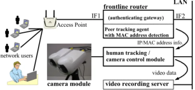
Figure 1: Mobile computing environment and user tracking.
has to know who are actually connecting their computers to the campus network.
In mobile computing environments, it is difficult for administrators to locate, track, and identify users. IP address is useless for identifying comput-ers (terminals) because people travel from site to site (figure 1). User ID is not so reliable because attackers would use stolen IDs or never attempt to login. To make host identification easier, we developed an agent program that enables network administrators to know the MAC (Media Access Control) addresses of remote hosts [4]. Examin-ing MAC addresses will help the administrators to find identical hosts, since every host connected to Ethernet has a unique MAC address. Although the MAC address may be forged by using special
tools, this method is still considered to be useful to deal with casual network crimes.
However, even a host identification cannot provide very important information associating the host with its real user. An attacker might be using a stolen hardware. Unfortunately, there is no online method for finding the actual person. Biometric identification has not been popular yet. One of the plausible solutions is to use surveillance cameras. Some problems related to surveillance camera ex-ist. The first problem is low resolution of video images. If a conventional fixed camera is used for monitoring a large room or a big outdoor field to find mobile users, it cannot take pictures whose resolution is high enough for personal identifica-tion. The resolution is still too low even with a high-resolution video camera. Deploying a lot of cameras is not always acceptable due to its high cost.
The second problem is the large amount of video data. Finding suspicious persons in a very long video sequence manually is a laborious work and is not practical. Investigation process should be automated as much as possible.
To deal with these problems, we have developed an intelligent surveillance camera system that uti-lizes an active camera for tracking and zooming into network users for better personal identifica-tion. The system is also equipped with a MAC address tracking mechanism that is useful for re-ducing the amount of video data to be recorded. This paper is organized as follows. In section 2, the outline of the system is given. In section 3, we propose a method for tracking multiple objects using a fixed camera and an active camera. In section 4, the MAC address tracking mechanism is discussed. Section 5 gives some experimental results, and section 6 concludes this paper.
2
Surveillance Camera System for
Mobile Computing Environments
The surveillance camera system proposed in this paper consists of four modules. Figure 2 shows the overview of the system.
The camera module has two video cameras, which monitor the activities of the mobile network users. One of them is a fixed camera for detecting the moving objects in a wide field of view. The camera zoom is set to its wide-end, i.e. zooming is not used. The other camera is an active camera with pan, tilt, and zoom capabilities. This camera is used for tracking and zooming into the objects. A peer tracking agent runs on the frontline router and monitors network activities. The frontline
Figure 2: Overview of the system.
router is the router which mobile computers are directly connected to. The agent finds IP/MAC address pairs and send the information to the human tracking / camera control module.
The human tracking / camera control module captures video signal from the fixed camera, detects and tracks moving objects (humans) in the video sequence, and control the active camera. This module caches some video frames and sends them to the video recording server only when some activities are detected in the wireless network or on the Ethernet jacks.
The video recording server records the video frames from the cameras for future investigations. This server has not yet been built into our system be-cause we were concentrating into the MAC address tracking and the object tracking.
3
Multiple Object Tracking using a
Fixed/Active Camera Pair
3.1
Selection of object detection method
An object detection method is needed for tracking humans. The following three major techniques are known.1. Background subtraction. 2. Frame difference. 3. Optical flow.
The frame difference and the optical flow have been used successfully in many applications where targets are moving fast enough. In our application, however, the system needs to detect nearly-static objects as well. In mobile computing environments, people are sitting on chairs or benches, standing at tables, or walking very slowly, while they are using their computers. We decided to use the background subtraction since the frame difference did not yield any good result in our experiments.
Methods based on the background subtraction per-form better in detecting static objects. However,
the background subtraction is less tolerant of the changes of illumination and backgrounds. A lot of improved methods using background estimation and update techniques have been proposed [5, 6, 7]. In our application, people may move chairs, tables, windows, and doors, and lighting condition may change. The system has to adapt to the back-ground changes within a few seconds. We em-ployed a background update method based on [5] that is rather simple and easy to tune. We made a minor improvement to the method to reduce faulty object detection.
3.2
Object detection
The video signal from the fixed camera is captured at 720×480 pixels in color and reduced to 360×240 pixels. The background image is estimated and updated by pixel-wise operations.
Letf(t) be the color vector of a pixel in the input image att-th frame. LetB(t) be the color vector of the pixel at the same place in the estimated back-ground image. The color difference δ(t) is mea-sured by Euclidean distance in RGB color space, andδ(t) forms a difference image.
δ(t) =|f(t)−B(t)| (1) The difference images for the last Int frames are kept in the memory.
Let tcurr denote the current frame (time). Let
δmax(tcurr) denote the maximum value of δ(t) within the latest Int frames. In the same way,
δmin(tcurr) denotes the minimum. Image stability is defined byS(tcurr) =δmax(tcurr)−δmin(tcurr). The image stability becomes almost zero if no mov-ing object exists or an object stays on the pixel for more than Int frames. The background image is updated by the following rule.
B(tcurr+1) =
B(tcurr) ifS(tcurr)< Ts f(tcurr) otherwise , (2) wheref(tcurr) is the image derived from the orig-inal images.
We saw many faulty objects where an object went across in the scene when the raw input image
f(tcurr) was used forf(tcurr). B(t) was replaced by the foreground object color in some places where the background color and the object color coincidentally became similar, and this caused a lot of scattered blobs in the estimated background. To reduce the noise, we used the average of the previous Int frames instead for f(tcurr). This technique delays the update of the background. The next step is to make an object map, which is a binary image of the same size as the input images.
Figure 3: Tracking multiple objects. All the pixels are set to zero at first. Each pixel is turned on if the color difference is greater than a threshold, i.e. δ(t)> Tobj. Then, the object map is reduced by 8×8-pixel blocks to help the following processings. If a block contains more than two ON-pixels, the block is labeled with object. Otherwise, the block is the background.
Connected components are found in the reduced object map after the dilation operation by 3× 3-pixel square structure element is applied. Bound-ing boxes of the connected components correspond to the objects detected.
3.3
Tracking of multiple objects
Figure 3 depicts the tracking process of multiple objects. The rectangles A1, B1, and C1correspond to the objects detected in the previous frame. The rectangles A2, B2, C2, and D2 correspond to the objects newly detected in the current frame. The tracking module has to find the best correspon-dences of these rectangles between the adjacent frames to track multiple objects.
We made a simple algorithm for the tracking. We do not need to care about overlapping objects since our task is a visual surveillance and the objects do not need to be separated. Two measures are used in the algorithm to find the closest rectangle pairs. The first measure is the overlap ratio defined by
Rovl(X1,X2) = (overlap area between X1 and X2) (area of X1)×(area of X2) ,
(3) where X1and X2are the rectangles of the previous frame and the current frame, respectively. The ratio is calculated for each rectangle. The rect-angles X1 and X2 are connected only when they have the largest overlap ratios from both sides. Thus, we have some separated chains of rectangles. Each chain represents the trace of an object under tracking.
In figure 3, for example, A1 and A2 are connected because A2has the largest ratio with A1 and vice versa. B1 and B2 are connected in the same way.
trace 1
t active cameratracking by
time shift trace 5 trace 4 trace 2 trace 3 t recording (end) (start) MAC4 MAC3 MAC2 MAC1 sw act t
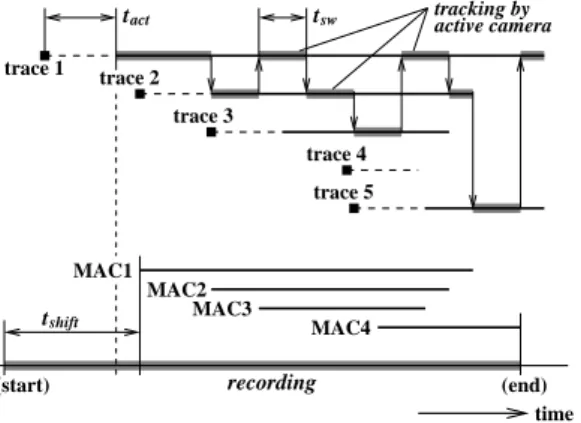
Figure 4: Camera and recording controls.
Although D2 has the largest ratio with A1, it is not connected to A1. In this case, a new trace is created for D2.
Some rectangles do not overlap each other because they are very small. Another measure is used for this case. We used the distance defined by dc(X1,X2) = (Euclidean distance between centroids of X1 and X2) . In figure 3, C2 is connected to C1 because the distance is the smallest from each other.
Some rectangles corresponding to an object may be missing for some frames. Every rectangle should be kept alive for about a second. When a rectan-gle does not have any follower for long time (one second), the corresponding trace is discarded.
3.4
Control of active zooming camera
The surveillance system has only one active cam-era, while the system are supposed to track multi-ple persons. The system needs to switch the target of the camera to catch as many events as possible. We used the round robin algorithm for the target switching. Figure 4 shows the timing chart of the camera control.After a switching interval tsw has passed, the tar-get is changed and the camera starts tracking the next trace, i.e. object. In figure 4, the trace 2 dis-appears during the tracking. The target switching occurs immediately in this case.
The object detection and the object tracking pro-cesses would produce some faulty traces due to the noise. The lifetimes of many of these traces are short as shown by the trace 4 in figure 4. We employed a mechanism to reduce the trackings of the faulty traces. The age of each trace, which represents the duration time from the creation of the trace, is evaluated. If the age of a trace has not reached tact, the trace is excluded from the candidates of the target switching.
The camera is directed toward the current rectan-gle in the trace. Let (xt, yt) be the coordinates of the centroid of the rectangle measured from the image center. The angles for the pan/tilt drives,
θpan andθtilt, are calculated as follows.
θpan = gh·xt+oh (4)
θtilt = gv·yt+ov , (5) wheregh andgv are the horizontal/vertical gains, and oh and ov are the horizontal/vertical offsets. The four parameters were found manually in our experiments. We are able to obtain zoomed video sequences that are acceptable as long as the objects are far enough from the camera module, although this angle calculation is rough.
3.5
Recording control
The timing chart of the recording control is also shown in figure 4. The video sequences are recorded only when any activity is detected by the fixed camera and any activity is found in the mobile network. Four MAC addresses are detected and informed to the camera control module in figure 4.
The video recording should start from the frame a few minutes (tshift) earlier than the first activity detection (MAC1 in this example), because the ad-ministrators would want to look at the very scenes when a suspect walks into the room, comes to a chair, and starts using a computer. The time shift can be made possible by the frame cache built into the camera control module.
4
MAC Address Tracking for Host
De-tection and Identification
4.1
Host detection by ARP table look-up
MAC (Media Access Control) address, as the name implies, is used for controlling the communication of Ethernet. When a host establishes an IP connec-tion with another host over Ethernet, both hosts have to know each other’s IP/MAC address pair. The MAC address is informed to other hosts by ARP (Address Resolution Protocol). Every net-work operating system, including UNIX and MS-Windows, has an ARP table in its kernel. We can know a computer is connected to the local network by looking into the ARP table.MAC address has been used not only for the origi-nal purpose but also for software’s license control, host identification, an alternative of user authen-tication in mobile networks, etc., because the ad-dress is unique in the world.
Due to the original purpose of it, MAC address does not propagate over a router. We needs a spe-cial program that collects IP/MAC address pairs and informs the data to the camera control mod-ule. The program should run on a router which the mobile computers are directly connected to as shown in figure 2.
4.2
MAC address tracking
The MAC address tracking is performed as follows. An agent program periodically examines the ARP table to detect changes of address entries. As soon as a computer is connected to the network and it starts communications over the frontline router, the MAC address of the computer is added to the ARP table. Thus, the agent program is able to detect a new computer and inform the camera con-trol module via the local area network that the new computer has just been connected. The agent pro-gram does need to pick up the MAC addresses only on the IF1 interface to avoid detecting neighboring hosts on the IF2 side.
A MAC address entry stays in the ARP table as long as it is periodically updated from the peer computer. When the computer is disconnected physically or stops all communications, the corre-sponding entry stays in the ARP table for a few minutes and is removed afterward. The agent pro-gram detects this change and informs the camera control module that the computer has been re-moved.
Unfortunately, it is impossible to know the exact times of the disconnections unless a special hard-ware is used. The network administrators have to be careful about the time lag when they analyze the recorded video sequences.
5
Experimental results
5.1
Implementation
We built a system using a PC, two cameras, and a wireless network system we had built earlier. The PC has a 2.6GHz Pentium 4 processor, 1.5GB memory, and an Ethernet interface. The Linux 2.4 operating system was used. We used SONY EVI-G20 for the active camera. The camera has fast pan/tilt drives and a 3X zoom lens. The zoom was set to the tele-end (3X), since there was no need to take pictures at lower resolution. The same model was used for the fixed camera as well. Its zoom was set to 1X. AF (auto focus) and AGC (auto gain control) were both turned on in the experiments. The video signal from the fixed camera was converted to DV (digital video) format by an
NTSC–DV converter and captured by the PC via IEEE1394 interface at 720 ×480 pixels, 10fps. The pan/tilt/zoom drives were controlled by the PC via serial interface.
The human tracking / camera control module was implemented by a multi-threaded program writ-ten in C++. The MAC address tracking module was implemented by a C program. We added the MAC address tracking feature to the Peer Tracking Agent trackpeer [4]. The program was run on the frontline router in the wireless network sys-tem. The program monitors the network activities and informs MAC address changes to the human tracking / camera control module via the UNIX’s syslog.
5.2
Performance evaluations
We tested the system using some scenes in our laboratory room. The timing parameter for background estimation was set to Int = 5(sec) (=50frames at 10fps). The switching interval was set to tsw = 3(sec). In many cases, the system could successfully detect multiple moving objects and take their high-resolution video images by the active camera.
We confirmed that the system can adapt to back-ground changes within almost ten seconds, which was longer than the theoretical timeInt= 5. This was due to the noise in the video sequences and some of the automated features of the camera such as auto focusing.
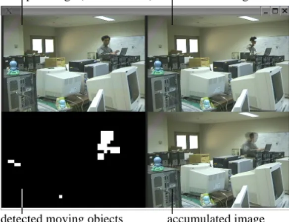
Figure 5 shows the monitor screen of the system with one of the test scenes. In this scene, a person came into the room, put a laptop computer on top of desktop computers, and began using the wireless network. The image of the person taken by the fixed camera was too small for personal identification. Two swinging toys were placed to test the object tracking and the target switching. The picture at the bottom right depicts the accu-mulated image, which is the mean of the past 50 frames. The picture at the bottom left shows the moving parts in the scene. All three objects were correctly detected.
The laptop computer and some parts of the human body were blended into the background as shown in figure 5. These ghost-like images will be detected as fake objects after the person and the laptop computer disappear from the scene. This phe-nomenon would not be a serious problem because the fake objects do not last long and the active camera will not be directed to the objects after one or two rounds of the target switching.
accumulated image detected moving objects
raw input image (fixed camera) estimated background
Figure 5: Monitor screen of the system.
(b) target 2 (a) target 1
(c) target 3
Figure 6: High-resolution images taken by the active camera.
Figure 6 shows the high-resolution images of the targets taken by the active camera. The resolution of these images is high enough for user (object) identification.
The video recording server has not been imple-mented yet. We manually examined the output data of the MAC address tracking module. The module was able to detect the changes of the ARP tables successfully and inform the IP/MAC ad-dress pairs to the PC on which the camera control module was running.
6
Conclusions
This paper has introduced an intelligent surveil-lance camera system for mobile computing envi-ronments. By combining a fixed camera and an ac-tive camera, the system can track multiple persons and take high-resolution video images. The system can provide video data that are more reliable for personal identification.
The amount of video data to be recorded is much lower than that of the other systems in which many
cameras are used. The video data can be further reduced by combining the network monitoring with the visual surveillance. The MAC address tracking method proposed in this paper can also provide some important information about the mobile com-puters. These features will greatly help network administrators to locate, track, and identify users. Our future work includes designing an advanced system that can control multiple camera modules and analyze data from multiple access points, developing an algorithm for automatic camera calibration, and implementing the video recording server.
7
Acknowledgements
This work was partially supported by the Strategic Information and Communications R&D Promotion Programme (SCOPE) of the Ministry of Internal Affairs and Communications in Japan.
References
[1] R. Beck : Dealing with Public Ethernet Jacks — Switches, Gateways, and Authentication. Proceedings of the 13th System Administration Conference (LISA’99), pp.149–154, 1999. [2] H. Goto, M. Mambo, and H. Shizuya : Secure
Access Ports with Authentication Using Inex-pensive Switches and the Secure Shell. Trans. IEICE (D-I), Vol.J84–D–I, No.10, pp.1502– 1505, 2001. (in Japanese)
[3] H. Goto : Simple Authenticating Gateway for Linux.
http://themes.freshmeat.net/projects /authipgate/ (as of Sep 12, 2005) [4] H. Goto : trackpeer: Peer Tracking Agent.
http://themes.freshmeat.net/projects /trackpeer/ (as of Sep 12, 2005)
[5] S. Nagaya, T. Miyatake, T. Fujita, W. Ito, and H. Ueda : Moving Object Detection by Time-Correlation-Based Background Judge-ment. Proceedings of ACCV’95, pp.717–721, 1995.
[6] M. Pic, L. Berthouze, and T. Kurita : Adaptive Background Estimation: Computing a Pixel-Wise Learning Rate from Local Confidence and Global Correlation Values. IEICE Trans. Inf.&Syst., Vol.E87–D, No.1, pp.50–57, 2004. [7] R. Cucchiara, M. Piccardi, and A. Prati :
Detecting Moving Objects, Ghosts, and Shad-ows in Video Streams. IEEE Trans. on PAMI, Vol.25, No.10, pp.1337–1342, 2003.