StoneGate How-To
Remote Firewall Deployment
StoneGate Firewall 3.0 and Management Center 3.5Table of Contents 2
Table of Contents
The Scenario . . . page 3
Adjusting the Access Rules and NAT rules . . . page 3
Defining Locations and Contact Addresses . . . page 5
The Scenario 3
The Scenario
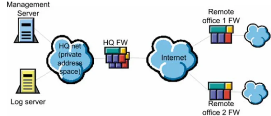
This document describes the steps needed to make the StoneGate’s internal systems communications work in an environment where a StoneGate Management Center at a headquarters (HQ) site, protected by a StoneGate firewall, is used to manage firewalls at remote office sites and to store any logs that are generated. This example scenario includes a commonly used setup where the Management Server and Log Server at the HQ site have private IP addresses, which the StoneGate firewall at the central site translates to public IP addresses for communications over the Internet.
Illustration 1: Example Scenario
The following changes are needed to allow system communications from the remote firewalls to the HQ site: • The Access rules of the firewall at the HQ site must be modified to allow the communications between the
Management Center Servers and the remote office firewalls. The pre-defined rules inherited from the Default Policy Template allow system communications that have the firewall itself as the source or destination.
• The NAT rules at the HQ site must be modified to translate the private IP addresses of the Management Server and the Log Server to public IP addresses for routing through the Internet.
• Locations and contact addresses must be defined to make the remote office firewalls aware of the translated IP addresses of the Management Server and the Log Server. Otherwise the firewalls will assume that the
components’ private IP addresses in the HQ network should be used and the communications will fail.
Adjusting the Access Rules and NAT rules
This section shows you the Access and NAT rules that are needed in the central HQ office firewall to allow the system communications from the remote office firewalls to the Management Center. There is no need to edit the policies of the remote office firewalls (because the Default Policy Template is in use and it does allow system communications that have the remote office firewalls themselves as the source or destination).
There are pre-defined Service elements for system communications. The Services needed in this example case are explained in the two tables below. A complete list of system communications is presented in the “StoneGate-Specific Ports” appendix included in all StoneGate user guides. The listed Service elements are available in the system by default. They are used in the Default Template Policy and in the example rules in this document to allow the system communications.
Adjusting the Access Rules and NAT rules 4
TABLE 1: System Communications Initiated by the Firewall
The communications detailed in Table 2 are connections initiated from the Management Server to the firewalls, and they concern only firewalls that have a fixed IP address. If the firewall has a dynamic IP address, connections are always initiated from the firewall to the Management Server as explained in the table above.
TABLE 2: System Communications from the Management Server to Firewalls
Illustration 2 below shows the Access rules that allow communications from the remote office firewalls to the Management Center. The Firewall elements are not used in the policy directly, but they are included in the Group element Remote FW control IPs. The remote office firewalls must use the public (translated) IP address of the Log Server and the Management Server, so the rules use a Host elements Management NAT and Log Server NAT to represent the public IP addresses instead of the Server elements, which contain the internal IP addresses.
Note – If the remote firewalls have a dynamic IP address, specific “Remote FW control IPs” groups can not be defined for the firewalls, because the IP addresses of the firewalls are unknown. Instead, the Source must be ANY or “Not Internal”, or If the DHCP IP address range of the remote firewalls (assigned by the internet operator) is known, also these ranges can be used in the policy.
Illustration 2: Example Access Rules
Service Name TCP Port Description
SG-log 3020 Logs, alerts, and firewall statistics and (from firewall version 3.0 onwards) status information from the firewall to the Log Server. SG-init 3021 Initial contact from the engine to the Management Server to establish a trust relationship. SG-log-backup 3023 Backup channel for sending information on engine status from the engine to the Management Server if the Log Server is unavailable.
SG-dynamic-control 8906 All other communications between a firewall with a dynamic IP address and the Management Server. Always initiated from the firewall. Not used by firewalls with a fixed IP address.
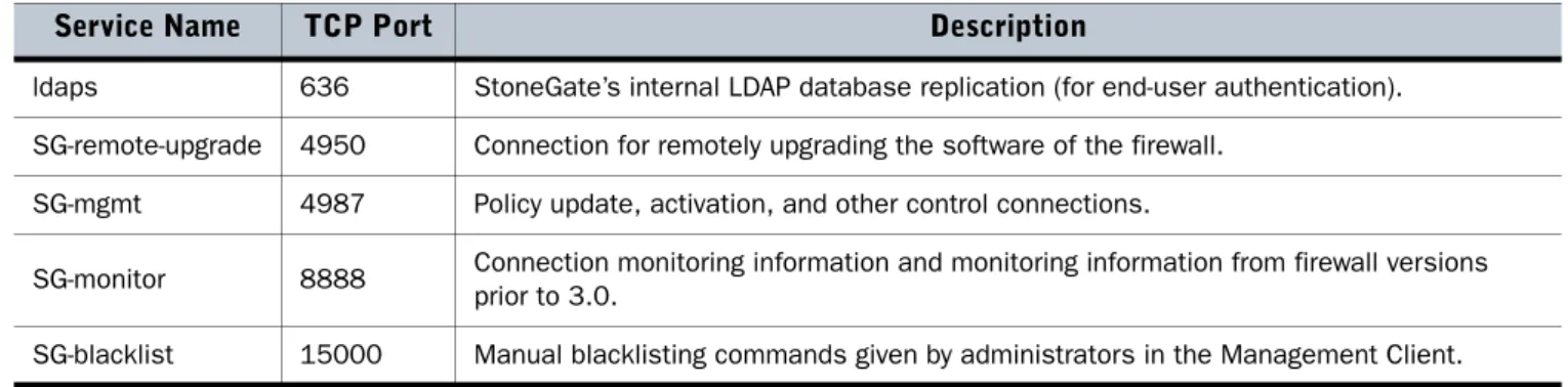
Service Name TCP Port Description
ldaps 636 StoneGate’s internal LDAP database replication (for end-user authentication). SG-remote-upgrade 4950 Connection for remotely upgrading the software of the firewall.
SG-mgmt 4987 Policy update, activation, and other control connections.
SG-monitor 8888 Connection monitoring information and monitoring information from firewall versions prior to 3.0.
Defining Locations and Contact Addresses 5
Illustration 3 below shows the NAT rules that translate the internal IP address of the Management Server and Log Server. The Log Server does not initiate connections to the external network in the example configuration, so there is only one rule for the Log Server.
Naturally, the first rule that translates connections initiated by the Management Server would not be necessary either if the remote office firewalls had dynamic IP addresses. In that case, all communications would be initiated by the firewalls.
Illustration 3: Example NAT Rules
Defining Locations and Contact Addresses
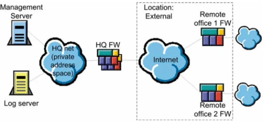
Because the IP addresses of the Management Server and the Log Server are translated, a Location and Contact Addresses must be defined. The Location element is used to group together elements that are on one side of a device that does Network Address Translation (NAT). Detailed instructions for configuring Locations and Contact Addresses can be found in the Installation Guide, the Administrator’s Guide, and the online help system of the Management Client.
Illustration 4: Example Scenario with Locations
As our illustration shows, only a single Location is needed in this case: the Location External that includes the remote office firewalls. This is because when the remote office firewalls communicate with the Management Server or Log Server, both firewalls are in contact with the same translated IP address, and if the remote office firewalls contact each other (to establish a VPN between the remote offices), there is no address translation between them. All other elements are left in the Default Location, which all system components are part of unless otherwise defined.
Defining Locations and Contact Addresses 6
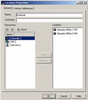
Illustration 5: Properties of the “External” Location
The illustration above shows the properties of the External Location fully configured with the two remote office firewalls. The Contact Addresses tab can be left empty in this scenario.
The next step is to define the Contact Address that the elements in the External Location should use when contacting the Management Server. This is done in the Management Server properties.
Illustration 6: Management Server Contact Address Settings
In the illustration above, a Contact Address dialog has been opened in the Management Server properties, and a Contact Address (the public IP address of the Management Server) has been added for the External Location. The next step is to define the Log Server Contact Address in the same way.
Defining Locations and Contact Addresses 7
Illustration 7: Log Server Contact Address Settings
After the Log Server receives its Contact Address definition for the External Location, the configuration is complete. The HQ firewall will start passing the traffic when its policy is refreshed. The administrators can take initial contact from the remote office firewalls to the Management Server’s public IP address to establish a trust relationship.
8 Trademarks and Patents
Stonesoft, the Stonesoft logo and StoneGate are all trademarks or registered trademarks of Stonesoft Corporation. Multi-link technology, multi-link VPN, and the StoneGate clustering technology-as well as other technologies included in StoneGate-are pro-tected by patents or pending patent applications in the U.S. and other countries. All other trademarks or registered trademarks are property of their respective owners.
Copyright and Disclaimer
Copyright © 2000–2006 Stonesoft Corporation. All rights reserved.
These materials, Stonesoft products and related documentation are protected by copyright and other laws, international treaties and conventions. All rights, title and interest in the materials, Stonesoft products and related documentation shall remain with Stonesoft and its licensors. All registered or unregistered trademarks in these materials are the sole property of their respective owners. No part of this document or related Stonesoft products may be reproduced in any form, or by any means without written authorization of Stonesoft Corporation.
Stonesoft provides these materials for informational purposes only. They are subject to change without notice and do not repre-sent a commitment on the part of Stonesoft. Stonesoft assumes no liability for any errors or inaccuracies that may appear in these materials or for incompatibility between different hardware components, required BIOS settings, NIC drivers, or any NIC configuration issues. Use these materials at your own risk. Stonesoft does not warrant or endorse any third party products described herein.
THESE MATERIALS ARE PROVIDED "AS-IS." STONESOFT MAKES NO WARRANTIES, EXPRESS OR IMPLIED, AS TO, THE INFORMA-TION CONTAINED HEREIN. IN ADDIINFORMA-TION, STONESOFT MAKES NO EXPRESS OR IMPLIED WARRANTIES OF MERCHANTABILITY OR FITNESS FOR A PARTICULAR PURPOSE OR USE WITH RESPECT THE INFORMATION CONTAINED IN THESE MATERIALS.
IN NO EVENT SHALL STONESOFT BE LIABLE FOR ANY INDIRECT, SPECIAL, CONSEQUENTIAL OR INCIDENTAL DAMAGES, INCLUD-ING, BUT NOT LIMITED TO, LOST PROFITS OR LOSS OR DAMAGE TO DATA ARISING FROM THE USE OF THESE MATERIALS, EVEN IF ADVISED IN ADVANCE OF THE POSSIBILITY OF SUCH DAMAGES.
Revision: SGHT_20060807
Stonesoft Corp.
Itälahdenkatu 22a FIN-00210 Helsinki Finland
tel. +358 9 4767 11 fax +358 9 4767 1234
Stonesoft Inc.
1050 Crown Pointe Parkway Suite 900
Atlanta, GA 30338 USA tel. +1 770 668 1125 fax +1 770 668 1131
Stonesoft Corp.
90 Cecil Street
#13-01 Carlton Building Singapore 069531 tel. +65 6325 1390 fax +65 6325 1399 www.stonesoft.com