GPS AutoSteer System
Installation Manual
Supported Vehicles
Non-AutoTrac Ready John Deere Combines
9650 STS 9660 STS 9550 CTS 9400 Walker 9600 Walker
9750 STS 9760 STS 9650 CTS 9410 Walker 9610 Walker
9560 STS 9860 STS 9660 CTS 9500 Walker 9650 Walker
9510 Walker 9660 Walker 9550 Walker
LEGAL DISCLAIMER
Note: Read and follow ALL instructions in this manual carefully before installing or operating the AutoSteer system.
Note: Take careful note of the safety information in the Safety Information section and throughout this manual.
The manufacturer disclaims any liability for damage or injury that results from failure to follow the instructions and warnings set forth herein.
Please take special note of the following warnings:
1. There is NO obstacle avoidance system included in the manufacturer’s product. Therefore, users must always have an operator on the equipment when the AutoSteer system is in use to look for any obstacles including people, animals, trees, ditches, buildings, etc.
2. During installation of the AutoSteer system and during the Calibration and Tuning processes the vehicle's wheels turn from side to side and the vehicle moves. Be sure that all people and obstacles are clear of the vehicle before installation, calibration and tuning, or use of the AutoSteer system.
3. Use of the AutoSteer system is NOT permitted while the vehicle is on public roads or in public areas. Ensure that the system is OFF before driving on roads or in public areas.
Special Requirements
Tools
This list consists of the tools required to complete the installation. The installer is assumed to have a complete set of common installation tools.
8mm socket and ratchet 1/2" wrench 16mm wrench
10mm socket and ratchet 9/16" wrench 16mm socket and ratchet 13mm socket, ratchet and extension 3/4” wrench 4mm Allen wrench
15mm socket and ratchet 13/16” wrench 5mm Allen wrench
24mm socket and ratchet 7/8” wrench 1/2" socket and ratchet
Electrical tape 15/16” wrench #1 Phillips screwdriver
Tape measure 12 ft (3.6 m) minimum 1” wrench #2 Phillips screwdriver 5/32" Allen wrench 1 1/16” wrench #2 Phillips stubby screwdriver
1/8" Allen wrench 1 1/8” wrench Hack saw
1/4" Allen wrench 1 1/4” wrench Step ladder
3/16" Allen wrench 15mm wrench Side cutters
3/8" open wrench 13mm wrench
Safety Information
Warning Alerts
The AutoSteer system installer and manufacturer disclaim any responsibility for damage or physical harm caused by failure to adhere to the following safety requirements:
•
As the operator of the vehicle, you are responsible for its safe operation.•
The steering system is not designed to replace the vehicle operator.Note: Verify that all screws, bolts, nuts, hose connections and cable connections are tight after the final installation of the AutoSteer system on the vehicle.
WARNING
To avoid electrical shock hazards, remove the Roof Module from the vehicle before driving under low structures or low electrical power lines.
WARNING
To prevent injury from falling, ensure you are in a stable position on the vehicle when installing or removing the Roof Rail and Roof Module. If the vehicle does not provide a safe platform, use a ladder to safely access the vehicle roof while installing or removing the Roof Rail and Roof Module.
WARNING
To prevent accidental death or injury from being run over by the vehicle, never leave the vehicle's operator chair with the AutoSteer system engaged.
WARNING
High-Pressure Fluid Hazard
Read the Owner’s Manual before installation. Wear hand and eye protection while performing hydraulic system maintenance. Relieve hydraulic system pressure before servicing the hydraulic system.
WARNING
To understand the potential hazards associated with the operation of AutoSteer equipment read the provided documentation before installing the AutoSteer system on a vehicle.
WARNING
To prevent the accidental engagement of the AutoSteer system and loss of vehicle control while driving on roads, shut down the AutoSteer system (exit the program). Never drive on roads or in public areas with the AutoSteer system turned on.
WARNING
Do not stand close to the wheels and do not move the machine while you are adjusting the relief valve. Turn off the engine and engage the parking brake before standing under or next to the machine.
Caution Alerts
The AutoSteer system installer and manufacturer disclaim any responsibility for damage or physical harm caused by failure to adhere to the following safety requirements:
CAUTION
The Roof Module must be removed when transporting or driving the vehicle at speeds above 30 mph (50 km/h). The Roof Module can possibly detach due to wind loads at higher speeds.
CAUTION
The AutoSteer system does not detect obstacles in the vehicle’s path. The operator must observe the path being driven in order to avoid obstacles.
CAUTION
When engaged, the AutoSteer system controls only the steering of the vehicle. The operator must control the speed of the vehicle.
CAUTION
The AutoSteer system must be powered OFF when installing or removing the Roof Module.
Vehicle Requirements
The vehicle steering and hydraulic systems must be in good working order before installing the AutoSteer system. Check for loose or worn parts. Before installing the AutoSteer system drive the vehicle and confirm that it steers straight and the wheels can be turned from lock to lock. Check the steering system hydraulic hoses and connections to ensure there are no oil leaks. The vehicle electrical system and battery must be in good working order.
The vehicle must be non-AutoTrac Ready. AutoTrac Ready model vehicles require a different installation kit. Contact your AutoSteer dealer for the correct installation kit.
The vehicle should be fully cleaned before installing the AutoSteer system. A clean vehicle improves the overall installation and cable routing and also reduces the chance for oil contamination when the hydraulic connections are opened. It is important to clean the area around the steering unit (Orbitrol), under the cab and behind the rear cab cover.
CAUTION
The Roof Module must always be firmly secured to the Roof Rail using the included hardware whenever the vehicle is in operation to prevent the Roof Module from releasing from its bracket and falling.
Important Information
Note: Verify all screws, bolts, nuts, hose connections and cable connections are tight after the AutoSteer system final installation.
Technical Support
Refer to your owner's manual for technical support information.
Contact Information
Table of Contents
Chapter 1 Installation Overview ...1
Kit Overview . . . 2
Assemblies . . . 2
Installation Procedure Outline . . . 8
Cable Diagram . . . 9
Chapter 2 Steering Valve Installation ...11
Steering Valve Installation Procedure Overview. . . 11
AutoSteer Valve Configuration . . . 12
LS Priority Valve Installation . . . 20
Identifying Orbitrol Ports . . . 23
Replacing the Priority Valve Damper Orifice . . . 25
Install the Valve Bracket . . . 27
Alternative Bracket Mounting Location . . . 29
Hydraulic Hose Connection Overview . . . 30
Hose Connection Diagram . . . 31
AutoSteer Valve Installation Checklist . . . 34
Chapter 3 Wheel Angle Sensor (WAS) Installation...35
9000 STS Wheel Angle Sensor Installation Procedure . . . 35
Mounting Wheel Angle Sensor Hardware. . . 36
Cutting Linkage Rods to Length . . . 39
Assembling Linkage Rod Hardware . . . 41
Attaching and Adjusting Wheel Angle Sensor Linkage Rods. . . 44
9000 CTS Wheel Angle Sensor Installation Procedure . . . 52
Mounting Wheel Angle Sensor Hardware. . . 53
Cutting Linkage Rods to Length . . . 55
Assembling Linkage Rod Hardware . . . 57
Attaching and Adjusting Wheel Angle Sensor Linkage Rods. . . 59
Chapter 4 SA Module Installation ...67
Chapter 5 Roof Module Installation...73
Safety Notes . . . 73
Installation Procedure . . . 74
Display . . . 99
SAM Harness. . . 99
Main Cable Harness Connections Inside Cab . . . 100
Power Supply Connections . . . 101
Cab Power Connection . . . 101
Battery Power Connection . . . 102
Chapter 8 Post-Installation Procedures and Information...103
Verify the Vehicle is Ready for AutoSteer . . . 103
Create a New Vehicle . . . 103
Calibration and Tuning Notes . . . 103
Vehicle Specific Installation Calibration and Tuning Guidelines . . . 103
1
Installation Overview
This Installation Overview chapter contains part numbers, kit overview diagram, cabling diagram and the installation procedure for the John Deere Installation Kit.
•
Kit Overview•
Assemblies•
AutoSteer Valve Kit Components•
Hose Kit Components•
Bracket Kit Components•
Installation Procedure Outline•
Cable DiagramNote: If you are installing an electric steering wheel actuator such as OnTrac II, skip the SA Module, Steering Valve connection and System Cable connection installation provided in this manual. Refer to your electric steering product manual for additional instructions.
This installation guide describes the installation of the AutoSteer system on several models of John Deere combines. The AutoSteer installation kit PN: 188-0031-01 is used on these series of combines. The vehicle specific sub-assemblies for the combine series are listed in Table 1-1.
Table 1-1 Part Numbers
John Deere 9000 Combines 152-0033-01
153-0001-01 500-0303-01
Kit Overview
Kit Overview
Figure 1-1 AutoSteer Kit Components (PN: 188-0031-01)
Table 1-2 AutoSteer Kit Components (PN: 188-0031-01)
Assemblies
Item Component Part Number
1. AutoSteer Valve Kit 153-0001-01
2. Hydraulic Hose Kit 500-0303-01
Assemblies
AutoSteer Valve Kit Components
Figure 1-2 Installation Kit Sub-Assembly (PN: 153-0001-01)
Table 1-3 Installation Kit Sub-Assembly Components (PN: 153-0001-01)
Item Component Part Number
1. SA Module Harness 201-0371-02
Assemblies
Hose Kit Components
Figure 1-3 Hose Kit Components (PN: 500-0303-01)
Table 1-4 Hose Kit Components (PN: 500-0303-01)
15. SA Module Assembly 200-0206-01
Item Component Part Number
Assemblies
5. Hose Assembly 3/8” x 60” F451TC-JCJC060806-60
6. Adapter 10 F65OL-S
7. Adapter 8-10 F5OG5-S
8. Adapter 4 F5OLO
9. Adapter Run Tee 8 R6LO-S
10. Adapter Elbow 8 C6LO
11. Adapter 45 Degree 8 V6LO-S
12. Adapter 90 Degree 6C6LO
13. Adapter Run Tee 6 R6LO
14. Check Valve DT-370-MOMS-65
15. Adapter Run Tee 10 R6LO-S
16. Adapter Expander 10-6 TRLON-S
17. Adapter 8 F5OLO
18. Adapter 10-8 F5OLO-S
19. Adapter 10 V6LO-S
20. Cable Tiesa 200-0467-01
a. The colored cable ties included in the kit are used to identify the hydraulic hoses. Place identical colored cable ties at the ends of each hydraulic hose to positively identify the hose.
Note: The suggested hose color assignments are as follows: Pressure - Red
Return - Green LS Orbitrol - Blue LS Out - Grey Steer Right - Yellow Steer Left - Orange
Assemblies
Bracket Kit Components
Assemblies
4. Cable Routing Hardware 200-0174-01
8. Termination Kit 200-0481-01
9. Power Adapter Cable 201-0368-01
10. LS Priority Valve 500-0340-01
Installation Procedure Outline
Installation Procedure Outline
Note: The system interconnect cable diagram in the Cable Diagram on page 9 section of this chapter shows the A5 AutoSteer electrical connections.
1. Verify shipped components.
2. Install the Hydraulic Valve Assembly. 3. Install the Hydraulic Hoses.
4. Install the Wheel Angle Sensor. 5. Install the SA Module.
6. Install the Roof Module. 7. Install the Display.
8. Install the Main Cable Harness and the SA Module Harness. 9. Ensure all connectors are properly coupled.
10.Power ON the AutoSteer system. 11.Calibrate the vehicle.
12.Tune the vehicle.
Cable Diagram
2
Steering Valve Installation
This Steering Valve Installation chapter contains information in the following sections:
•
Steering Valve Installation Procedure Overview•
AutoSteer Valve Configuration•
AutoSteer Valve Configuration•
LS Priority Valve Installation•
Identifying Orbitrol Ports•
Replacing the Priority Valve Damper Orifice•
Install the Valve Bracket•
Alternative Bracket Mounting Location•
Hydraulic Hose Connection Overview•
Hose Connection Diagram•
AutoSteer Valve Installation ChecklistSteering Valve Installation Procedure Overview
1. Install an internal plug to configure the AutoSteer valve for Open Center Steering installation. 2. Install the AutoSteer valve bracket and valve on the vehicle.3. Connect the LS Priority valve to the Orbitrol pressure port. 4. Connect the hoses between the AutoSteer valve and the vehicle. 5. Check for oil leaks.
6. Adjust the AutoSteer pressure relief valve.
7. Perform a functional test to confirm correct valve operation.
AutoSteer Valve Configuration
AutoSteer Valve Configuration
Replace plug 13A in the AutoSteer valve with a 0.022” orifice to configure the valve for Open Center Steering operation. Follow the procedure shown below.
Note: The AutoSteer valve will not operate correctly if you do not install the orifice.
1. Use a 3/16” Allen key to remove the four cover screws. See Figure 2-1.
2. Remove the front cover to access the hose connections, pressure transducer and relief valve. See Figure 2-1.
Figure 2-1 Steering Valve Assembly
AutoSteer Valve Configuration
Figure 2-2 AutoSteer Valve Port Identification
Note: The ports shown in Figure 2-2 are upside-down relative to the ports shown in Figure 2-1.
Table 2-1 Valve Functions and Fitting Sizes
Hose Adapter Fitting Type/Size
PRESS = PUMP PRESSURE -8 ORFS
TANK = TANK / RETURN -6 ORFS
LS ORBITROL = LS FROM ORBITROL -4 ORFS
LS OUT = LS -4 ORFS
LEFT = LEFT STEERING CYLINDER -6 ORFS RIGHT = RIGHT STEERING CYLINDER -6 ORFS
GP = DIAGNOSTICS PORT 1/8”
AutoSteer Valve Configuration
3. Identify the threaded plug shipped with the valve in a parking position identified as PLUG on the front face. See
Figure 2-3.
Note: The plug does not have a hole and must not be mistaken with the two orifices which are also shipped next to the plug on the valve. See Figure 2-3.
Figure 2-3 Steering Valve With Cover Removed
Table 2-2 Plug and Orifice Configuration Summary
Type of Installation 13A 13B 13C
Factory Default Configuration Plug Open Plug
Open Center Orbitrol Using Priority Valve 0.022 Orifice Plug Plug
Plug
AutoSteer Valve Configuration
4. Identify the large external access plug identified in position 13B.
5. Remove the external plug in position 13B using a 1/4” hex key. See Figure 2-4.
Figure 2-4 Removing External Plug
6. Remove the small plug from position PLUG using a 1/8” hex key. See Figure 2-5.
Figure 2-5 Remove Plug
AutoSteer Valve Configuration
7. Install the small plug inside the hole in position 13B. The plug engages an existing thread about 1 inch below the surface. See Figure 2-6.
Note: Do not over tighten the plug.
AutoSteer Valve Configuration
8. Re-install the large external plug in position 13B.
9. Remove the large external plug identified as 13A on the valve right side using a 1/4” Allen key.
Note: Plug 13A is located on the side of the compact valve. See Figure 2-7.
Figure 2-7 Plug 13A Location
AutoSteer Valve Configuration
10.Remove the small internal plug in position 13A using a 1/8” Allen key. See Figure 2-8.
Figure 2-8 Internal Plug Removal
11.Replace the small internal blind plug in position 13A with a 0.022” diameter orifice removed from the front of the valve.
Note: The orifice enables Load Sense bleed-down to reduce pump pressure.
12.Thread the orifice into the bottom of cavity 13A and tighten. 13.Replace the large external plug in position 13A.
Note: The small blind plug that was removed from position 13A can be threaded into the front of the valve for storage and future use.
Note: A check valve must be installed on the AutoSteer Return port for improved manual steering and kick-out. A Parker check valve is provided as a loose part in the STS hose kit. Install the check valve before installing the AutoSteer valve on the machine. Use a work bench or table to work on the valve.
AutoSteer Valve Configuration
14.Remove the -6 ORFS hose adapter from the port identified as TANK. See Figure 2-9.
Note: You may have to remove adjacent adapters or the rear valve cover for better access to the Return/Tank port.
Figure 2-9 Tank/Return Port Location
15.Install the threaded check valve provided in your hose kit.
Note: The check valve looks just like a normal hose adapter but has an internal spring.
16.Tighten the check valve and replace any parts removed for ease of access.
Note: The AutoSteer valve uses a Load Sense relief valve to limit the maximum pump pressure by limiting the maximum Load Sense pressure output. The relief valve will only limit the maximum pump pressure while AutoSteering. The maximum manual steering pressure is set by a separate relief valve inside the vehicle Orbitrol.
Return/Tank Port
LS Priority Valve Installation
17.Loosen the jam nut on the relief valve using a ½” combination wrench. See Figure 2-10.
Figure 2-10 Adjusting the Relief Valve
Note: The AutoSteer relief valve is set at the factory to 3000psi and can be adjusted in the field between zero and 3600psi.
18.Loosen the set screw (to reduce the relief pressure) by turning it two complete turns with a 5/32” Allen key in the counter-clockwise direction.
19.Leave the jam nut loose because further adjustments of the relief valve are required after the installation is completed. 20.This concludes the valve configuration. The valve is now ready for vehicle installation.
LS Priority Valve Installation
An Open Center Orbitrol usually has only four hoses (pressure, return, right, left) and does not have a load sense hose. A Load Sense Priority Valve is required to complete the AutoSteer hydraulic installation on Open Center Orbitrols. The AutoSteer LS priority valve provides oil pressure on demand to the AutoSteer valve.
The parts shown below are provided with the AutoSteer installation kit for Open Center steering systems. Figure 2-11 shows the priority valve and Figure 2-12 shows the priority valve in-line mounting installation.
LS Priority Valve Installation
Note: Ensure the LS Priority Valve is properly oriented and all hose connections are correct and tight before starting the engine. Inverting the PUMP IN and ORBITROL ports on the LS Priority Valve causes immediate pump damage when the engine is started because the priority valve only allows oil flow in one direction.
LS Priority Valve Installation
Figure 2-12 Priority Valve Mounted In-Line
Figure 2-13 shows the LS priority valve installed directly on the Orbitrol pressure port. This type of installation is preferred when there is sufficient clearance in front of the Orbitrol. The threaded adapters provided with your adapter kit enable this type of installation.
Identifying Orbitrol Ports
Note: The hose adapter type and size must match the vehicle’s hose fittings.
Figure 2-13 Priority Valve Mounted Directly on the Orbitrol
Identifying Orbitrol Ports
The ports on the Orbitrol under the cab front must be clearly identified before you start to connect hoses. Use Figure 2-14
through Figure 2-16 to positively identify all Orbitrol ports.
Note: To avoid pump damage caused by wrong hose connections, the Pressure and Return ports on the Orbitrol must be positively identified. Before connecting hoses, confirm that the Pressure and Return ports on your machine are as shown on this page. The Pressure port can be positively identified by following the hose that leads to the gear pump in the engine bay or the attenuator. The Return port can be positively identified by following the hose that leads to the return oil
Identifying Orbitrol Ports
Figure 2-14 Orbitrol Port Identification
Figure 2-15 Orbitrol Ports (view 1)
T = Return/Tank L = Left
P = Pressure
LS = Load Sense (Load Sense is not used on this machine) R = Right
Orbitrol
Left Port
Replacing the Priority Valve Damper Orifice
Figure 2-16 Orbitrol Ports (view 2)
Replacing the Priority Valve Damper Orifice
A smaller damper orifice is provided attached to the LS priority valve and may be used to replace the factory installed orifice if you experience chatter (hydraulic noise) when AutoSteering. Figure 2-17 shows the priority valve damper orifice location. Follow this procedure to replace the damper orifice:
1. Remove the external plug at position 4 using a 3/16” hex key. 2. Remove the existing internal orifice at 4 using a 1/8” hex key.
3. Remove the spare orifice at ORIF using a 1/8” hex key and then install it at 4. 4. Replace the external plug at 4 and tighten.
5. Store the removed orifice at the parking position ORIF.
Note: Always clean the orifice and confirm the hole is not blocked before installing it in the valve.
Return Port
Replacing the Priority Valve Damper Orifice
Figure 2-17 Damper Orifice Location
Spare Orifice
Replace Orifice Under the External Plug
Load Sense Priority Valve
Install the Valve Bracket
Install the Valve Bracket
The AutoSteer valve should be installed under the cab in the position shown using the valve bracket and mounting bolts provided in the bracket kit. See Figure 2-18. An L valve bracket is used to secure the valve to the vehicle using bolts provided in the kit. Hoses are connected to the steering lines and Orbitrol ports.
Figure 2-18 AutoSteer Valve Bracket Mounting Location
AutoSteer Valve Bracket Mounting Hole Locations
Install the Valve Bracket
1. Install the L valve bracket in the position shown in Figure 2-19 and secure using two bolts provided in the bracket kit.
Note: The valve position must enable the hoses to reach the steering unit (Orbitrol). Secure the valve bracket to the frame using one of the two valve brackets and the supplied hardware. If possible, use existing holes in the frame to secure the valve bracket.
2. Secure the valve to the bracket using four 5/16” hex screws provided with the kit.
Note: Alternatively, you may secure the valve to the bracket using two long 5/16” Allen screws provided with the kit.
3. Remove the front valve cover using a 3/16” Allen key to loosen the four screws.
Note: The valve front cover must be removed to provide access to hose connections.
Figure 2-19 Steering Valve Mounted on Bracket
Alternative Bracket Mounting Location
Alternative Bracket Mounting Location
The AutoSteer valve may be installed in alternative mounting positions depending on the exact machine model and available mounting holes or bolts. Figure 2-20 shows a possible alternative steering valve location.
Hydraulic Hose Connection Overview
Hydraulic Hose Connection Overview
1. Refer to Figure 2-21 for a detailed hose diagram and follow the instructions below.2. Disconnect the pressure hose from the Orbitrol and connect it to the LS Priority Valve PUMP IN port.
Note: Use an extender hose or thread adapter as required to complete this hose connection.
3. Connect a hose from the LS Priority Valve PRESSURE OUT port to the AutoSteer valve PRESS port. 4. Connect a hose from the AutoSteer valve LS Orbitrol port to the LS Priority Valve SIGNAL OUT port. 5. Install a 65psi check valve on the AutoSteer valve Return port.
Note: The check valve should have previously been completed during valve configuration.
6. Install a tee adapter on the Orbitrol Return port. You can install this tee anywhere along the Return hose between the Orbitrol and the Return.
7. Connect a hose between the check valve installed on the AutoSteer valve Return port to the Orbitrol Return line installed Tee adapter.
8. Connect a hose between the AutoSteer valve LS Out port and the LS Priority Valve LS IN port. 9. Connect a threaded adapter from the LS Priority Valve ORBITROL port to the Orbitrol Pressure port. 10.Connect a hose between the AutoSteer valve Left port and the Orbitrol left steering hose.
Note: You may install the tee adapter anywhere along the left steering line in a convenient location. See Figure 2-24.
11.Connect a hose between the AutoSteer valve Right port and the Orbitrol right steering hose.
Note: You may install the tee adapter anywhere along the right steering line in a convenient location. See Figure 2-24.
12.Install the pressure transducer in the TRANS port. Do not overtighten.
Hose Connection Diagram
Note: Keep all hoses away from moving parts or removable access panels.
17.Proceed to the calibration and tuning process.
Hose Connection Diagram
Hose Connection Diagram
Figure 2-22 Orbitrol to Priority Valve Connection
Figure 2-23 Left Steering Valve Connection on Orbitrol
Orbitrol
Priority Valve
Hose Connection Diagram
Figure 2-24 Completed Left and Right Steering Orbitrol Connections
Left Steering Tee
AutoSteer Valve Installation Checklist
AutoSteer Valve Installation Checklist
1. Configure the AutoSteer valve with correct plugs and orifice.2. Ensure the valve bracket bolts are tight.
3. Ensure mounting screws securing the AutoSteer valve are tight.
4. Ensure the Pump pressure hose is connected to the correct Priority valve port. 5. Ensure the Return hose is connected to correct AutoSteer valve and Orbitrol ports. 6. Ensure the LS-OUT hose connected to correct AutoSteer valve and Priority valve ports. 7. Ensure the LS ORBITROL (LS IN) hose is connected to the correct ports at both ends. 8. Ensure the Right Steer hose is connected correctly at both ends.
9. Ensure the Left Steer hose is connected correctly at both ends. 10.Ensure the Pressure Transducer is installed and tight.
11.Ensure all hose fittings are connected and tight.
12.Check hose routing and ensure hoses are secured with cable ties. 13.Ensure the SA Module Harness is connected to both valve connectors. 14.Ensure the valve test port has the 5000psi pressure gauge installed. 15.Ensure the AutoSteer valve Return port Check Valve was installed. 16.Ensure the hoses do not interfere with vehicle operation.
3
Wheel Angle Sensor (WAS) Installation
This Wheel Angle Sensor Installation chapter information is provided in the following sections:
•
9000 STS Wheel Angle Sensor Installation Procedure•
Mounting Wheel Angle Sensor Hardware•
Cutting Linkage Rods to Length•
Assembling Linkage Rod Hardware•
Attaching and Adjusting Wheel Angle Sensor Linkage Rods•
9000 CTS Wheel Angle Sensor Installation Procedure•
Mounting Wheel Angle Sensor Hardware•
Cutting Linkage Rods to Length•
Assembling Linkage Rod Hardware•
Attaching and Adjusting Wheel Angle Sensor Linkage RodsNote: The Wheel Angle Sensor is optional equipment and is not provided with the installation kit. The Wheel Angle Sensor installation instructions are provided for special installations, when required.
9000 STS Wheel Angle Sensor Installation Procedure
Figure 3-1 shows the 9000 STS Non-AT Ready combine Wheel Angle Sensor assembly fully assembled.
Figure 3-1 Wheel Angle Sensor Components
Shield
Wheel Angle Sensor Tie Rod Bracket
Mounting Wheel Angle Sensor Hardware
Mounting Wheel Angle Sensor Hardware
1. Find the Wheel Angle Sensor bracket mounting location.Note: The bracket should be located on the vehicle’s rear axle left side. See Figure 3-2.
Figure 3-2 Wheel Angle Sensor Bracket Location
Mounting Wheel Angle Sensor Hardware
2. Mount the Wheel Angle Sensor bracket. See Figure 3-3. 3. Secure with a bolt provided in your kit.
Figure 3-3 Wheel Angle Sensor Bracket Mounted
4. Install the Wheel Angle Sensor on the bracket as shown in Figure 3-4.
Figure 3-4 Wheel Angle Sensor Mounted (shown with linkage rods attached)
Wheel Angle Sensor Bracket Mounted
Mounting Wheel Angle Sensor Hardware
5. Install the linkage rod L bracket on the tie rod using a muffler clamp. See Figure 3-5.
Figure 3-5 Linkage Rod L Bracket
L Bracket
Cutting Linkage Rods to Length
Note: The threaded linkage rods must be cut to the correct lengths before final assembly. The linkage rods are shown assembled in Figure 3-6. See Table 3-1 and Table 3-2 for the cut and assembled linkage rod lengths.
Figure 3-6 Wheel Angle Sensor Assembly Completely Assembled
Cutting Linkage Rods to Length
1. Measure and mark the two rods for cutting, according to the length shown in Table 3-1.
Note: Before cutting the linkage rods, verify the Wheel Angle Sensor brackets will attach to the vehicle as shown in this manual and they are attached the correct distance from any reference points shown. If this is not possible, do not cut the rods until it is determined if these lengths work for your installation. Due to possible variations in the mounting positions, these measurements could be different. These measurements are provided as a reference only. The installer is responsible for ensuring the rods are cut to the proper length.
Table 3-1 Linkage Rod Cut Lengths
Cutting Linkage Rods to Length
Note: Figure 3-7 shows the measurement points used to properly cut the linkage rods.
Assembling Linkage Rod Hardware
2. Use a hack saw to cut the linkage rod to length while it is held in a bench vise. See Figure 3-8.
Figure 3-8 Linkage Rod Cutting
Assembling Linkage Rod Hardware
Note: The after-assembly center-to-center lengths of each linkage rod are shown in Table 3-2. Figure 3-9 shows the measurement points for the assembled linkage rods.
Table 3-2 Assembled Linkage Rod Length
Item Length
Rod A 6.7 inches (170 mm)a
a. This measurement is the rod length after assembly with the ball joints.
Assembling Linkage Rod Hardware
Figure 3-9 Linkage Rod (Assembled) Measurement Points
Note: The threaded rods must be cut to the correct lengths before final assembly.
1. Attach a jam nut to the Rod A end. See Figure 3-10.
2. Connect the eye connector to the Wheel Angle Sensor rod end. As shown in Figure 3-10.
Figure 3-10 Rod A Assembled
Rod A Measurement
Rod B Measurement
Eye Connector
Assembling Linkage Rod Hardware
3. Attach the jam nuts to each end of linkage Rod B
4. Attach the ball joints to both ends of the linkage arm as shown in Figure 3-11.
Note: This installation requires the bolts for the ball joints should be facing the opposite direction as shown in
Figure 3-11.
Figure 3-11 Linkage Rod Assembled
Ball Joints Jam Nuts
Attaching and Adjusting Wheel Angle Sensor Linkage Rods
Attaching and Adjusting Wheel Angle Sensor Linkage Rods
1. Install the short linkage arm on the Wheel Angle Sensor shaft.2. Ensure a flat washer is placed under the screw head when attaching the linkage rod to the sensor shaft. See Figure 3-12.
Note: The washer should be on the bolt head side and not the assembly nut side.
Figure 3-12 Washer on Shaft Screw
Flat Washer
Screw Head
Attaching and Adjusting Wheel Angle Sensor Linkage Rods
Note: Do not turn the wheels or drive the combine before the Wheel Angle Sensor has been adjusted using the AutoSteer Calibration screens. The potentiometer can only rotate a maximum of 180 degrees and if it is rotated beyond its mechanical stops, it will be permanently damaged.
3. Install the long threaded linkage on the tie rod bracket using a ball joint.
4. With the linkage rods disconnected, turn the steering wheel so the wheels are centered (the vehicle will travel straight ahead when moving).
5. Temporarily attach the linkage rods.
Note: Never leave the linkage rods attached to Wheel Angle Sensor rod and turn the steering wheels manually or automatically until the fit has been verified. The linkage rods must remain apart while the steering wheels are turned to the maximum right and left positions and then temporarily attached at these positions. Failure to disconnect the linkage rods may cause the Wheel Angle Sensor or vehicle to become damaged.
Note: After the linkage rods are assembled, they should move freely without touching any other parts and without overextending. Make any necessary adjustments to the linkage rods, if there is mechanical interference.
WARNING
Always shut down the vehicle when working around the steering axle while checking and adjusting the Wheel Angle Sensor rod lengths. The steering axle could move suddenly and cause severe injury or death.
Attaching and Adjusting Wheel Angle Sensor Linkage Rods
6. Rotate the Wheel Angle Sensor potentiometer on top of the mounting block so the wire connector is parallel to the Wheel Angle Sensor linkage rod. See Figure 3-13.
Figure 3-13 Adjusting Potentiometer Angle
Attaching and Adjusting Wheel Angle Sensor Linkage Rods
7. Tighten the two screws securing the potentiometer to the Wheel Angle Sensor, after final adjustments. See Figure 3-14.
Note: Use a 5/32” hex key and a 3/8” wrench to secure the potentiometer. See Figure 3-14.
Figure 3-14 Wheel Angle Sensor Potentiometer (shown on bench)
Attaching and Adjusting Wheel Angle Sensor Linkage Rods
9. Reattach the linkage assembly and verify the sensor will not be damaged. See Figure 3-15. 10.Adjust the linkage rod lengths as necessary.
Figure 3-15 Wheels Turned Full Left
11.Disconnect the linkage rods and turn the steering wheel manually to the full right position. See Figure 3-16. 12.Reattach the linkage assembly and verify the sensor will not be damaged.
13.Adjust the linkage rod lengths as necessary.
Attaching and Adjusting Wheel Angle Sensor Linkage Rods
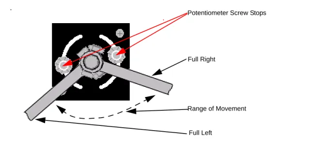
14.Repeat Step 4. through Step 13. until the linkage rod lengths have been adjusted and the potentiometer is centered to obtain the maximum sensor movement.
Note: The maximum movement is reached when the Wheel Angle Sensor rod sweeps from approximately 3/16 inch (5mm) from the screw stops when the wheels are turned to the maximum right and left positions. See Figure 3-17.
Figure 3-17 Maximum Sensor Movement (as seen from bottom)
Note: An Ohm meter can also be used to determine if there is enough sensor movement. Connect the Ohm meter to pins A and B of the Wheel Angle Sensor. Measure the Ohm reading at the maximum left and right position. After subtracting the smaller number from the larger number, there should be at least a 3.75 Kohms change. The reading should also never go below 1.6 or higher than 6.6 Kohms as this is reaching the limits of the potentiometer and could damage the sensor.
Potentiometer Screw Stops
Full Left
Range of Movement Full Right
Attaching and Adjusting Wheel Angle Sensor Linkage Rods
15.Tighten all linkage rod jam nuts.
16.Tighten the bolt securing the two linkage rods together. See Figure 3-18.
Figure 3-18 Linkage Rod Ball Joint Bolt (different vehicle shown)
17.Tighten the screw on the sensor shaft. Use a 1/8” hex key and a 3/8” wrench. See Figure 3-19.
Attaching and Adjusting Wheel Angle Sensor Linkage Rods
Note: The AutoSteer system must be fully functional before you can perform Step 19.
19.Adjust the arm length until there are approximately 48000 counts from the Wheel Angle Sensor using the AutoSteer diagnostics screen.
Note: If necessary, shorten Rod A to increase the Wheel Angle Sensor counts.
20.Tighten all jam nuts and fasteners.
21.Figure 3-20 shows the completed Wheel Angle Sensor installation.
9000 CTS Wheel Angle Sensor Installation Procedure
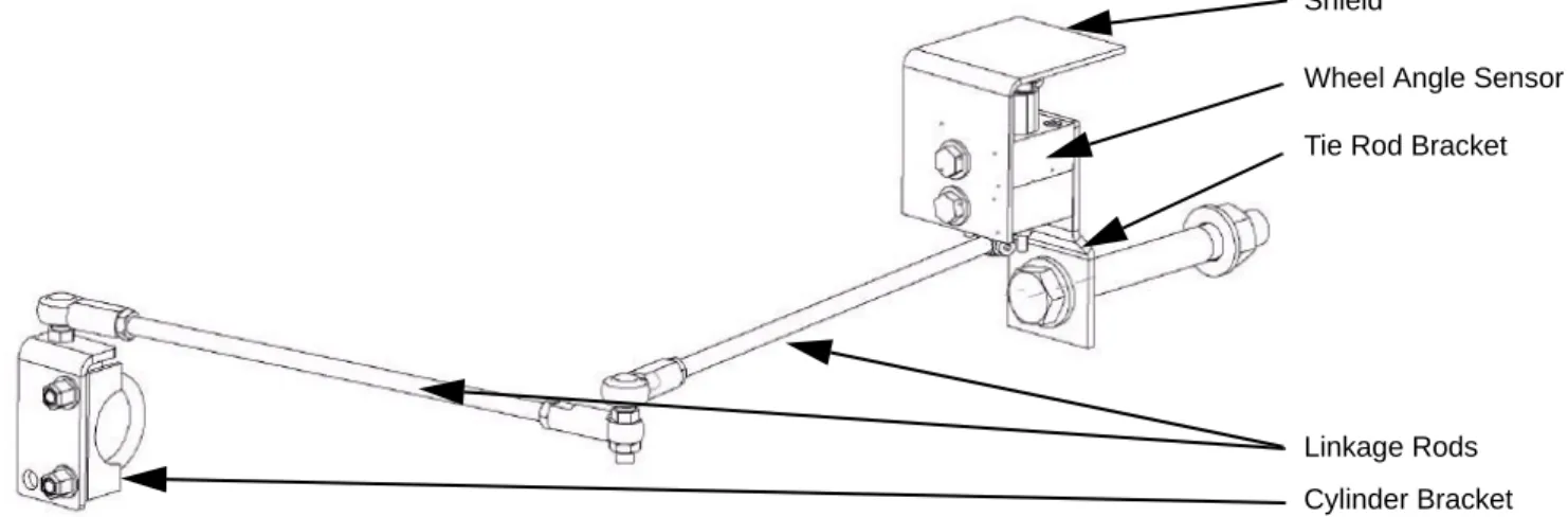
9000 CTS Wheel Angle Sensor Installation Procedure
Figure 3-21 shows the 9000 CTS Non-AutoTrac Ready combine Wheel Angle Sensor assembly fully assembled.
Figure 3-21 Wheel Angle Sensor Components
Tie Rod Bracket
Linkage Rods Wheel Angle Sensor
Cylinder Bracket Shield
Mounting Wheel Angle Sensor Hardware
Mounting Wheel Angle Sensor Hardware
1. Mount the Wheel Angle Sensor bracket. See Figure 3-22.2. Secure the cylinder bracket with the U-Bolt provided in your kit. See Figure 3-22.
Note: Do not overtighten.
Figure 3-22 Wheel Angle Sensor Brackets Mounted
U-Bolt Clamp
Wheel Angle Sensor Bracket Wheel Angle Sensor Shield
Mounting Wheel Angle Sensor Hardware
3. Mount the linkage rod L bracket by removing the existing steering cylinder bolt and replacing it with the bolt provided in your kit. See Figure 3-23.
Figure 3-23 Linkage Rod Bracket and Bolt
4. Secure the Wheel Angle Sensor to the cylinder bracket using the bolt provided in your kit. See Figure 3-24.
Figure 3-24 Wheel Angle Sensor and Bracket Mounted
Linkage Bracket Bolt Linkage Bracket
Cutting Linkage Rods to Length
Note: The threaded linkage rods must be cut to the correct lengths before final assembly. The linkage rods are shown assembled in Figure 3-25. See Table 3-3 and Table 3-4 for the cut and assembled linkage rod lengths.
Figure 3-25 Wheel Angle Sensor Assembly Assembled
Cutting Linkage Rods to Length
1. Measure and mark the two rods for cutting, according to the length shown in Table 3-3.
Note: Before cutting the linkage rods, verify the Wheel Angle Sensor brackets will attach to the vehicle as shown in this manual and they are attached the correct distance from any reference points shown. If this is not possible, do not cut the rods until it is determined if these lengths work for your installation. Due to possible variations in the mounting positions, these measurements could be different. These measurements are provided as a reference only. The installer is responsible for ensuring the rods are cut to the proper length.
Cutting Linkage Rods to Length
Note: Figure 3-26 shows the measurement points used to properly cut the linkage rods.
Figure 3-26 Linkage Rod Cut Length Measurement Points
2. Use a hack saw to cut the linkage rod to length while it is held in a bench vise. See Figure 3-27.
Assembling Linkage Rod Hardware
Assembling Linkage Rod Hardware
Note: The after-assembly center-to-center lengths of each linkage rod are shown in Table 3-4. Figure 3-28 shows the measurement points for the assembled linkage rods.
Table 3-4 Assembled Linkage Rod Length
Figure 3-28 Linkage Rod (Assembled) Measurement Points
Item Length
Rod A 5.5 inches (140 mm)a
a. This measurement is the rod length after assembly with the ball joints.
Rod B 14.0 inches (356 mm)a
Rod A Measurement
Rod B Measurement
Assembling Linkage Rod Hardware
1. Attach a jam nut to the Rod A end. See Figure 3-29.
2. Connect the eye connector to the Wheel Angle Sensor rod end. As shown in Figure 3-29.
Figure 3-29 Rod A Assembled
3. Attach the jam nuts to each end of linkage Rod B
4. Attach the ball joints to both ends of the linkage arm as shown in Figure 3-30.
Note: This installation requires the bolts for the ball joints should be facing the direction shown in Figure 3-30.
Figure 3-30 Linkage Rod Assembled
Eye Connector
Jam Nut
Ball Joints Jam Nuts
Attaching and Adjusting Wheel Angle Sensor Linkage Rods
Attaching and Adjusting Wheel Angle Sensor Linkage Rods
1. Install the short linkage arm on the Wheel Angle Sensor shaft.2. Ensure a flat washer is placed under the screw head when attaching the linkage rod to the sensor shaft. See Figure 3-31.
Note: The washer should be on the bolt head side and not the nut side of the assembly.
Figure 3-31 Washer on Shaft Screw
Flat Washer
Screw Head
Attaching and Adjusting Wheel Angle Sensor Linkage Rods
Note: Do not turn the wheels or drive the combine before the Wheel Angle Sensor has been adjusted using the AutoSteer Calibration screens. The potentiometer can only rotate a maximum of 180 degrees and if it is rotated beyond its mechanical stops, it will be permanently damaged.
3. Install the long threaded linkage on the tie rod bracket using a ball joint.
4. With the linkage rods disconnected, turn the steering wheel so the wheels are centered (the vehicle will travel straight ahead when moving).
5. Temporarily attach the linkage rods.
Note: Never leave the linkage rods attached to Wheel Angle Sensor rod and turn the steering wheels manually or automatically until the fit has been verified. The linkage rods must remain apart while the steering wheels are turned to the maximum right and left positions and then temporarily attached at these positions. Failure to disconnect the linkage rods may cause the Wheel Angle Sensor or vehicle to become damaged.
Note: After the linkage rods are assembled, they should move freely without touching any other parts and without overextending. Make any necessary adjustments to the linkage rods, if there is mechanical interference.
WARNING
Always shut down the vehicle when working around the steering axle while checking and adjusting the Wheel Angle Sensor rod lengths. The steering axle could move suddenly and cause severe injury or death.
Attaching and Adjusting Wheel Angle Sensor Linkage Rods
6. Rotate the Wheel Angle Sensor potentiometer on top of the mounting block so the wire connector is parallel to the Wheel Angle Sensor linkage rod.
Figure 3-32 Adjusting Potentiometer Angle
Attaching and Adjusting Wheel Angle Sensor Linkage Rods
7. Tighten the two screws securing the potentiometer to the Wheel Angle Sensor, after final adjustments. See Figure 3-33.
Note: Use a 5/32” hex key and a 3/8” wrench to secure the potentiometer. See Figure 3-33.
Figure 3-33 Wheel Angle Sensor Potentiometer (shown on bench)
8. Disconnect the linkage rods and turn the steering wheel manually to the full left position. 9. Reattach the linkage assembly and verify the sensor will not be damaged.
10.Adjust the linkage rod lengths as necessary.
11.Disconnect the linkage rods and turn the steering wheel manually to the full right position. 12.Reattach the linkage assembly and verify the sensor will not be damaged.
13.Adjust the linkage rod lengths as necessary.
14.Repeat Step 4. through Step 13. until the linkage rod lengths have been adjusted and the potentiometer is centered to obtain the maximum sensor movement.
Attaching and Adjusting Wheel Angle Sensor Linkage Rods
Figure 3-34 Maximum Sensor Movement (as seen from bottom)
Note: An Ohm meter can also be used to determine if there is enough sensor movement. Connect the Ohm meter to pins A and B of the Wheel Angle Sensor. Measure the Ohm reading at the maximum left and right position. After subtracting the smaller number from the larger number, there should be at least a 3.75 Kohms change. The reading should also never go below 1.6 or higher than 6.6 Kohms as this is reaching the limits of the potentiometer and could damage the sensor.
Potentiometer Screw Stops
Full Left
Range of Movement Full Right
Attaching and Adjusting Wheel Angle Sensor Linkage Rods
15.Tighten all linkage rod jam nuts.
16.Tighten the bolt securing the two linkage rods together. See Figure 3-35.
Figure 3-35 Linkage Rod Ball Joint Bolt (different vehicle shown)
17.Tighten the screw on the sensor shaft. Use a 1/8” hex key and a 3/8” wrench. See Figure 3-36.
Attaching and Adjusting Wheel Angle Sensor Linkage Rods
Note: The AutoSteer system must be fully functional before you can perform Step 19.
19.Adjust the arm length until there are approximately 48000 counts from the Wheel Angle Sensor using the AutoSteer diagnostics screen.
Note: If necessary, shorten Rod A to increase the Wheel Angle Sensor counts.
20.Tighten all jam nuts and fasteners.
21.Figure 3-37 shows the completed Wheel Angle Sensor installation.
4
SA Module Installation
This SA Module Installation chapter contains information for mounting the SA Module bracket and installing the SA Module.
Note: The following procedure provides possible SA Module mounting instructions. However due to the variety of vehicle options available on vehicles and possible configuration differences, it may be necessary to install the SA Module in an alternative location. If an alternative location is required, choose a location where the SA Module can be protected from damage from moving parts or crop debris and excessive moisture from weather and cleaning equipment.
1. Mount the SA Module bracket on the vehicle frame side. See Figure 4-1.
Figure 4-1 SA Module Location
SA Module Installation
2. Identify the holes on the grain tank support. See Figure 4-2.
Note: If the holes shown in the Figure 4-2 are not available drill two 8mm hole sin the grain tank support.
Figure 4-2 Mounting Holes
SA Module Installation
3. Attach the SA Module bracket as shown using the M8 x 20 bolts, nuts and fender washers as shown in Figure 4-3. 4. Tighten with a 13mm socket and a 13mm wrench. See Figure 4-3.
Figure 4-3 SA Module Bracket Mounted
5. Slide the SA Module into place.
6. Mount the SA Module into place by installing the remaining two screws. See Figure 4-4.
Note: Leave the phillip screws loose until after you have routed the SA Module harness and have connected it to the SA Module.
Mounting Bolts
SA Module Installation
Figure 4-4 SA Module Mounted on the Bracket (shown with SA Module Harness attached)
Note: Figure 4-5 and Figure 4-6 show the correct and incorrect SA Module installation orientations.
Figure 4-5 Correct SA Module Orientation
Mounting Screws
SA Module Installation
5
Roof Module Installation
This Roof Module Installation chapter contains information in the following sections:
•
Safety Notes•
Installation ProcedureSafety Notes
•
The AutoSteer system must be powered OFF when installing or removing the Roof Module.•
The Roof Module must always be firmly secured to the Roof Rail using the hardware whenever the vehicle is in operation to prevent the Roof Module from releasing from its bracket and falling.•
The Roof Module must be removed when transporting the vehicle at speeds above 30 mph.•
Ensure you are in a safe position when attempting to access the cab roof. If necessary for safety, use a ladder to access the roof. Ensure you do not fall or drop the Roof Module.WARNING
To prevent injury from falling, ensure you are in a stable position on the vehicle when installing or removing the Roof Rail and Roof Module. If the vehicle does not provide a safe platform, use a ladder to safely access the vehicle roof while installing or removing the Roof Rail and Roof Module.
Installation Procedure
Installation Procedure
1. Access the cab roof.2. Locate the two cab roof. bolts. See Figure 5-1. 3. Remove the two bolts on each side. See Figure 5-1.
Figure 5-1 Mounting Bolt Locations
4. Align the mounting brackets to mounting holes.
5. Fasten the mounting brackets to the roof using the longer bolts and spare washers provided in the installation kit. See
Figure 5-2.
Note: The bolt attaching the roof bracket to the cab roof mounts into a lowered channel on the roof surface. Place enough fender washers on the bolt hole under the bracket to make the top fender washer flush with the bottom of the bracket when the bracket is placed on the roof. These washers keep the roof from being bent as the bracket bolt is tightened.
Installation Procedure
Figure 5-2 Roof Module Mounting Brackets
6. Tighten the bolts using a 24mm socket and ratchet. See Figure 5-3.
Installation Procedure
8. Attach the Roof Rail to the mounting brackets using bolts, nuts and washers supplied. See Figure 5-4. 9. Tighten the bolts securely with a 24mm socket and ratchet. See Figure 5-4.
Figure 5-4 Mount Rail on Brackets
10.The Roof Rail is now installed on the brackets. See Figure 5-5.
Figure 5-5 Rail Mounted on Brackets
Installation Procedure
11.Attach the three antennas to the proper Roof Module antenna connections. See Figure 5-6.
Note: Hand tighten the antenna connections. Do not over tighten.
Figure 5-6 Antennas Attached to Roof Module
WiFi Antenna
RTK Radio Modem Antenna
Installation Procedure
12.Place the Roof Module on the Roof Rail. See Figure 5-7.
Figure 5-7 Mounting Roof Module on Roof Rail
13.Insert the locking pin into the Roof Rail. See Figure 5-8.
Note: Press the button on the pin handle end to enable pin insertion.
Installation Procedure
14.The Roof Module is now installed. See Figure 5-9.
6
Display Installation
This Display Installation chapter contains information for installing the Display.
Installation Procedure
1. Locate the bolts holes on the cab right rear. See Figure 6-1.
Figure 6-1 Remove Plastic Mounting Hole Covers
Installation Procedure
2. Separate the brown wall panel from the window frame enough to gain access to insert and tighten the bolts. See Figure 6-2.
Note: To open the panel, pull the panel towards the vehicle front and away from the window simultaneously.
Installation Procedure
3. Mount the bracket assembly. Adjust the bracket height by selecting different bracket bolt holes as necessary. See
Figure 6-3.
Installation Procedure
4. Install the RAM Mount base ball (1-1/2” diameter) on the display mounting bracket. See Figure 6-4. 5. Secure the RAM base using four 10-32x3/4 Phillips screws and locknuts. See Figure 6-4.
6. Install the Display bracket using the two bolts provided. See Figure 6-4.
Figure 6-4 Mounting Display Bracket (shown with Ram Base installed)
7. Secure the display to the Ram Base using the mount arm.
Note: Refer to the display User Manual for the remaining display specific installation instructions.
Bracket Bolts
7
Connecting System Cables
This Connecting System Cables chapter provides information in the following sections for connecting the Main Cable Harness and the SA Module Cable Harness to various vehicle and AutoSteer components:
•
SA Module Harness•
SA Module Connection•
Optional AutoSteer Wheel Angle Sensor•
Steering Valve Connections•
Main Cable Harness•
Roof Module•
Display•
SAM Harness•
Main Cable Harness Connections Inside Cab•
Power Supply ConnectionsSA Module Harness
This SA Module Harness section contains the following sub-sections:
•
SA Module Connection•
Optional AutoSteer Wheel Angle SensorSA Module Connection
SA Module Connection
1. Align the SA Module Harness connector to the SA Module. See Figure 7-1. 2. Open the connector latch lever. See Figure 7-1.
Figure 7-1 Connecting SA Module Connector
3. Press the SA Module Harness connector onto the SA Module connector.
Note: You can damage the connectors if your force them into position. Do not force the connectors together or use tools.
SA Module
SA Module Connector
Locking Mechanism in Open Position (Latch)
SA Module Connection
4. Press the latch lever closed until it clicks and locks the connector. See Figure 7-2.
Figure 7-2 Closing the SA Module Connector
Note: If you need to disconnect the SA Module connector, you must open the latch lever before attempting to pull the connectors apart.
Optional AutoSteer Wheel Angle Sensor
5. Close the cable connector locking mechanism as shown in Figure 7-3.
Figure 7-3 SA Module Connector (closed).
6. Route the cable toward the cab behind the right hand side window for connection to the Main Cable Harness. 7. Route the other half of the SA Module Harness under the cab towards the AutoSteer Valve and Wheel Angle Sensor. 8. Proceed to the Optional AutoSteer Wheel Angle Sensor procedure.
Optional AutoSteer Wheel Angle Sensor
1. Route the Wheel Angle Sensor along the right side of the combine frame, following the steering hydraulic hoses. Secure the Wheel Angle Sensor cable with cable ties.
Note: Keep all cables away from moving parts. If the SA Module Harness does not reach the Wheel Angle Sensor, use the extension harness PN: 201-0120-01.
Optional AutoSteer Wheel Angle Sensor
Figure 7-4 Routing Wheel Angle Sensor Cable Along Hydraulic Lines
2. Attach the SA Module Harness connector to the Wheel Angle Sensor. See Figure 7-5.
Figure 7-5 Wheel Angle Sensor Connection
SA Module
Wheel Angle Sensor Cable Routing Path
Steering Valve Connections
Steering Valve Connections
1. Ensure the Pressure Transducer is installed. See Figure 7-6.
2. Connect the SA Module Harness connector to the Pressure Transducer. See Figure 7-6.
Figure 7-6 AutoSteer Valve Transducer Connection (shown on bench)
3. Connect the 4-pin SA Module Harness connector to the AutoSteer Valve. See Figure 7-7.
Steering Valve Connections
4. Connect the 10-pin SA Module Harness connector to the AutoSteer Valve. See Figure 7-8.
Main Cable Harness
Main Cable Harness
This Main Cable Harness section contains the following sub-sections:
•
Roof Module•
Display•
SAM Harness•
Power Supply ConnectionsRoof Module
1. Remove the six (6) bulkhead panel screws to loosen the panel for easier cable transfer through the bulkhead. See
Figure 7-9.
2. Remove the preformed blanking plug from the cover plate.
Note: A 1 3/4” hole saw may be required to remove the blanking plug.
Note: Use the rubber grommet provided in the Installation kit to protect the cables.
Roof Module
3. Route the Main Cable Harness cables out through the cab bulkhead. See Figure 7-10 through Figure 7-12.
Note: The cab bulkhead feedthrough is located behind the plastic panel directly above the right front vehicle tire. You need to open and lift the panel to access the cab bulkhead feedthrough. Once the panel is lifted you can see the cab bulkhead feedthrough just to the right of the SA Module. See Figure 7-10.
Figure 7-10 Cab Bulkhead Feedthrough Location (different vehicle shown)
SA Module
Roof Module
4. Pull Main Cable Harness through slot in cowling next to seat. Leave the bulk of unused harness behind cowling. See
Figure 7-11.
Figure 7-11 Pulling Main Harness Cables Through Cowling
Figure 7-12 Routing Cables Through the Cab Bulkhead
Pulling Cables Through Cowling
Roof Module
Roof Module
6. Attach the cable to the roof using a P clamp. See Figure 7-14.
Figure 7-14 Secure Main Harness to Cab
7. Route the Main Cable Harness across the roof and along the rail to the roof module connector. See Figure 7-15.
Figure 7-15 Routing Main Cable Harness Cable Across Roof Module Rail
Roof Module
8. Connect the Main Cable Harness to the Roof Module connector. See Figure 7-16.
Figure 7-16 Connecting the Main Harness to Roof Module (different vehicle shown)
9. Orient the 12-pin connector so the word TOP on the cable connector is pointing upwards (towards the sky).
10.Insert the cable connector into the Roof Module. Push the connector in until it clicks and locks in place. To remove, grasp the connector to compress the two side latches and pull away from the Roof Module.
Note: Do not force the connector. If the connector does not engage easily, check the connector orientation.
11.Connect the Ethernet cable to the Roof Module. See Figure 7-17.
Roof Module
Figure 7-17 Roof Module Ethernet Connection (different vehicle shown)
12.Orient the Ethernet cable connector with the connector under the receiver so the contacts on the cable connector are pointing towards the back of the vehicle.
Note: This orientation is usually towards your right side if you are standing on the vehicle left side and looking towards the Roof Module.
13.Slide the cable connector into the receiver and rotate the plastic bayonet sleeve clockwise to lock the connector.
Note: The bayonet sleeve will click when it fully engages and locks. To remove the cable, rotate the bayonet sleeve counterclockwise until it clicks and pull the connector down or away from the Roof Module.
Note: Do not force the connector. If the connector does not engage easily, check the correct orientation of the connector.
Display
Display
1. Attach the Main Cable Harness to your Display harness.
Note: Refer to your Display Owners manual for details on connecting the display harness.
SAM Harness
1. Connect the 12-pin data and 2-pin power connectors between the Main Cable Harness and the SAM Harness. See
Figure 7-18.
Figure 7-18 SAM Harness to Main Cable Harness Connections (different vehicle shown)
12-Pin Data Cable
2-Pin Power Connector
Main Cable Harness Connections Inside Cab
Main Cable Harness Connections Inside Cab
Figure 7-19 shows the Main Cable Harness connections used inside the cab. Table 7-1 shows the Main Cable Harness cab connector functions.
Figure 7-19 Main Cable Harness Cab Connections
Table 7-1 Cab Main Cable Harness Connector Functions
Main Cable Harness Connector Connector Function
DISPLAY ETH Display Ethernet Port (RJ-45) DISPLAY COMM Display Communication Port (DB-9) VEHICLE POWER 12 Volt Power Supplied by Display Harness
SAM POWER Power for SA Module
SAM DATA Data for SA Module
CAN IN Not Used in this Installation
Power Supply Connections
Power Supply Connections
The following sub-sections describe basic instructions for connecting the AutoSteer system to available vehicle power sources:
•
Cab Power Connection•
Battery Power ConnectionNote: Refer to your display user manual before connecting the AutoSteer system to vehicle power.
The AutoSteer Main Cable Harness must be connected to a 3-pin 12V power source. Your display user manual provides specific instructions for connecting power to the AutoSteer system and specifies the appropriate vehicle power source.
Cab Power Connection
1. Locate the cab console right-side 12V power outlet. See Figure 7-20.
2. Use this 12V accessory power connector if the display manual specifies connecting to power inside the cab.
Figure 7-20 Cab 12V Power Outlet