AVR293: USB Composite Device
Features
• Combining several USB applications using ONE DEVICE • No HUB needed
• Bus powered
1.
Introduction
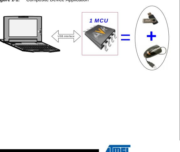
Adding to the flexibility given to the user with the Hot Plug & Play, supplying power from the bus, the automatic detection of the insertion and remove of the device and by providing different transfer modes, the USB allows the user to manage several USB applications using ONE device called “COMPOSITE DEVICE”.
The aim of this document is to describe how to start and implement a composite device application.
A familiarity with USB Software Library for AT90USBxxx Microcontrollers (Doc 7675, I n c l u d e d i n t h e C D - R O M & A t m e l w e b s i t e ) a n d t h e C D C s p e c i f i c a t i o n (http://www.usb.org) is assumed.
Figure 1-1. Composite Device Application
+
US B interface=
1 M C U
8-bit
Microcontrollers
Application Note
2
7805A–USB–08/08
AVR293
board)
2. AVR USB microcontroller
3. USB cable (Standard A to Mini B)
4. PC running on Windows® (2000, XP) with USB 1.1 or 2.0 host
Note: Another STK 52x and USB port are required if the PC has no RS232 interface.
3.
In system programming and Device Firmware Upgrade
To program the device you can use the following methods: • The JTAG interface using the JTAGICE MKII
• The SPI interface using the AVRISP MKII
• The USB interface thanks to the factory DFU bootloader and Flip software • The parallel programming using the STK500 or the STK600
Please refer to the hardware user guide of the board you are using (if you are using Atmel starter kit) to see how to program the device using one of these different methods.
Please refer to Flip(1) help content to see how to install the USB driver and program the device through the USB interface.
(1)Flip is a software provided by atmel to allow the user to program the AVR USB devices through the USB interface (No external hardware required) thanks to the factory DFU bootloader.
AVR293
4.
Quick Start
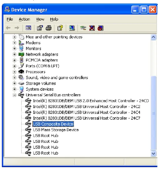
Once your device is programmed with hex file (depending on which composite device demo you are using), click on Start Application button on Flip or push the reset button from the used board to start the composite device demonstration. Check that your device is enumerated as compos-ite device (see Figure 6-1), then you can use the board as a mouse, removable disk and Generic HID (you may have less or more applications depending on which demo you are using) at the same time.
4
7805A–USB–08/08
AVR293
4.1
Composite Device
The purpose of the Composite Device demonstration is to show the user how to manage several USB applications using only one USB controller.
Depending on which demonstartion you are uisng, when you cannect your device to you PC, you will see two or more of below applications appear in your device manager, and you can use each application in stand alone mode:
– USB mouse: you can move the mouse pointer using the joystic or the buttons of youyr board
– USB Mass Storage (removable disk): a new removable disk will appear, and you can transfer file with the onboard dataflash of your board (or any other memory
depending on which board you are using)
– Generic HID device: please refer to the Generic HID application note: doc7599 J o y s t i c k
U S B C o n n e c t o r
AVR293
5.
Application Overview
To implement a Composite Device application, the user has to integrate several interfaces in his device (one for each application).
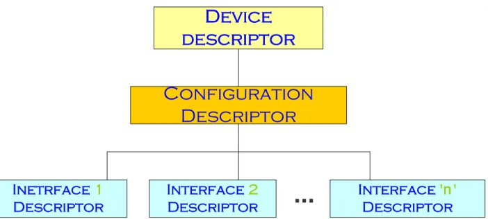
The figure below shows the descriptors structure:
Figure 5-1. Composite Device Overview
To add new interface to manage an adding application using the same controller, you have to modify the number of interfaces supported by the configuration descriptor, add the interface descriptor, the endpoint descriptors and the related specific requests management.
Device
descriptor
Configuration
Descriptor
Interface
'
n
'
Descriptor
Interface
2
Descriptor
Inetrface
1
Descriptor
...
6
7805A–USB–08/08
AVR293
refer to this document for more details).
To add new interface, the follwoing files have to be modified:
6.1
usb_descriptors.h
This file contains the definition of the descriptors’ parameters. You have to modify and add the following parameters when you want to customize one of our demo to build a composite device or add a new interface to a current composite device:
• Modify the VID/PID of the device descriptor. Each USB application must have its own and unique VID/PID:
// USB Device descriptor
#define USB_SPECIFICATION 0x0200
#define DEVICE_CLASS 0 // each configuration has its own class #define DEVICE_SUB_CLASS 0 // each configuration has its own sub-class
#define DEVICE_PROTOCOL 0 // each configuration has its own protocol
#define EP_CONTROL_LENGTH 64
#define VENDOR_ID VID_ATMEL #define PRODUCT_ID PID_MegaMS
#define RELEASE_NUMBER 0x1000 #define MAN_INDEX 0x01 #define PROD_INDEX 0x02 #define SN_INDEX 0x03 #define NB_CONFIGURATION 1
Note: The class, subclass and protocol parameter must be set to 0 in the device descriptor. Each inter-face will specify its own class/subclass/protocol parameter.
• Modify the number of interfaces supported by the configuration’s descriptor:
// USB Configuration descriptor
#define NB_INTERFACE N // Number of interfaces #define CONF_NB 1
#define CONF_INDEX 0
#define CONF_ATTRIBUTES USB_CONFIG_BUSPOWERED #define MAX_POWER 50 // 100 mA
• Add the descriptor of your new interafce. Please note that the first interface start with the number 0, the next one should be number 1 and so on. So, depending on how many interfaces you have in you application, this new one should be number (n+1). “n” is the number of the last interface.The example hereunder shows the interface’s descriptor of a Mass Storage application:
// USB Interface descriptor
#define INTERFACE_NB n+1 // Interface's number #define ALTERNATE 0
#define NB_ENDPOINT 2
AVR293
#define INTERFACE_SUB_CLASS MS_SUB_CLASS6 // SCSI transparent Command Set #define INTERFACE_PROTOCOL MS_PROTOCOL // Bulk-Only Transport
#define INTERFACE_INDEX 0
• Than, depending on the class you added with this new interface, you have to add the related endpoint descriptors with the correct transfer mode, maximum packet lenght... and you may need to declare specific descriptors (for example, the HID class requires a HID descriptor and a report descriptor adding to the endpoint descriptors)
• Once all descriptors are specified and the related parameters are defined, you have to add to the structure below:
typedef struct { S_usb_configuration_descriptor cfg; S_usb_interface_descriptor ifc0; S_usb_endpoint_descriptor ep1; S_usb_endpoint_descriptor ep2; S_usb_interface_descriptor ifc1; S_usb_endpoint_descriptor ep3; S_usb_endpoint_descriptor ep4; } S_usb_user_configuration_descriptor;
Now, you have to complete the usb_descriptors.c file with the new descriptors values. Please, see hereunder:
6.2
usb_descriptors.c
In this file, you have to add the new descriptors values in the correct order, as specified by the USB.
6.3
usb_specific_request.c
As Mentioned above, a new interface may require a specific requests management. These requests have to be manage by the usb_specific_request.c and specially the function usb_user_read_request(). A new functions may be added to this file to handle a specific tasks related to these specific requests.
This new interface has one or more endpoints. These endpoints has to be configured using the function usb_configure_endpoint() used by the function usb_user_endpoint_init().
These modifications will allow the device to enumerate as a composite device with the new class/subclass/protocol defined by the new interface. To use this interface you have now to add the application layer by creating an xxx_task.c to manage your application.
8
7805A–USB–08/08
AVR293
enough endpoints and DPRAM to handle the endpoints of all interfaces. • Some Operating Systems does not support the composite device by default.
9.
Related Documentation
• AVR USB Datasheet
Headquarters International Atmel Corporation 2325 Orchard Parkway San Jose, CA 95131 USA Tel: 1(408) 441-0311 Fax: 1(408) 487-2600 Atmel Asia Room 1219
Chinachem Golden Plaza 77 Mody Road Tsimshatsui East Kowloon Hong Kong Tel: (852) 2721-9778 Fax: (852) 2722-1369 Atmel Europe Le Krebs
8, Rue Jean-Pierre Timbaud BP 309 78054 Saint-Quentin-en-Yvelines Cedex France Tel: (33) 1-30-60-70-00 Fax: (33) 1-30-60-71-11 Atmel Japan 9F, Tonetsu Shinkawa Bldg. 1-24-8 Shinkawa Chuo-ku, Tokyo 104-0033 Japan Tel: (81) 3-3523-3551 Fax: (81) 3-3523-7581 Product Contact Web Site www.atmel.com Technical Support [email protected] Sales Contact www.atmel.com/contacts Literature Requests www.atmel.com/literature