Reference Architecture-Based Design
Citrix XenDesktop Built on FlexPod
Citrix XenDesktop Using Citrix XenServer,
Cisco Unified Computing System, Nexus 5000, and
NetApp Storage
Cisco Validated Design
Contents
1.0 Goal ... 5
1.1 Audience ... 5
1.2 Objectives ... 5
2.0 Summary of Main Findings ... 6
3.0 Infrastructure Components ... 7
3.1 Cisco Unified Computing System ... 7
3.2 Cisco Unified Computing System Components... 8
3.2.1 Fabric Interconnect ... 8
3.2.2 Cisco UCS 2100 Series Fabric Extenders ... 9
3.2.3 Cisco UCS Chassis ... 10
3.2.4 Cisco UCS B200 M1 Blade Server ... 11
3.2.5 Cisco UCS B250 M1 Blade Server ... 11
3.2.6 Intel Xeon 5500 Series Processor ... 11
3.2.7 Intel Xeon 5600 Series Processor ... 12
3.2.8 Cisco UCS B200 M2 Blade Server ... 13
3.2.9 Cisco UCS B250 M2 Extended Memory Blade Server ... 13
3.2.10 Cisco UCS B440 M1 High-Performance Blade Server ... 14
3.2.11 Cisco UCS M71KR-Q QLogic Converged Network Adapter ... 14
3.2.12 Cisco Extended Memory Architecture ... 15
3.2.13 Cisco UCS C-Series Rack-Mount Servers ... 16
3.3 Citrix XenDesktop ... 17
3.3.1 Citrix FlexCast Technology ... 17
3.3.2 Citrix XenServer ... 17
3.3.3 High-Definition User Experience (HDX)Technology ... 18
3.3.4 Citrix XenDesktop Architecture Overview ... 18
3.3.5 Citrix XenDesktop Hosted VDI Overview ... 18
3.3.5 Citrix XenDesktop Hosted Shared Desktops Overview ... 22
3.3.6 Citrix XenDesktop Hosted Shared Desktops ... 24
3.3.7 Citrix XenApp Virtual Applications ... 25
3.3.8 General Citrix XD Advantages and Value Proposition ... 25
3.4 NetApp Storage Solution and Components ... 27
3.4.1 Single Scalable Unified Architecture ... 27
3.4.2 Storage Efficiency ... 27
3.4.3 Thin Provisioning ... 28
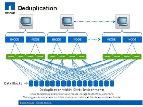
3.4.4 NetApp Deduplication ... 29
3.4.5 Performance ... 30
3.4.6 Transparent Storage Cache Sharing ... 30
3.4.7 NetApp Flash Cache and PAM ... 31
3.4.8 NetApp Write Optimization ... 31
3.4.9 Flexible Volumes and Aggregates... 31
3.4.10 Operational Agility ... 31
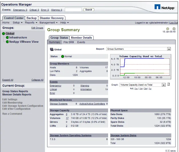
3.4.11 NetApp Operations Manager... 32
3.4.12 Data Protection ... 33
3.4.12.1 RAID-DP ... 33
3.4.12.2 Backup and Recovery ... 33
3.4.13 Storage Sizing Best Practices ... 34
3.4.13.1 Gather Essential Solution Requirements ... 34
3.4.13.2 Performance-Based and Capacity-Based Storage Estimation Processes ... 35
3.4.13.3 Getting Recommendations on Storage System Physical and Logical Configuration ... 35
3.4.14 Storage Architecture Best Practices ... 36
3.4.15 Storage System Configuration Best Practices ... 36
3.4.16 Building a Resilient Storage Architecture ... 36
3.4.17 Top Resiliency Practices ... 37
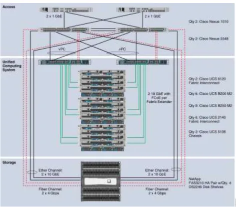
3.5 FlexPod Technical Overview ... 38
3.5.1 Audience ... 39
3.5.2 FlexPod Architecture ... 39
3.5.3 FlexPod Market Overview ... 40
3.5.3.1 The Challenge ... 40
3.5.3.2 The Solution ... 40
3.5.3.3 NetApp: Unified Architecture for Extreme Efficiencies... 41
3.6 Cisco Networking Infrastructure ... 41
3.6.1 Cisco Nexus 5548 28-Port Switch ... 41
3.6.2 Cisco Nexus 5500 Series Feature Highlights ... 42
3.6.2.1 Features and Benefits ... 42
3.6.2.2 10 Gigabit Ethernet and Unified Fabric Features ... 42
3.6.2.3 Low Latency ... 42
3.7 Microsoft Windows 7 ... 42
3.7.1 Microsoft Windows 7 Image Creation and Provisioning ... 43
3.7.1.1 Create Windows 7 Virtual Machine and Install Standard Software ... 44
3.7.1.2 Tuning Microsoft Windows 7 Image for VDI ... 44
3.7.1.3 Provisioning Services (PVS) vDisk Creation ... 45
3.7.1.4 Install and Configure Additional Software Components ... 47
3.7.1.5 Add 3-GB Write Cache .VHD to vDisk Image ... 47
4.0 Architecture and Design of Citrix XenDesktops on Cisco Unified Computing System and NetApp Storage ... 50
4.1 Design Fundamentals ... 50
4.1.1 Hosted Shared Design Fundamentals ... 51
4.1.1.1 Citrix XenApp Policies ... 51
4.1.1.2 Worker Groups ... 51
4.1.1.3 Load Managed Groups ... 51
4.1.2 Hosted VDI Design Fundamentals ... 51
4.1.2.1 Hypervisor Selection ... 52
4.1.2.2 Provisioning Services ... 52
4.1.3 Designing a Citrix XenDesktop Deployment ... 53
5.0 Solution Validation ... 54
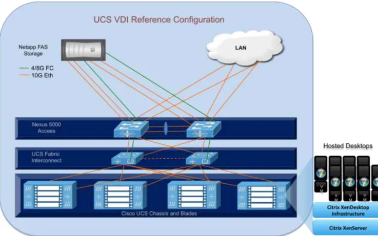
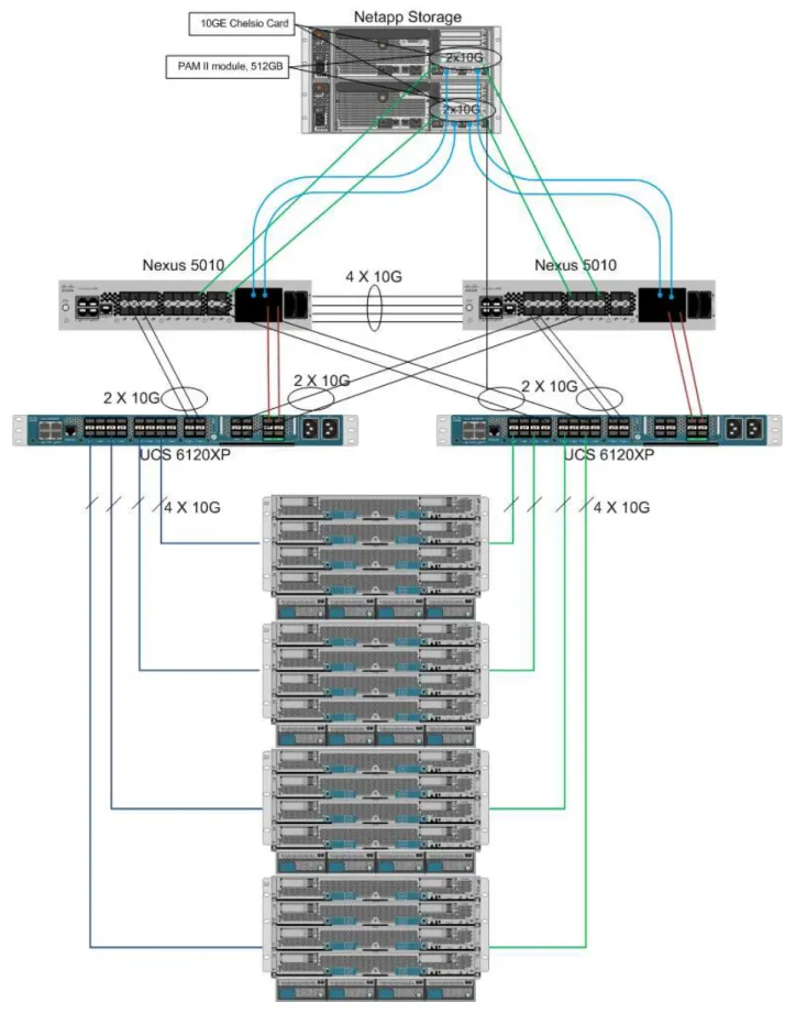
5.1 Configuration Topology for Scalability of Citrix XenDesktops on Cisco Unified System and NetApp Storage ... 54
5.2 Cisco Unified Computing System Configuration... 56
5.2.1 QOS and COS in Cisco Unified Computing System ... 63
5.2.2 System Class Configuration ... 63
5.2.3 Cisco UCS System Class Configuration ... 63
5.3 Citrix XenDesktop Configuration ... 66
5.3.1 Citrix XenDesktop Desktop Delivery Controller (DDC) ... 68
5.3.2 Farm Configuration ... 68
5.3.3 Provisioning Services Configuration ... 68
5.3.4 Storage Configuration for the Citrix XenServer Hosting the Virtual Desktop Virtual Machine .. 69
5.3.5 Citrix Provisioning Services ... 70
5.3.6 Citrix Provisioning Server (PVS) for use with Standard Desktops ... 70
5.3.7 Hosted Shared Desktops Environment Configuration ... 73
5.4 LAN Configuration ... 74
5.5 SAN Configuration ... 77
5.5.1 Boot From SAN ... 79
5.5.2 Configuring Boot From SAN on the Cisco Unified Computing System ... 80
5.5.3 SAN Configuration ... 85
5.5.4 Cisco UCS Manager Configuration ... 86
5.6 NetApp Storage Configuration ... 88
5.6.1 Example of a NetApp NFS Volume Configuration ... 90
5.6.2 NetApp Deduplication in Practice ... 95
5.7.1 Cisco UCS Configuration for Citrix XenServer Installation ... 97
5.7.2 VLAN Configuration for XenServer Host Management Interfaces ... 98
5.8 OS Installation ... 98
5.8.1 XenServer Networking ... 100
5.9 XenServer Resource Pools ... 101
6.0 Test Setup and Configurations ... 104
6.1 Cisco UCS Test Configuration for Single-Server Scalability Test Setup ... 104
6.2 Cisco UCS Configuration for Two-Chassis Test... 105
6.3 Cisco UCS Configuration for Four-Chassis Test ... 106
6.4 Testing Methodology ... 107
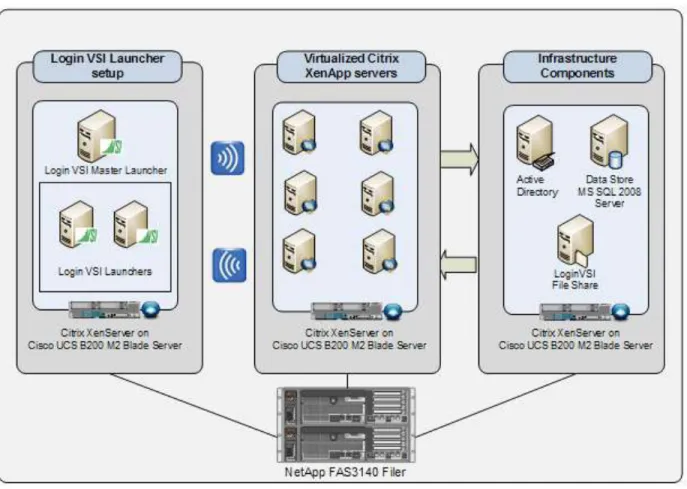
6.4.1 Load Generation ... 107
6.4.2 User Workload Simulation – Login VSI from Login Consultants ... 107
6.4.3 Success Criteria ... 108
6.4.3.1 Login VSI Corrected Optimal Performance Index (COPI) ... 108
6.4.3.2 Login VSI Max ... 108
7.0 Test Results ... 110
7.1 Citrix XenDesktop Hosted VDI Test Results ... 110
7.1.1 Single Cisco UCS Blade Server Validation ... 110
7.1.2 Two Cisco UCS Blade Chassis Validation ... 111
7.1.3 Four Cisco UCS Blade Chassis Validation ... 112
7.1.3.1 Storage Data for Four-Chassis Validation ... 122
7.2 Citrix XenDesktop with XenApp Hosted Shared Test Results ... 125
8.0 Scalability Considerations and Guidelines ... 130
8.1 Cisco UCS System Configuration ... 130
9.0 Acknowledgments ... 131
10.0 References ... 132
1.0 Goal
The goal of this document is to provide architectural design and sizing guidelines for the hosting of small-to-large scale Citrix XenDesktop 4 and Citrix XenApp environments in a Cisco Data Center Fabric environment. This document presents one of a portfolio of design documents intended to simplify, ease and accelerate the deployment of Cisco VXI Desktop Virtualization Solutions. This specific document reports the results of a study evaluating the scalability of the Citrix XenDesktop environment on Cisco Unified Computing System™ (UCS) B-Series Blade Servers connected to NetApp Storage arrays. This document reflects the best practice recommendations and sizing guidelines for large-scale customer deployments of XenDesktops in FlexPod environments.
1.1 Audience
This document is intended to assist solution architects, sales engineers, field engineers and consultants in planning, design, and deployment of Citrix XenDesktop hosted desktop virtualization solutions on the Cisco Unified Computing System. This document assumes that the reader has an architectural understanding of the Cisco Unified Computing System, Citrix desktop software, NetApp storage system, and related software.
1.2 Objectives
This document is intended to articulate the design considerations and validation efforts required to design and deploy Citrix XenDesktops on the Cisco Unified Computing System with NetApp storage running in a virtualized environment on top of Citrix XenServer. The desktop virtualization hosting solution described in this paper forms a core building block of the Cisco Virtualization Experience Infrastructure (VXI) solution that delivers an end-to-end data center, network and end point solutions for desktop virtualization and voice and video communications.
2.0 Summary of Main Findings
The hosting of Citrix XenDesktop Hosted Virtual Desktops (VDI) and Hosted Shared Virtual Desktops models and FlexCast with Citrix XenServer Hypervisors on Cisco UCS B-Series Blade Servers and NetApp storage were successfully validated.
The Cisco UCS B250 M2 Extended Memory Blade Servers offer an optimal memory configuration that allows virtual desktop hosting servers to use the full CPU capabilities of the servers. The 192 GB of memory allowed a high density of desktop sessions per Cisco UCS B250 M2 Extended Memory Blade Servers while offering 1.5 GB of memory to be allocated per desktop-based virtual machine. We were able to scale to 110 Microsoft Windows 7 desktops while running a knowledge worker load.
The validated environment consisted of a completely virtualized infrastructure with virtual machines hosted by Citrix XenServer. All the virtual desktop and supporting infrastructure components including Active Directory, Citrix Provisioning Server, and the Citrix XenDesktop Desktop Delivery Controllers were hosted in a virtual machine environment on Citrix XenServer 5.6.
The tested design showed linear scalability when expanding from 1 server to 16 servers. The performance testing showed that the same user desktop experience and response times were achieved with 110 desktops running on 1 server as with 1760 desktops running on 16 servers.
The integrated management model and rapid provisioning capabilities of Cisco UCS Manager makes it easy for scaling the number of desktops from small pilots on a single UCS chassis to very large organization-wide deployments running on tens of chassis.
The testing validates that the 10Gbps Unified Fabric provides a high performance; scalable infrastructure and offers deterministic performance with respect to user response times during the load and stress testing.
The testing validates that the tested reference architecture can scale linearly from 1 chassis to 4 chassis and beyond without making any changes to the design or infrastructure components. This also requires the proper backend storage scaling as provided by NetApp storage.
Desktop virtual machine ―Boot-up‖ or ―Logon‖ Storms (from rapid concurrent or simultaneous user logons) need to be considered in the server and storage design as they have largest substantial scalability impact on this solution as well as VDI environments in general. The reference architecture represented in this document was able to handle the additional stresses presented by the most extreme boot-up and log-on storm conditions.
3.0 Infrastructure Components
The following sections detail the infrastructure components used in this configuration.
3.1 Cisco Unified Computing System
The Cisco Unified Computing System is a next-generation data center platform that unites compute, network, storage access, and virtualization into a cohesive system designed to reduce total cost of ownership (TCO) and increase business agility. The Cisco Unified Computing System server portfolio consists of the Blade Server platform, B-Series and the C-Series Rack Mount platform. We chose the Cisco UCS B-Series Blade Server platform for this study. The system integrates a low-latency, lossless 10 Gigabit Ethernet unified network fabric with enterprise-class, x86-architecture servers. The system is an integrated, scalable, multi-chassis platform in which all resources participate in a unified management domain.
The main system components include:
Compute—the system is based on an entirely new class of computing system that incorporates blade servers based on Intel Xeon 5500 Series Processors. The Cisco UCS blade servers offer patented Cisco Extended Memory Technology to support applications with large datasets and allow more virtual machines per server. Network—the system is integrated onto a low-latency, lossless, 10-Gbps unified network fabric. This network foundation consolidates what today are three separate networks: LANs, SANs, and high-performance computing networks. The unified fabric lowers costs by reducing the number of network adapters, switches, and cables, and by decreasing power and cooling requirements.
Virtualization—the system unleashes the full potential of virtualization by enhancing the scalability, performance, and operational control of virtual environments. Cisco security, policy enforcement, and diagnostic features are now extended into virtualized environments to better support changing business and IT requirements.
Storage access—the system provides consolidated access to both SAN storage and Network Attached Storage (NAS) over the unified fabric. Unifying storage access means that the Cisco Unified Computing System can access storage over Ethernet, Fibre Channel, Fibre Channel over Ethernet (FCoE), and iSCSI, providing customers with choice and investment protection. In addition, administrators can pre-assign storage-access policies for system connectivity to storage resources, simplifying storage connectivity and management while helping increase productivity.
Management—the system uniquely integrates all the system components, enabling the entire solution to be managed as a single entity through the Cisco UCS Manager software. The Cisco UCS Manager provides an intuitive graphical user interface (GUI), a command-line interface (CLI), and a robust application programming interface (API) to manage all system configuration and operations. The Cisco UCS Manager helps increase IT staff productivity, enabling storage, network, and server administrators to collaborate on defining service profiles for applications. Service profiles are logical representations of desired physical configurations and infrastructure policies. They help automate provisioning and increase business agility, allowing data center managers to provision resources in minutes instead of days.
Working as a single, cohesive system, these components unify technology in the data center. They represent a radical simplification in comparison to traditional systems, helping simplify data center operations while reducing power and cooling requirements. The system amplifies IT agility for improved business outcomes. The Cisco Unified Computing System components illustrated in Figure 1 include, from left to right, fabric interconnects, blade server chassis, blade servers, and in the foreground, fabric extenders and network adapters.
Figure 1. Cisco Unified Computing System
3.2 Cisco Unified Computing System Components
3.2.1 Fabric Interconnect
The Cisco UCS 6100 Series Fabric Interconnects are a core part of the Cisco Unified Computing System, providing both network connectivity and management capabilities for the system (Figure 2). The Cisco UCS 6100 Series offers line-rate, low-latency, lossless 10 Gigabit Ethernet and FCoE functions.
The Cisco UCS 6100 Series provides the management and communication backbone for the Cisco UCS B-Series Blade Servers and Cisco UCS 5100 Series Blade Server Chassis. All chassis, and therefore all blades, attached to the Cisco UCS 6100 Series Fabric Interconnects become part of a single, highly available management domain. In addition, by supporting unified fabric, the Cisco UCS 6100 Series provides both the LAN and SAN connectivity for all blades within its domain.
From a networking perspective, the Cisco UCS 6100 Series uses a cut-through architecture, supporting deterministic, low-latency, line-rate 10 Gigabit Ethernet on all ports, independent of packet size and enabled services. The product family supports Cisco low-latency, lossless 10 Gigabit Ethernet unified network fabric capabilities, which increase the reliability, efficiency, and scalability of Ethernet networks. The fabric interconnect supports multiple traffic classes over a lossless Ethernet fabric from the blade through the interconnect. Significant TCO savings come from an FCoE-optimized server design in which network interface cards (NICs), host bus adapters (HBAs), cables, and switches can be consolidated.
The Cisco UCS 6100 Series is also built to consolidate LAN and SAN traffic onto a single unified fabric, saving the capital and operating expenses associated with multiple parallel networks, different types of adapter cards, switching infrastructure, and cabling within racks. Fibre Channel expansion modules in the interconnect support direct connections from the Cisco Unified Computing System to existing native Fibre Channel SANs. The capability to connect FCoE to native Fibre Channel protects existing storage system investments while dramatically simplifying in-rack cabling.
Figure 2. Cisco UCS 6120XP 20-Port Fabric Interconnect (Top) and Cisco UCS 6140XP 40-Port Fabric Interconnect
The Cisco UCS 6100 Series is equipped to support the following module options:
● Ethernet module that provides 6 ports of 10 Gigabit Ethernet using the SFP+ interface
● Fibre Channel plus Ethernet module that provides 4 ports of 10 Gigabit Ethernet using the SFP+ interface; and 4 ports of 1/2/4-Gbps native Fibre Channel connectivity using the SFP interface
● Fibre Channel module that provides 8 ports of 1/2/4-Gbps native Fibre Channel using the SFP interface for transparent connectivity with existing Fibre Channel networks
● Fibre Channel module that provides 6 ports of 1/2/4/8-Gbps native Fibre Channel using the SFP or SFP+ interface for transparent connectivity with existing Fibre Channel networks
Figure 3. From left to right: 8-Port 1/2/4-Gbps Native Fibre Channel Expansion Module; 4-Port Fibre Channel plus 4-Port 10
3.2.2 Cisco UCS 2100 Series Fabric Extenders
The Cisco UCS 2100 Series Fabric Extenders bring the unified fabric into the blade server enclosure, providing 10 Gigabit Ethernet connections between blade servers and the fabric interconnect, simplifying diagnostics, cabling, and management.
The Cisco UCS 2100 Series extends the I/O fabric between the Cisco UCS 6100 Series Fabric Interconnects and the Cisco UCS 5100 Series Blade Server Chassis, enabling a lossless and deterministic FCoE fabric to connect all blades and chassis together. Since the fabric extender is similar to a distributed line card, it does not do any switching and is managed as an extension of the fabric interconnects. This approach removes switching from the chassis, reducing overall infrastructure complexity and enabling the Cisco Unified Computing System to scale to many chassis without multiplying the number of switches needed, reducing TCO and allowing all chassis to be managed as a single, highly available management domain.
The Cisco 2100 Series also manages the chassis environment (the power supply and fans as well as the blades) in conjunction with the fabric interconnect. Therefore, separate chassis management modules are not required. The Cisco UCS 2100 Series Fabric Extenders fit into the back of the Cisco UCS 5100 Series chassis. Each Cisco UCS 5100 Series chassis can support up to two fabric extenders, enabling increased capacity as well as redundancy.
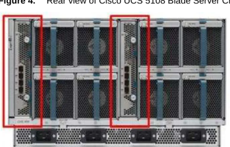
Figure 4. Rear view of Cisco UCS 5108 Blade Server Chassis with two Cisco UCS 2104XP Fabric Extenders
The Cisco UCS 2104XP Fabric Extender has four 10 Gigabit Ethernet, FCoE-capable, Small Form-Factor Pluggable Plus (SFP+) ports that connect the blade chassis to the fabric interconnect. Each Cisco UCS 2104XP has eight 10 Gigabit Ethernet ports connected through the midplane to each half-width slot in the chassis. Typically configured in pairs for redundancy, two fabric extenders provide up to 80 Gbps of I/O to the chassis.
Figure 5. Cisco UCS 2104XP Fabric Extender
3.2.3 Cisco UCS Chassis
The Cisco UCS 5100 Series Blade Server Chassis is a crucial building block of the Cisco Unified Computing System, delivering a scalable and flexible blade server chassis for today's and tomorrow's data center while helping reduce TCO.
Cisco's first blade server chassis offering, the Cisco UCS 5108 Blade Server Chassis, is six rack units (6RU) high and can mount in an industry-standard 19-inch rack. A chassis can house up to eight half-width Cisco UCS B-Series Blade Servers and can accommodate both half- and full-width blade form factors.
Four single-phase, hot-swappable power supplies are accessible from the front of the chassis. These power supplies are 92 percent efficient and can be configured to support non-redundant, N+ 1 redundant and grid-redundant configuration. The rear of the chassis contains eight hot-swappable fans, four power connectors (one per power supply), and two I/O bays for Cisco UCS 2104XP Fabric Extenders.
A passive mid-plane provides up to 20 Gbps of I/O bandwidth per server slot and up to 40 Gbps of I/O bandwidth for two slots. The chassis is capable of supporting future 40 Gigabit Ethernet standards.
3.2.4 Cisco UCS B200 M1 Blade Server
The Cisco UCS B200 M1 Blade Server is a half-width, two-socket blade server. The system uses two Intel Xeon 5500 Series Processors, up to 96 GB of DDR3 memory, two optional hot-swappable small form factor (SFF) serial attached SCSI (SAS) disk drives, and a single mezzanine connector for up to 20 Gbps of I/O throughput. The server balances simplicity, performance, and density for production-level virtualization and other mainstream data center workloads.
Figure 7. Cisco UCS B200 M1 Blade Server
3.2.5 Cisco UCS B250 M1 Blade Server
The Cisco UCS B250 M1 Extended Memory Blade Server is a full-width, two-socket blade server featuring Cisco Extended Memory Technology. The system supports two Intel Xeon 5500 Series processors, up to 384 GB of DDR3 memory, two optional SFF SAS disk drives, and two mezzanine connections for up to 40 Gbps of I/O throughput. The server increases performance and capacity for demanding virtualization and large-data-set workloads with greater memory capacity and throughput.
Figure 8. Cisco UCS B250 M1 Extended Memory Blade Server
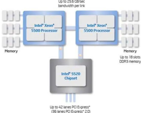
3.2.6 Intel Xeon 5500 Series Processor
With innovative technologies that boost performance, energy efficiency, and virtualization flexibility, two-processor platforms based on the Intel Xeon 5500 Series Processor make it easier to deliver more business services within existing data center facilities. Data center efficiency starts at the core – with energy-efficient processors and features that help you get the most out of each rack. With a unique combination of performance and energy-efficiency features plus flexible virtualization, the Intel Xeon 5500 Series Processor offers an effective antidote to data center sprawl and improves business competitiveness. The combination of Intel Turbo Boost Technology and Intel Hyper-Threading Technology delivers optimal performance for each enterprise application, and Intel QuickPath Technology dramatically increases application performance and throughput for bandwidth-intensive applications.
Greater per-server performance means that you can do more with fewer servers and potentially save significantly on operating costs. Intel Intelligent Power Technology works alongside these new performance features to deliver better performance with lower power consumption at all operating points, achieving the best available performance/watt. High-performance 95-watt, standard 80-watt and low-power 60-watt versions enable high-density deployments in both rack and blade form factors.
Intel VT with Intel FlexMigration and Intel FlexPriority also gives IT more choice in managing and allocating virtualized workloads across new and existing platforms. Intel Turbo Boost Technology plus hardware assists from Intel VT improves performance for applications running in virtual machines. Intel VT FlexMigration, in combination with virtualization management software, can help IT to conserve power, rebalance workloads and reduce energy consumption.
Figure 9. Intel Xeon 5500 Series Processor
3.2.7 Intel Xeon 5600 Series Processor
As data centers reach the upper limits of their power and cooling capacity, efficiency has become the focus of extending the life of existing data centers and designing new ones. As part of these efforts, IT needs to refresh existing infrastructure with standard enterprise servers that deliver more performance and scalability, more efficiently. The Intel Xeon 5600 Series Processor automatically regulates power consumption and intelligently adjusts server performance according to your application needs, both energy efficiency and performance. The secret to this compelling combination is Intel‘s new 32nm Xeon microarchitecture. Featuring Intel Intelligent Power Technology that automatically shifts the CPU and memory into the lowest available power state, while delivering the performance you need, the Intel Xeon 5600 Series Processor with Intel Micro-architecture Xeon delivers the same performance as previous-generation servers but uses up to 30 percent less power. You can achieve up to a 93 percent reduction in energy costs when consolidating your single-core infrastructure with a new infrastructure built on Intel Xeon 5600 Series Processor.
This groundbreaking intelligent server technology features:
● Intel‘s new 32nm Microarchitecture Xeon built with second-generation high-k and metal gate transistor technology.
● Intelligent Performance that automatically optimizes performance to fit business and application requirements and delivers up to 60 percent more performance per watt than Intel Xeon 5500 Series Processor.
● Automated Energy Efficiency that scales energy usage to the workload to achieve optimal performance/watt and with new 40 Watt options and lower power DDR3 memory, you can lower your energy costs even further.
● Flexible virtualization that offers best-in-class performance and manageability in virtualized environments to improve IT infrastructure and enable up to 15:1 consolidation over two socket, single-core servers. New standard enterprise servers and workstations built with this new generation of Intel process technology
offer an unprecedented opportunity to dramatically advance the efficiency of IT infrastructure and provide unmatched business capabilities.
Figure 10. Intel Xeon 5600 Series Processor
3.2.8 Cisco UCS B200 M2 Blade Server
The Cisco UCS B200 M2 Blade Server is a half-width, two-socket blade server. The system uses two Intel Xeon 5600 Series Processors, up to 96 GB of DDR3 memory, two optional hot-swappable small form factor (SFF) serial attached SCSI (SAS) disk drives, and a single mezzanine connector for up to 20 Gbps of I/O throughput. The server balances simplicity, performance, and density for production-level virtualization and other mainstream data center workloads.
Figure 11. Cisco UCS B200 M2 Blade Server
3.2.9 Cisco UCS B250 M2 Extended Memory Blade Server
The Cisco UCS B250 M2 Extended Memory Blade Server is a full-width, two-socket blade server featuring Cisco Extended Memory Technology. The system supports two Intel Xeon 5600 Series Processors, up to 384 GB of DDR3 memory, two optional SFF SAS disk drives, and two mezzanine connections for up to 40 Gbps of I/O throughput. The server increases performance and capacity for demanding virtualization and large-data-set workloads with greater memory capacity and throughput.
Figure 12. Cisco UCS B250 M2 Extended Memory Blade Server
3.2.10 Cisco UCS B440 M1 High-Performance Blade Server
The Cisco UCS B440 M1 High-Performance Blade Server is a full-width, 4-socket system. Two or four Intel Xeon 7500 Series Processors with intelligent performance that automatically adapts to the diverse needs of a virtualized environment and offers advanced reliability for mission-critical workloads. It supports 32 dual in-line memory module (DIMM) slots and up to 256 GB at 1333 MHz based on Samsung's 40 nanometer class (DDR3) technology. There is four optional front-accessible, hot-swappable Small Form-Factor Pluggable (SFFP) drives and an LSI SAS2108 RAID Controller. The Cisco UCS B440 M1 blade server can accommodate two dual-port mezzanine cards for up to 40 Gbps I/O per blade. Options include a Cisco UCS M81KR Virtual Interface Card (VIC) or converged network adapter (Emulex or QLogic compatible).
Figure 13. Cisco UCS B440 M1 Blade Server
3.2.11 Cisco UCS M71KR-Q QLogic Converged Network Adapter
The Cisco UCS M71KR-Q QLogic Converged Network Adapter (CNA) is a QLogic-based FCoE mezzanine card that provides connectivity for Cisco UCS B-Series Blade Servers in the Cisco Unified Computing System.
Designed specifically for the Cisco UCS blade servers, the adapter provides a dual-port connection to the midplane of the blade server chassis. The Cisco UCS M71KR-Q uses an Intel 82598 10 Gigabit Ethernet controller for network traffic and a QLogic 4-Gbps Fibre Channel controller for Fibre Channel traffic, all on the same mezzanine card. The Cisco UCS M71KR-Q presents two discrete Fibre Channel host bus adapter (HBA) ports and two Ethernet network ports to the operating system.
The Cisco UCS M71KR-Q provides both 10 Gigabit Ethernet and 4-Gbps Fibre Channel functions using drivers from QLogic, providing:
● Risk mitigation through compatibility with current QLogic adapter-based SAN environments and drivers ● Reduced TCO through consolidation of LAN and SAN traffic over the same mezzanine card and fabric,
reducing the overall number of network interface cards (NICs), HBAs, cables, and switches ● Integrated management with Cisco UCS Manager
Figure 15. Cisco UCS M71KR-Q Architecture
3.2.12 Cisco Extended Memory Architecture
Modern CPUs with built-in memory controllers support a limited number of memory channels and slots per CPU. The need for virtualization software to run multiple OS instances demands large amounts of memory, and that, combined with the fact that CPU performance is outstripping memory performance, can lead to memory bottlenecks. Even some traditional non-virtualized applications demand large amounts of main memory: database management system performance can be improved dramatically by caching database tables in memory, and modeling and simulation software can benefit from caching more of the problem state in memory.
To obtain a larger memory footprint, most IT organizations are forced to upgrade to larger, more expensive, four-socket servers. CPUs that can support four-four-socket configurations are typically more expensive, require more power, and entail higher licensing costs. Cisco Extended Memory Technology expands the capabilities of CPU-based memory controllers by logically changing the geometry of main memory while still using standard DDR3 memory. This technology makes every four DIMM slots in the expanded memory blade server appear to the CPU‘s memory controller as a single DIMM that is four times the size (Figure 16). For example, using standard DDR3 DIMMs, the technology makes four 8-GB DIMMS appear as a single 32-GB DIMM.
This patented technology allows the CPU to access more industry-standard memory than ever before in a two-socket server:
● For memory-intensive environments, data centers can better balance the ratio of CPU power to memory and install larger amounts of memory without having the expense and energy waste of moving to four-socket servers simply to have a larger memory capacity. With a larger main-memory footprint, CPU
utilization can improve because of fewer disk waits on page-in and other I/O operations, making more effective use of capital investments and more conservative use of energy.
● For environments that need significant amounts of main memory but which do not need a full 384 GB, smaller-sized DIMMs can be used in place of 8-GB DIMMs, with resulting cost savings: two 4-GB DIMMS are typically less expensive than one 8-GB DIMM.
Figure 16. Cisco Extended Memory Architecture
3.2.13 Cisco UCS C-Series Rack-Mount Servers
The Cisco UCS C-Series Rack-Mount Servers (Figure 17) extend the Cisco Unified Computing System innovations to a rack-mount form factor, including a standards-based unified network fabric, Cisco VN-Link virtualization support, and Cisco Extended Memory Technology. Designed to operate both in standalone environments and as part of the Cisco Unified Computing System, these servers enable organizations to deploy systems incrementally—using as many or as few servers as needed—on a schedule that best meets the organization‘s timing and budget. Cisco UCS C-Series servers offer investment protection through the capability to deploy them either as standalone servers in heterogeneous data centers or as part of the Cisco Unified Computing System.
Although this study was carried out on the Cisco UCS B-Series Blade Servers, the C-Series Rack-Mount Servers extend the same benefits to customers. Future desktop virtualization studies are planned on this server platform.
3.3 Citrix XenDesktop
Citrix XenDesktop is a desktop virtualization solution that delivers Windows desktops as an on-demand service to any user, anywhere. With FlexCast™ delivery technology, XenDesktop can quickly and securely deliver individual applications or complete desktops to the entire enterprise, whether they are task workers, knowledge workers or mobile workers. Users now have the flexibility to access their desktop on any device, anytime, with a high-definition user experience. With XenDesktop, IT can manage single instances of each OS, application and user profile and dynamically assemble them to increase business agility and greatly simplify desktop management. XenDesktop‘s open architecture enables customers to easily adopt desktop virtualization using any hypervisor, storage or management infrastructure.
3.3.1 Citrix FlexCast Technology
XenDesktop FlexCast is an intelligent delivery technology that recognizes the user, device, and network, and delivers the correct virtual desktop and applications specifically tailored to meet the performance, security, and flexibility requirements of the user scenario. FlexCast for Desktops delivers any type of virtual desktop to any device—and can change this mix at any time. FlexCast for Apps delivers any type of virtual applications to any device. The FlexCast delivery technologies can be broken down into the following categories:
● Hosted shared desktops provide a locked-down, streamlined and standardized environment with a core set of applications, ideally suited for task workers where personalization is not required—or appropriate. ● Hosted virtual machine–based desktops (VDI) offer a personalized Windows desktop experience for office
workers that can be securely delivered over any network to any device.
● Streamed VHD Desktops use the local processing power of rich clients, while providing centralized single-image management of the desktop. These types of desktops are often used in computer labs and training facilities, and when users require local processing for certain applications or peripherals,
● Local virtual machine desktops extend the benefits of virtual desktops to mobile workers who need to use their laptops offline.
● FlexCast for Apps allows any Microsoft Windows application to be centralized and managed in the datacenter, hosted either on multi-user terminal servers or virtual machines, and instantly delivered as a service to physical and virtual desktops. Optimized for each user device, network and location, applications are delivered through a high-speed protocol for use while connected or streamed through Citrix application virtualization or Microsoft App-V directly to the endpoint for use when offline.
A complete overview of the FlexCast technology can be found on Citrix.com, but for the purposes of the testing and validation represented in this paper only the Hosted VDI and Hosted Shared models were validated on the Cisco UCS hardware in conjunction with NetApp storage solutions. The Hosted Shared and Hosted VDI models provide a low-cost virtual desktop delivery solution that uses the power of existing PC resources to help customers get started with desktop virtualization.
3.3.2 Citrix XenServer
In addition to the virtual desktop delivery options available with FlexCast, XenDesktop was intentionally designed to be hypervisor agnostic and therefore provide a choice when selecting a hypervisor to host virtual machine-based desktops. The open architecture of XenDesktop can utilize Citrix XenServer, Microsoft Hyper-V, and VMware vSphere hypervisors for the hosting virtual desktop infrastructure. For the purposes of the testing and validation represented in this paper only the Citrix XenServer bare-metal hypervisor was utilized to host virtual desktops.
Citrix XenServer is an enterprise-ready, cloud-proven virtualization platform with all the capabilities needed to create and manage a virtual infrastructure at half the cost of other solutions. Organizations of any size can install the free XenServer in less than ten minutes to virtualize even the most demanding workloads and automate management processes, which increases IT flexibility and agility, and lowers costs. To add a rich set of
management and automation capabilities designed to help customers create a virtual computing center, simply upgrade to one of the enhanced versions of XenServer.
3.3.3 High-Definition User Experience (HDX)Technology
Citrix has been perfecting the virtual application delivery technology for more than two decades. These High-Definition User Experience (HDX) technologies include software and hardware products, an advanced delivery protocol and intelligent algorithms used to optimize end-to-end system performance. Citrix XenDesktop incorporates the HDX technology to provide the most complete solution for high definition desktop and application virtualization on any device over any network. Citrix HDX is the only viable solution on the market for providing high definition multimedia content and graphics-intensive applications over the WAN, allowing businesses to utilize employee talent in more geographies while protecting intellectual property within the datacenter. HDX technology provides network and performance optimizations to deliver the best user experience over any network, including low bandwidth and high latency WAN connections. These user experience enhancements balance performance with low bandwidth–anything else becomes impractical to use and scale.
3.3.4 Citrix XenDesktop Architecture Overview
The Citrix XenDesktop Hosted Shared and Hosted VDI FlexCast Delivery Technologies can deliver different types of virtual desktops based on the performance, security and flexibility requirements of each individual user. Although the two desktop delivery models use similar components, the over architecture is distinctly different.
3.3.5 Citrix XenDesktop Hosted VDI Overview
Hosted VDI uses a hypervisor to host all the desktops in the data center. Hosted VDI desktops can either be pooled or assigned. Pooled virtual desktops use Citrix Provisioning Services to stream a standard desktop image to each desktop instance upon boot-up therefore the desktop is always reverted back to its clean, original state. Citrix Provisioning Services enables you to stream a single desktop image to create multiple virtual desktops on one or more hypervisors in a data center. This feature greatly reduces the amount of storage required compared to other methods of creating virtual desktops.
The high-level components of a Citrix XenDesktop architecture utilizing the Hosted VDI model for desktop delivery are shown in Figure 18:
Figure 18. Citrix XenDesktop on XenServer Architecture
● Web Interface: Web Interface provides the user interface to the XenDesktop environment. Web Interface brokers user authentication, enumerates the available desktops and, upon launch, delivers an .ica file to the Citrix Receiver on the user‘s local device to initiate a connection. Because Web Interface is a critical component, redundant servers must be available to provide fault tolerance.
● License Server: The Citrix License Server is responsible for managing the licenses for all of the components of XenDesktop 4 including XenServer 5.6 (Only XenServer 5.6 can use the License Server). XenDesktop has a 90 day grace period which allows the system to function normally for 90 days if the license server becomes unavailable. This grace period offsets the complexity involved with building redundancy into the license server.
● Domain Controller: The Domain Controller hosts Active Directory, Dynamic Host Configuration Protocol (DHCP) and Domain Name System (DNS). Active Directory provides a common namespace and secure method of communication between all the servers and desktops in the environment. DNS provides IP Host name resolution for the core XenDesktop infrastructure components. DHCP is used by the virtual desktop to request and obtain an IP address from the DHCP service. DHCP uses Option 66 and 67 to specify the bootstrap file location and filename to a virtual desktop. The DHCP service receives requests on UDP port 67 and sends data to UDP port 68 on a virtual desktop. The virtual desktops then have the operating system streamed over the network utilizing Citrix Provisioning Services.
● Provisioning Services: Provisioning Services (PVS) creates and provisions virtual desktops from a single desktop image (vDisk) on demand, optimizing storage utilization and providing a pristine virtual desktop to each user every time they log on. Desktop provisioning also simplifies desktop images, provides the best flexibility, and offers fewer points of desktop management for both applications and desktops. The Trivial File Transfer Protocol (TFTP) and Pre-boot eXecution Environment (PXE) services are required for the virtual desktop to boot off the network and download the bootstrap file which instructs the virtual desktop to connect to the PVS server for registration and vDisk access instructions.
● Desktop Delivery Controller: The XenDesktop controllers are responsible for maintaining the proper level of idle desktops to allow for instantaneous connections, monitoring the state of online and connected virtual desktops and shutting down virtual desktops as needed. The primary XD controller is configured as the
farm master server. The farm master is able to focus on its role of managing the farm when an additional XenDesktop Controller acts as a dedicated XML server. The XML server is responsible for user authentication, resource enumeration and desktop launching process. A failure in the XML broker service will result in users being unable to start their desktops. It is for this reason why it is recommended to have multiple Controllers per farm
● Data Store: Each XenDesktop farm requires a database called the data store. Citrix XenDesktops uses the data store to centralize configuration information for a farm in one location. The data store maintains all the static information about the XenDesktop environment.
● Virtual Desktop Agent: The Virtual Desktop Agent (VDA) is installed on the virtual desktops and enables direct ICA (Independent Computing Architecture) connections between the virtual desktop and user devices with the Citrix online plug-in
● Citrix Online Plug-in: Installed on user devices, the Citrix online plug-in enables direct ICA connections from user devices to virtual desktops. The plug-in software is available for a range of different devices so users can connect to published applications from various platforms. You can deploy and update the online plug-in using Citrix Receiver.
● Citrix XenServer: XenServer is an enterprise-class virtual machine infrastructure solution that creates the foundation for delivering virtual desktops and offers advanced management features. Multiple virtual machines can run on XenServer, which takes advantage of the advanced virtualization features of the latest virtualization-enabled processors from Intel and AMD.
● Citrix XenApp: Citrix XenApp is an on-demand application delivery solution that enables any Windows application to be virtualized, centralized, and managed in the datacenter, and instantly delivered as a service to users anywhere on any device. XenApp can be used to deliver both virtualized applications and virtualized desktops. In the Hosted VDImodel, XenApp is typically used for application virtualization.
All the aforementioned components interact to provide a virtual desktop to an end-user based on the FlexCast Hosted VDI desktop delivery model using the Provisioning Services feature of XenDesktop. This architecture provides the end-user with a pristine desktop at each logon based on a centralized desktop image that is owned and managed by IT.
The following steps outline the sequence of operations executed by XenDesktop to deliver a Hosted VDI virtual desktop to the end user.
Figure 19. Operational Sequence
1. The end user launches an internet browser to access Web Interface.
2. Web Interfaces prompts the user for Active Directory credentials and passes the credentials to the Desktop Delivery Controller acting as a dedicated XML server.
3. The XML Service running the dedicated XML server (Desktop Delivery Controller) authenticates the user against Active Directory.
4. After the user is successfully authenticated, the XML Service contacts the Data Store to determine which virtual desktops are available for that user.
5. The virtual desktop information is sent back to Web Interface and Web Interface renders a web page containing a list of available desktops.
6. The user clicks on the desktop icon and Web Interface forwards the request to the Desktop Delivery Controller. If the virtual desktop is powered on, the Desktop Delivery Controller will tell the Virtual Desktop Agent running on the virtual machine to start listening for an incoming session. If the virtual desktop is not powered on, the Desktop Delivery Controller will tell the XenServer to start a new virtual desktop and then notify the Virtual Desktop Agent.
a. In a Hosted VDI configuration with Provisioning Services, the virtual desktop boots through the network PXE boot. The virtual desktop contacts the DHCP server to find an IP address and the location of the boot file. The boot file comes from Provisioning Services and provides instructions for accessing the centralized desktop image.
b. After the virtual desktop receives the boot file with instructions, it contacts the Provisioning Server and provides its MAC address. Provisioning Server identifies the correct virtual desktop disk based on the MAC address and sends portions of the virtual disk to the virtual desktop required to start-up the machine.
7. The virtual desktop connection information is forwarded onto Web Interface. Web Interface creates a launch file (ICA) for the specific virtual desktop and forwards the launch file to the end user‘s device. 8. The Virtual Desktop Agent running on the virtual desktop tells the Desktop Delivery Controller that the
9. The Desktop Delivery Controller validates the login credentials and checks out a license from the Citrix License Server. If the credentials are valid and a license is available, then the credentials, XenDesktop license and policies are sent to the virtual desktop for processing.
10. Once the connection has been approved, the Virtual Desktop Agent uses the transferred credentials to logon against Active Directory and applies profile configurations.
3.3.5 Citrix XenDesktop Hosted Shared Desktops Overview
Hosted Shared desktops use the XenApp feature of XenDestkop to deliver session-based desktops. The Hosted Shared model is built on Microsoft Remote Desktop Services (formerly Terminal Services) platform and end users effectively share one configuration of a Windows Server desktop through independent sessions.
The high-level components of the Citrix XenApp feature of XenDesktop architecture for both the Hosted Shared model for desktop delivery and the traditional XenApp model of virtual application delivery are shown in Figure 20.
Figure 20. Citrix XenApp Architecture
Web Interface
Backup Data Collector
Primary Data Collector
Citrix XenApp Servers Line-of-Business Load Managed Group Citrix XenApp Servers
Core Business Applications Load Managed Group
Citrix XenApp Servers Hosted Shared Desktops
Citrix License Server
Data Store Application Hub
Citrix XenApp Farm
● Web Interface: Web Interface provides the user interface for virtual applications and desktops. Web Interface brokers user authentication, enumerates the available desktops and applications. Then upon application or desktop launch, delivers an .ica file to the Citrix Receiver on the user‘s local device to initiate a connection. Because Web Interface is a critical component, redundant servers must be available to provide fault tolerance.
● Data Collector: The data collector is responsible for authenticating users, identifying accessible desktops or applications, and identifying which XenApp server a user should connect. The data collector is the brokering mechanism for requests coming from the end user and Web Interface destined to the XenApp farm. As the size of the XenApp farm increase, the data collector moves from becoming a shared server,
responsible for delivering desktops or applications, to a dedicated server. If the primary data collector were to fail, a backup, with the same hardware and software configuration, should also be available. Similar to Web Interface, providing fault tolerance to the Data Collector servers is recommended.
◦
Data Collector (Dedicated XML Server): A Data Collector acting as a dedicated XML server allows the master Data Collector to focus on farm management while directing the Web Interface servers to communicate with the XML servers. The XML broker is responsible for user authentication, resource enumeration and resource launching processes. A failure in the XML broker service will result in users being unable to start their desktop. Due to its criticality it is best to have at least two dedicated XML servers.● Load Managed Groups: Whether delivering applications or desktops, organizations might create load managed groups based on business requirements. Load managed groups are created to focus a set of XenApp servers on a particular set of applications or desktops. This is done for numerous business and technical reasons including update frequency, business unit server ownership, criticality, regional access, and language requirements.
When creating a load managed group, each group must provide enough redundancy to be capable of supporting all users in the event of a server failure. This results in an N+1 scenario where there is at least one additional XenApp server per load managed group. In many situations, organizations implement an N+10% strategy where an additional 10% of XenApp servers per load managed group are allocated in order to allow for multiple server failures or maintenance.
● License Server: The license server receives license check-in and check-out requests from the XenApp server in the same fashion as XenDesktop. This service is fairly lightweight and has a grace period for XenApp licenses which allows the system to function normally if the license server becomes unavailable. This grace period offsets the complexity involved with building redundancy into the license server.
● Data Store: Each XenApp farm requires a database called a data store. Citrix XenApp uses the data store to centralize configuration information for a farm in one location. The data store maintains all the static information about the XenApp servers, applications and administrators in the server farm.
Citrix XenApp plays a critical role in providing an end-to-end virtualization solution. XenApp is fundamentally based on the ability to provide multiple users with access to an independent instance of an application or desktop on a single XenApp server with the popularity previously focused on application virtualization. Before Windows Server 2008 R2, the published XenApp desktop was a server desktop, but now with the release of the Desktop Experience Feature of Windows 2008 R2 a server desktop can be customized with the look and features of a Windows 7 desktop therefore empowering the XenApp virtual desktop delivery model of Hosted Shared desktops. Given the ability to XenApp to provide both virtual desktops and applications, the following sections outline the order of operations required to access a virtual desktop hosted on XenApp and the ability to launch a virtualized application hosted on XenApp from within a virtual desktop.
3.3.6 Citrix XenDesktop Hosted Shared Desktops
Figure 21 details the Citrix XenDesktop Hosted Shared Desktops architecture.
Figure 21. Citrix XenDesktop Hosted Shared Desktop on XenApp Architecture
Web Interface
XML Broker/ Zone Data Collector
Citrix XenApp Servers Hosted Shared Desktops
Citrix License Server
Data Store
Citrix XenApp Farm
Active Directory
1. The end user launches a browser and enters the URL of the Web Interface site.
2. If using the explicit authentication feature, Web Interfaces prompts the user for Active Directory credentials and passes the credentials to the server acting as the XML Broker. Citrix recommends using the Primary Zone Data Collector as the XML broker server.
3. The XML broker verifies the user‘s credentials by authenticating the user against Active Directory. 4. After successful verification of the user credentials, the XML broker contacts the Data Store or the locally
cached database to determine if the user has permissions to access the published server desktop. 5. The XML broker constructs an XML service response and the icon for that published desktop is populated
in the user‘s Web Interface page.
6. The user clicks on the desktop icon and Web Interface sends a request to the XML broker requesting the address of a XenApp server that can serve the desktop to that user.
7. The XML broker queries the Primary Zone Data Collector (ZDC) to retrieve the address of the appropriate XenApp server. The ZDC returns this address to the XML broker. The XML broker constructs an XML service response and relays the address back to the Web Interface server.
8. The Web Interface server passes the connection information for the assigned XenApp server to the client device in the form of an ICA file. The client device automatically launches the ICA file and connects directly to the desktop of the XenApp server where the Desktop Experience Feature of Windows 2008 R2 is enabled.
9. Before opening the Desktop, the XenApp Server checks out a license from the Citrix License Server on the client‘s behalf. The client is then connected to the desktop of the XenApp server.
3.3.7 Citrix XenApp Virtual Applications
The following steps shown in Figure 22 outline the order of operations required to access applications virtualized using Citrix XenApp from a Citrix XenDesktop delivered desktop.
Figure 22. XenApp Application Delivery Communication Flow
1. The user accesses the XenApp Plug-in within the virtual desktop delivered by XenDesktop. The Plug-in is used in conjunction with its corresponding Web Interface site configured on the Web Interface server. 2. The XenApp Plug-in Web Interface site queries the XML broker to determine a list of applications
available to the user. The IMA service on the XML broker queries the local in-memory application cache in order to determine the user‘s application set. This in-memory application cache is populated from the Local Host Cache. The XML broker constructs an XML service response and relays the application list to the XenApp Plug-In site.
3. The user clicks on the application icon and the XenApp Plug-In site sends a request to the XML broker requesting the address of a XenApp server that can serve that application for the user.
4. The XML broker queries the Zone Data Collector (ZDC) to retrieve the XenApp server address. The ZDC returns this address to the XML broker. The XML broker constructs an XML service response and relays the address to the XenApp Plug-In site.
5. The XenApp Plug-In site on Web Interface server passes the information of the chosen XenApp server to the client device in the form of an ICA file.
6. The client device launches the ICA file connecting directly to the target XenApp server which serves the application.
3.3.8 General Citrix XD Advantages and Value Proposition
Citrix XenDesktop is a desktop virtualization solution that delivers Windows desktops as an on-demand service to any user, anywhere. Whether users are task workers, knowledge workers or mobile workers, XenDesktop can quickly and securely deliver individual applications or complete desktops while providing a high-definition user experience.
The follow statements describe the eight strategic features of XenDesktop 4:
● Any device, anytime, anywhere. Today‘s digital workforce demands the flexibility to work from anywhere at any time using any device they‘d like. Using Citrix Receiver as a lightweight universal client, XenDesktop users can access their desktop and corporate applications from any PC, Mac, thin client or smartphone. This enables complete workplace flexibility, business continuity and user mobility.
● HDX™ user experience. XenDesktop 4 delivers an HDX™ user experience on any device, over any network, with better reliability and higher availability than a traditional PC. With Citrix HDX™ technology, users get an experience that rivals a local PC, even when using multimedia, real-time collaboration, USB peripherals, and 3D graphics. XenDesktop 4 offers the best performance while using 90% less bandwidth compared to alternative solutions. New webcam and VoIP support, improved audio, 3D graphics support and branch office WAN optimization helps ensure that users can get a high-definition user experience regardless of their location.
● FlexCast™ delivery technology. Different types of workers across the enterprise have varying performance and personalization requirements. Some require simplicity and standardization while others need high performance or a fully personalized desktop. XenDesktop can meet all these requirements in a single solution with our unique Citrix FlexCast™ delivery technology. With FlexCast, IT can deliver every type of virtual desktop, hosted or local, physical or virtual - each specifically tailored to meet the performance, security and flexibility requirements of each individual user.
● On-demand apps by XenApp™. To reduce desktop management cost and complexity, XenDesktop offers the full range of Citrix application virtualization technologies with on-demand apps by XenApp™. This includes integration with Microsoft App-V. With XenApp‘s virtualization technologies for apps, IT can control data access, manage fewer desktop images, eliminate system conflicts, and reduce application regression testing, making it a requirement for successful desktop virtualization. Adding, updating and removing apps now become simple tasks because users can use a self-service app store, enabling them to access applications instantly from anywhere.
● Open architecture. XenDesktop works with your existing hypervisor, storage and Microsoft infrastructures, enabling you to use your current investments – while providing the flexibility to add or change to alternatives in the future. Whether you use XenServer, Microsoft Hyper-V or VMware ESX or vSphere, XenDesktop supports them all and simplifies management of networked storage using StorageLink™ technology. XenDesktop will also closely integrate with Microsoft App-V and System Center for application management.
● Single-instance management. XenDesktop enables IT to separate the device, OS, applications and user personalization and maintain single master images of each. Instead of juggling thousands of static desktop images, IT can manage and update the OS and apps once, from one location. Imagine being able to centrally upgrade the entire enterprise to Windows 7 in a weekend, instead of months. Single-instance management dramatically reduces on-going patch and upgrade maintenance efforts, and cuts data center storage costs by up to 90 percent by eliminating redundant copies.
● Data security and access control. With XenDesktop, users can access desktops and applications from any location or device, while IT sets policies that control whether data ever leaves the data center. XenDesktop can dramatically improve endpoint security by eliminating the need for data to reside on the users‘ devices. Centralized data, encrypted delivery, a hardened SSL VPN appliance and multi-factor authentication further helps ensure that only authorized users connect to their desktops, intellectual property is protected, and regulatory compliance requirements are met.
● Enterprise-class scalability. XenDesktop includes application, desktop and server virtualization infrastructure that scales to meet the demanding requirements of global enterprises. Pro-active monitoring
and reporting enables rapid problem resolution, while of intelligent load and capacity management help ensure that problems never arise in the first place. Built-in virtualization management features such as live migration, high availability and bare-metal server provisioning make the infrastructure robust and resilient. The Cisco Desktop Virtualization Solution with Citrix XenDesktop delivers desktops and applications as an on-demand service to users anywhere, at any time, and on their choice of devices. The solution supports a new balance between IT and users. It empowers users with mobility, flexibility, and productivity on a global scale. It gives IT organizations the tools they need to better meet the changing demands of today‘s business concerns, including rapidly responding to events ranging from mergers and acquisitions to the opening of a new branch office.
The solution incorporates the most flexible, cost-effective and scalable platform for hosting virtual desktops. Built from the ground up to support virtualization, the solution transforms data center operations by simplifying server and workload management, making IT staff more productive. The Cisco Desktop Virtualization Solution with Citrix XenDesktop protects IT investments by growing and adapting to business needs by incorporating new technologies without forklift upgrades.
The solution delivers an uncompromised user experience that is driven by Citrix HDX technology and can be customized on a per-user basis. The solution extends its reach propelled by Cisco‘s leadership in enterprise networking and computing. The Cisco Unified Computing System is powered by Intel® Xeon® Series Processors that speed performance with data-center-grade reliability and availability. The solution makes data center operations secure and compliant to a level no other solution can match, helping IT organizations meet regulatory requirements by combining centralized business-critical data with single-instance storage of each OS, application, and user profile.
Cisco and Citrix together deliver a virtual desktop solution that can transform business operations while increasing the productivity of any organization‘s greatest asset: its people.
3.4 NetApp Storage Solution and Components
3.4.1 Single Scalable Unified Architecture
The NetApp unified storage architecture provides customers with an agile and scalable storage platform. NetApp‘s innovative storage solutions provide customers new alternatives and expanded possibilities over traditional storage vendors. All NetApp storage systems utilize the Data ONTAP operating system to provide SAN (FCoE, Fibre Channel, and iSCSI), NAS (CIFS, NFS), primary storage, and secondary storage within a single unified platform so that all virtual desktop data components can be hosted on the same storage array. A single process for activities such as installation, provisioning, mirroring, backup, and upgrading is used throughout the entire product line from the entry level to enterprise-class controllers. Having a single set of software and processes brings great simplicity to even the most complex enterprise data management challenges. Unifying storage and data management software and processes reduces the complexity of data ownership, enables companies to adapt to their changing business needs without interruption, and results in a dramatic reduction in total cost of ownership.
For large, scalable Citrix XenDesktop environments, the NetApp solution provides the following unique benefits: ● At least 50% savings in storage, power, and cooling requirements
● Most agile and operationally efficient storage solutions
● Best-in-class data protection and business continuance solutions to address any level of data availability demands
3.4.2 Storage Efficiency
One of the critical barriers to VDI adoption is the increased cost of using shared storage to obtain a highly available enterprise quality infrastructure. Virtual desktop deployment creates a high level of data redundancy, especially for the virtual machine OS data. Using traditional storage, this means you need storage equal to the
sum of the storage required by each virtual machine. For example, if each virtual machine is 20 GB in size and there are supposed to be 1000 virtual machines in the solution, it would require at least 20 B usable data on the shared storage.
Thin provisioning, data deduplication, and FlexClone® are the critical components of the NetApp solution and offer multiple levels of storage efficiency across the virtual desktop OS data, installed applications, and user data. This helps customers save on average 50 percent to 90 percent on the cost associated with shared storage (based on existing customer deployments and NetApp solutions lab validation). NetApp is the only storage vendor that offers block-level data deduplication for live virtual machines, without any negative tradeoffs.
3.4.3 Thin Provisioning
Thin provisioning is a way of logically presenting more storage to hosts than physically available. With thin provisioning, the storage administrator is able to utilize a pool of physical disks (known as an aggregate) and create logical volumes for different applications to use, while not pre-allocating space to those volumes. The space gets allocated only when the host needs it. The unused aggregate space is available for the existing thinly provisioned volumes to expand or for use in creation of new volumes. For details about thin provisioning, refer to NetApp TR 3563: NetApp Thin Provisioning.
Figure 23. Traditional and thin provisioning
Figure 24. Increased disk utilization with NetApp thin provisioning
100GB Actual Data