Visualization Service
Based on Web Services
Bojan Blazona
1and Zeljka Mihajlovic
2 1Ericsson Nikola Tesla, Zagreb, Croatia2Department of Electronics, Microelectronics, Computer and Intelligent Systems, Faculty of Electrical Engineering and Computing, University of Zagreb, Zagreb, Croatia
Scientific visualization evolved up to the stage where collaborative work in virtual coexistence of various ex-perts has become unavoidable in identifying and solving specific visualization tasks. These problems encouraged us to research and define key aspects of visualization service which will enable collaborative work over the Internet. In this paper we define architecture of the whole system and unified interface for all requirements in such environment. Unified requests are sent to visualization processing unit to execute required visualization routine. Collaborative work on the volumetric medical data is a specially demanding task, so we present development of VMI(Visualization of Medical data over the Internet)
system, where segmentation for visualization is based on joint histogram.
Keywords: visualization, web services, service-oriented architecture
1. Introduction
Vendor adoption of web service’s concepts over the Internet, with new enhancements in secu-rity concepts and fast computer networks, is a reasonable base for development of the system which will enable collaborative work on visu-alization task definition from distant locations over the Internet.
Data visualization and the routine distribution with the ability to process request on distant place, is called Visualization Over the Internet
(VOI). Concept of the visualization over the network is not new, but central data and visu-alization routine repository enabling collabora-tive work on visualization routine is new, and architecture and interfaces for that purpose are proposed in this paper. Also, we focus on vi-sualization problems where the amount of data is significant. Medical volumetric data such as CT or MR sequences usually contain a huge
amount of data, but isosurface rendering could also generate significant amount of data. Some pioneer concepts are presented as server-based visualization approaches developed for specific visualization needs like brain mapping
[10]or building anatomical 3D scenes[2]. Our approach follows server-based visualization that relies on the processing routine[7]where script is used to define processing routine and VRML is used to present generated visualized data. The project behind this paper is focused on med-ical data visualization, but the concept is appli-cable to all visualization tasks from other areas of science and human work. Problems about se-curity, huge amount of generated data, privacy and interaction at any stage of the visualization process are new tasks in desired system and this is described in Section 2.
Development of distributed visualization sys-tems for medical purpose can decrease overall cost of multiple desktop applications. This can be done by using central system (medical vi-sualization unit) over network communication channels. Medical staff and computer scientists can collaborate to produce better health care in such system, using one central system from a different geographical location.
Protocols such as SOAP (Simple Object Ac-cess Protocol) for data transfer and standards like VRML or X3D for virtual worlds are very helpful in the definition of client side. Ren-dering the objects using these standards is the responsibility of the client viewers. These tech-nologies are presented in Section 3.
in the system with respect to recent standard sys-tems. New requirements in visualization have to change standards and protocol first, or devel-opment of the custom client is necessary. Needs such as generating animation sequences based on visualization of anatomical human parts[2]in corporation with[1]can be mapped to similar process routine using base visualiza-tion funcvisualiza-tionalities(surface or volume render-ing)with connectors to the Internet data centers where sequences are stored.
Emerging use of strict definition scheme for processing routine with ability of enhancements can be found in XML as the routine script and XML Schema standard for the strict function-ality set which can be simply checked and fi-nally executed. Our definition of such scheme can be found in Section 4. Finally, in Sec-tion 5, we present our VMI system. Developed system corresponds with defined key aspects, following the proposed architecture and com-munication concepts described in the previous four sections.
2. Concept of the Visualization over the Internet
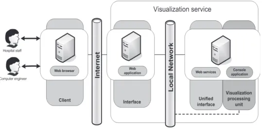
A system that enables visualization over the In-ternet is a component-based system. Identified components are client and visualization service. Visualization service is then granulated to in-terface, unified interface and visualization pro-cessing unit(Figure 1).
Client and visualization service are the main parts of the system presented here. Client’s
re-sponsibility is sending volume or other specific data, which must be accepted, processed and returned from visualization service.
Client or interface(for direct connection to stan-dards e. g. DICOM or HL7 CDA) should pro-vide a way to define processing routine for a given data to manage the visualization process. Client is responsible for the presentation of the visualized data. This can be provided by de-velopment of the new rendering software or in-tegrating software applications to render spe-cific responses from visualization service (3D viewer, graph generator, 3D printer).
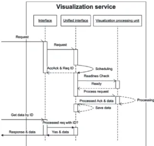
At first, client sends the data to the visualiza-tion service. Collaboravisualiza-tion of scientists from different areas is evident in process routine cre-ation on visualizcre-ation service. More users can be members of the visualization project( med-ical case). Processing routine can be changed without resending data to visualization service. Visualization services are responsible to process data according to the created processing routine upon the client’s request. Processed data is re-trieved on client, performing action of getting project by project’s temporal ID(Figure 2). To manage and process requests from client, visualization service has strict system architec-ture. This architecture consists of the interface, unified interface and visualization processing unit(Figure 1). Communication between inter-face and clients should be based on well used communication protocols and standards (such as HTTP, HL7 or DICOM). All requests should be mapped to unified interface of the visualiza-tion service.
Figure 2.Client sends data and processing routine to visualization service.
Figure 3.Client communicates with the interface according to selected protocol. Requests are unified and
sent to unified interface.
Interface is responsible for accepting the re-quests according to the implemented protocol
(Figure 3). Therefore, requests go through uni-fication process.
Unified request is forwarded to unified inter-face. Temporal ID is returned to the interface after acceptance of the unified request on the unified interface. Requests are scheduled on unified interface if visualization processing unit is down or another process is running (this is the case when only one visualization process-ing unit is connected to unified interface). The time between invocations of processing request is set by operating system scheduling function-ality. If visualization processing unit is ready, the process starts and generated data are re-turned to unified interface where it should be
saved. Client invokes get data by ID to see if specific request is processed through interface in event-based manner. Finally, generated data are returned if the request is processed.
3. Visualization of Medical Data over the Internet
The use of described VOI in the environment of exchange and visualization of medical data is called Visualization of Medical data over In-ternet(VMI). According to the defined key as-pects, security is the most considerable task on the level of implementation.
Sending medical data, such as data sets or other reports, must go through a process of anonymization. All personal data, that can iden-tify patient, must be moved before sending the data through the communication channel. Iden-tification should be managed in another way like temporal ID. Use of secured communica-tion channel is demanded even if anonymizacommunica-tion is used.
Security threats are almost present because of the provisional server settings without advanced knowledge of the security concept of the under-lying operating system.
Modern medical communication infra-structure consists of computer networks and other di-rect communication links. Generally, DICOM
[8] (Digital Imaging and COmmunications in Medicine) is widely used and accepted norm for storing medical data and transferring them through computer network. DICOM’s usage focused on radiology is overridden by new com-munication concepts, such as HL7(Health Level 7) [9]. HL7[3]can transfer all type of medical data through CDA (Clinical Document Archi-tecture) [4]. Future system should implement DICOM or HL7 interfaces to VMI system. In this paper, we have chosen and developed Web Portal called VMI for sending DICOM files through HTTP interface (web application) to unified interface.
profile). Web3D Consortium has formed spe-cial group to develop MedX3D standard for medical use as enhancement to the X3D[12].
4. Processing Routine and Project Definition
Modern visualization toolkits use processing routine defined as script in plain text file. This simple approach is good, but it cannot accom-modate the abstraction of the visualization pro-cess through the automatic imports of defined routines or special semantics according to the place of the visualization process subroutine definition. For example, generation of his-tograms must be implemented as the different functions with different parameters, but with our approach, the meaning of a histogram is defined by its place in the processing routine tree.
4.1. Project XSD Scheme
XML is the best standard to define processing routine. A strict scheme for XML processing routine defines allowed processing routine func-tionalities. It defines virtual object-oriented ap-proach. Some tags define creation of objects and the other tags define invocation of meth-ods with specific parameters. The scheme en-ables validation of lexical and semantic mean-ing of processmean-ing routine and demands strict im-plementation for vendors to implement defined functionalities.
Unification of all requests is verified by the Project XSD scheme. Project file should de-fine input file definition, input file data, secu-rity specific data, status and processing routine. Project files should be processed by visualiza-tion processing unit(Figure 1).
4.2. Web Service Interface
Web service implemented on unified interface should employ methods such as Request(input is XML data according Project XSD Scheme) and GetProject (Project ID). Exceptions are thrown if request is not valid according to Project XSD Scheme. If exception isn’t thrown, re-sponse parameter is project ID. Project ID iden-tifies visualized data. Invocation of GetPro-ject()method with returned ID will return visu-alized data.
Large datasets transferred through XML enlarge the size of initial dataset. Web services allow use of SOAP attachments to transfer binary data as they are without baseCode64 encoding. All binary files are attachments to SOAP message
[13].
5. Technical Overview of our VMI System
Client side of the system consists of web browser with plug-in to render X3D 3D objects and scenes generated by visualization service. Com-munication between client and visualization ser-vice is secured with SSL protocol.
Visualizations service is based on .Net platform developed by Microsoft. We have developed web application as interface to visualization ser-vice. Interface is available as web application through Microsoft’s web server IIS(Internet In-formation Services). Unified interface is im-plemented as web service with functionalities specified by concept of VOI, presented in Sec-tion 2. Also, project scheme follows definiSec-tion for transferred data.
Unified interface is defined in WSDL (Web Service Definition Language). Visualization processing unit is C#.NET console application triggered by windows task manager which pro-cesses requests stored in project repository( pro-ject repository is local or remote folder) man-aged by the unified interface. Processing vi-sualization unit saves results in project’s folder in the project repository. Client’s request for getting visualized data is forwarded through in-terface to unified inin-terface, according to defined VOI sequence diagram for visualization service.
5.1. VMI XSD Scheme and Implemented Functionalities
5.2. Visualization and Segmentation Framework
In the visualization processing unit, we have implemented segmentation framework. Seg-mentation framework can be used for surface rendering based on the original Marching cube algorithm[6]with one isolation value parameter
(Figure 4). We enhance segmentation frame-work to enable surface rendering based on the 2D area defined on 2D joint histogram. The idea is similar to the idea presented in [5] for volume rendering. Modification of marching cube is necessary to enable the same usage in surface rendering(Figure 5).
Processing routine could generate 1D histogram or 2D joint histogram(Figure 6; without area se-lection). Display of histogram is very important for correct segmentation and visualization. Se-lected area in 2D join histogram defines transfer function as shown in Figure 6. Isovalue is not defined by one threshold value, but combined values of intensity and derivative are used for segmentation in transfer function.
Segmentation framework presents segmented area of the same sized binary array. True presents vertex in a given area (according to 2D transfer function manifested as selection on 2D join histogram) and false for vertex out of selected area.
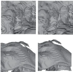
This approach generates hashed vertex data that presents segmented area and should be some-how interlaced to produce 3D objects. Binary selection produces artifacts on the result, so we develop separation method which filters seg-mented area with Gauss filter kernel in three dimensions. This interpolation of segmented data results in smoother models(Figure 7). It is a good example of adding a new functionality to visualization processing unit.
According to specific segmentation, some spe-cific operations are required such as area selec-tion. X3D shape writer creates X3D object as result of Isosurface rendering on segmented vol-ume data. Object writer creates obj file as sim-pler presentation without specific appearance definition.
Figure 4.Marching cube algorithm overview.
Figure 5.Segmentation framework and modified marching cube algorithm.
Figure 6.2D join histogram(2D Histogram)of volume data. X axis – intensity level, Y axis – magnitude of first
derivative, area presents occurrences N(x,y)in logarithmic scale. Selected area extracts sinuses and air.
6. Results
Logging to the VMI is required. The user can select one of previously created projects to check project status and get processed data. Also the user can create a new project(Figure 8). Creation of the new project goes through the wizard to collect project details like definition and selection of input file type and file which will be uploaded to web application. Input file
Figure 8.ASP.NET interface main screen with available projects(create new project option).
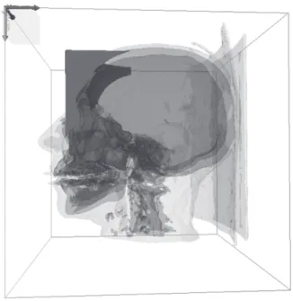
Figure 9.X3D scene generated from sample processing routine defined by VMI XSD Scheme. Sinuses & air, bones and soft tissue are presented. 1 825 394 polygons
in three high detailed X3D objects.
type can be “Raw data” or DICOM file. Raw data input file requires additional parameters. Project is then created and all data is saved on ASP.NET Application host server.
Finally, sample processing routine generates X3D scene consists of the X3D objects in 2 LOD levels. Sample generated X3D Scene pre-sented in higher level of details consists of the 1 825 394 polygons(Figure 9).
7. Conclusion
We have found that proposed architecture and given concepts of communication are accept-able according to key aspects we define. Strict definition of the communication based on pre-sented architecture and XSD Scheme process-ing routine definition should encourage research of the separated parts of the system to find out the most effective way of implementation and functionality enrichment. Our VMI can sim-ply adopt new interfaces such HL7 or direct DICOM connectors.
Medical technicians or biomedical engineers can be introduced as human support in sequence of visualization process. If we define this ap-proach as a new way of virtual medical environ-ment, the future research of presented architec-ture and communication concept of VOI is yet to be explored and developed.
References
[1] R. BHATTI, B. SHAFIG, M. SHEHAB, A. GHAFOOR,
Distributed Access Management in Multimedia IDCs. IEEE Computer, Vol. 38, No. 9 (2005), 60–69.
[2] F. EVESQUE, S. GERLACH, R. D. HERSCH, Building
3D anatomical scenes on the Web. Journal of Vi-sualization and Computer Animation, 13 (2002), 43–52.
[3] HL7 ORGANIZATION: HL7 Version 3,(2005),
http://www.hl7.org/.
[4] HL7 ORGANIZATION: The Clinical Document
Ar-chitecture,(2005),http://www.hl7.org/.
[5] J. KNISS, G. KINDLMANN, C. HANSEN,
[6] W. E. LORENSEN, H. E. CLINE, Marching Cubes: A High Resolution 3D Surface Construction Algo-rithm. Presented at theProceedings of SIGGRAPH ’87, Vol. 21, No. 4(1987), 163–169.
[7] B. MAROVIC, Z. JOVANOVIC, Visualization of 3D
fields and medical data and using VRML.Future Generation Computer Systems, 14 (1998), Issue 1–2, 33–49.
[8] NEMA: DICOMSTANDARD,(2004),
http://medical.nema.org/dicom/2004.html.
[9] H. OOSTERWIJK, The relationship between DICOM
and the CDA. Proceedings of 2nd International Conference on the Clinical Document Architecture,
(2004)Acapulco.
[10] A. POLIAKOV, E. ALBRIGHT, D. G. CORINA, R. F. OJEMANN, J. F. BRINKLEY, Server-based Approach to Web Visualization of Integrated 3-D Medi-cal Image Data. Presented at the Proceedings of AMIA2001,(2001).
[11] WEB3D CONSORTIUM: The X3D ISO standard,
(2005),http://www.web3d.org/.
[12] WEB3D CONSORTIUM: Medical real-time visual-ization and communication using X3D, (2005),
http://www.web3d.org/.
[13] WORLD WIDE WEB CONSORTIUM: SOAP 1.2
Attachment Feature,(2004),http://www.w3. org/TR/2004/NOTE-soap12-af-20040608/.
Received:June, 2007
Accepted:September, 2007
Contact addresses:
Bojan Blazona Ericsson Nikola Tesla Krapinska 45 10 000 Zagreb, Croatia e-mail:[email protected]
ˇ
Zeljka Mihajlovi´c University of Zagreb Faculty of Electrical Engineering and Computing Department of Electronics, Microelectronics, Computer and Intelligent Systems Unska 3 10 000 Zagreb, Croatia e-mail:[email protected]
ˇ
ZELJKAMIHAJLOVIC´ is an associate professor at the Department of Electronics, Microelectronics, Computer and Intelligent Systems, Uni-versity of Zagreb, Croatia. She received the B. S. degree in Electrical Engineering in 1988, the M. S. and Ph. D. degrees in computer science in 1993 and 1998 respectively, from the Faculty of Electrical Engineer-ing and ComputEngineer-ing, University of Zagreb. Her current research interests include visualization techniques, especially medical visualization, re-construction in volumetric space and surface rere-construction.