Americas Headquarters:
Cisco Application Networking for Microsoft
SharePoint Solutions Deployment Guide
Preface 3 Document Purpose 3 Prerequisites 3 Document Organization 4 Solution Overview 4 Solution Description 4 Process Flow 7 Solution Architecture 8
SharePoint Application Overview 8
Application and Application Networking Architecture 10 Enterprise Branch 11
WAN Simulation 11 Data Center 11 Server Farm 12
Packet Flow Without Cisco WAAS and Cisco ACE 14 Client Segment 15
WAN Segment 15 Server Segment 15 Response Times 15
Packet Flow with Cisco WAAS and Cisco ACE 16 Implementing and Configuring the Cisco ACE Solution 17
Implementation 17
Implementation Overview 17 What Was Implemented 17
What Was Not Implemented/Tested 17 Network Topology 18
Hardware or Components 18 Software 19
Features and Functionality 19
Features, Services, and Application Design Considerations 19 High Availability, Scalability, and Redundancy 19
Installing Cisco ACE and MSFC Configuration 20 Virtualization 21
Redundancy/High Availability 22 Remote Management Access 22
Configuring Interface(s) and Default Gateway 23 Probes 24
Real Server 26 Server Farm 27
Layer 4 Load Balancing 27 Layer 7 Load Balancing 28
Stickiness (Session Persistence) 29 SSL Termination 30
Configuration and Menus 32 Troubleshooting Configuration 32
Configuration Rollback 33 Results and Conclusions 33
Test Results —Server CPU Statistics 34
Implementing and Configuring the Cisco WAAS Solution 35 Implementation 35
Implementation Overview 35 What Was Implemented 35 What Was Not Implemented 36 Network Topology 36
Hardware or Components 37 Software 37
Features and Functionality 37
Features, Services, and Application Design Considerations 37 Scalability and Capacity Planning 38
High Availability 39
Device High Availability 39 N+1 Availability 39 Configuration Task Lists 39
Central Manager 39
Branch and Data Center Router 41 WAE-612-K9, WAE-7326-K9 42 Configuration and Menus 43 Troubleshooting Configuration 44
Cisco WAE Commands 44 Router Commands 44 Results and Conclusions 45 Network Management 51
Appendix A—Cisco ACE Configuration 52 Cisco ACE Admin Context 52 Cisco ACE SharePoint Context 53 Appendix B—Cisco WAE Configurations 56
Branch Cisco WAE Configuration 56 Data Center Cisco WAE Configuration 57
Appendix C—Cisco ACE Appliance Configuration and Test Results 60 Enterprise Branch 60 WAN Simulation 61 Data Center 61 ACE 4710 Configuration 62 Admin Context 62 SharePoint Context 63 Test Results 65 Site Navigation 65 File Upload 65 File Download 66 Appendix D—References 67
Cisco Advanced Services 68
Cisco Services Help Accelerate and Optimize ANS Deployments 68
Preface
Document Purpose
To address challenges associated with today’s mission critical enterprise application deployments, Cisco, in collaboration with Microsoft, offers Cisco Application Networking Solution for Microsoft SharePoint Solutions, an enterprise network architecture for deploying Microsoft Office SharePoint Server (MOSS) 2007 with Cisco networking equipment (Joint Solution) with best practices and implementation guidance that optimizes application availability, performance, and security and lowers application ownership costs.
Featuring the Cisco Application Control Engine (ACE) and Wide Area Application Services (WAAS) product families, collectively known as Cisco Application Networking Services (ANS), that provide data center, branch, and remote end user application optimization services, the Joint Solution addresses the following challenges:
• Recovery time and point objectives for business continuity
• Application response time over limited Wide Area Network (WAN) connections
• Application, server, network, and service oriented architecture (SOA) security
• Reduced capital and operational costs for applications, servers, and networking
Cisco and Microsoft cooperated in all phases of the Cisco Application Networking for Microsoft SharePoint Solutions testing, including lab set-up at Cisco and Microsoft offices, solution functional and performance testing, and this deployment guide. Cisco and Microsoft jointly validate that the lab setup and Joint Solution testing represents best efforts in creating a realistic customer deployment and accurate documentation of such deployment.
The purpose of this document is to describe the Joint Solution enterprise network architecture along with deployment best practices and guidance.
Prerequisites
• Working knowledge of the MOSS application
• Experience with basic networking and troubleshooting
• Experience installing the Cisco products covered by this network design, including the Cisco ACE and WAAS product families
• Working knowledge of Cisco’s Internetworking Operating System (IOS)
Document Organization
The following table provides a brief description of each section.
Solution Overview
Solution Description
The Joint Solution offers optimized MOSS 2007 application availability, performance, security, and costs by providing application optimization services as follows:
• Application availability
Cisco ACE product family application optimization services for MOSS 2007 high availability: – Server and application health monitoring—Continuously and intelligently monitors application
and database availability.
– Server load balancing—Efficiently routes end user and Web services requests to the best available server.
– Network platform health monitoring—Ensures continuity of business operations through mirroring end user transaction states across pairs of network devices.
• Application performance
Cisco ACE and WAAS product family application optimization services for MOSS 2007 high performance:
Section Description
Solution Overview A high-level introduction to the solution.
Introduces the solution, historical aspects, potential benefits, and scope and limitations. Solution Architecture Describes the architecture of the Joint Solution. Implementing and Configuring the Cisco ACE
Solution
Describes configuration and implementation of Cisco ACE within the Joint Solution.
Implementing and Configuring the Cisco WAAS Solution
Describes configuration and implementation of WAAS within the Joint Solution.
Network Management Describes the network management software used
– WAN optimization—Provides intelligent caching, compression, and protocol optimization that yields up to 34 times faster downloads, 50 percent faster site navigation, and 88 percent less bandwidth (see Results and Conclusions).
– Server offloading—Specialized hardware that offers greater processing efficiency for application optimization services such as server load balancing, Secure Socket Layer termination, and traffic compression, which frees up to 71 percent of application server processing and memory to focus on business logic computations.
– Server load balancing—Substitutes for Microsoft Network Load Balancing (NLB) load balancing.
– Secure Socket Layer (SSL) termination—Terminates 15,000 connections per second.
– Transmission Control Protocol (TCP) connection management—Reduces the numberof TCP connections to server.
– Server health monitoring—Substitutes for SharePoint native server health monitoring. – Traffic compression—Scalable LZ compression functionality.
– Object caching—Reduce requests to server.
• Application security
Cisco ACE product family application optimization services for MOSS application and data security:
– SSL termination—Efficiently encrypts and decrypts SSL enabled traffic, which facilitates the use of intrusion detection and prevention solutions before traffic reaches the servers.
– End user access control—Provides Access Control Lists (ACLs) to protect client-to-server traffic from worms and intruders that attack vulnerable open server ports not used by the application.
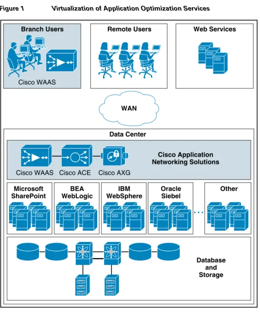
• Virtualization of application optimization services
Virtualization of application optimization services supplies such services for multiple SharePoint instances as well as other enterprise applications (see Figure 1). Specifically, a single physical Cisco ACE can be virtualized into multiple logical Cisco ACEs in which application traffic can traverse between virtualized Cisco ACEs. This virtualization of load balancing is an exclusive Cisco feature.
Figure 1 Virtualization of Application Optimization Services
The application optimization services of the Joint Solution reside in both the data center and the branch to offer end-to-end value, from branch and remote users, all the way through to the database and information storage.
• Data center application optimization services
Cisco ACE and WAAS reside in the data center and are arranged to provide virtualized application optimization services for multiple MOSS 2007 instances as well as other enterprise applications. Because of their unique location, these solutions can take intelligent action on end-user traffic before it is routed to the MOSS 2007 application servers, including server load balancing, server health monitoring, SSL decryption, TCP connection consolidation, and end user access control. While some of these functions could be provided natively by Microsoft or third party server-based solutions, Cisco networking provides these services cost-effectively, freeing up server processing and memory needs to focus on business logic computation.
• Wide area application optimization services Branch Users
Microsoft SharePoint
Cisco WAAS
Cisco WAAS Cisco ACE Cisco AXG
WAN Cisco Application Networking Solutions Database and Storage Other BEA WebLogic IBM WebSphere Oracle Siebel Remote Users Data Center Web Services 222917
Cisco WAAS also resides in the branch office and is arranged to provide virtualized application optimization services for all application users in that location. Together with the data center WAAS deployment, the two offer a WAN optimization service through the use of intelligent caching, compression, and protocol optimization.
When the MOSS 2007 application servers respond to end-user requests, Cisco WAAS compresses the response and then most efficiently passes it across the WAN with minimal bandwidth usage and maximum speed. Commonly used information is cached both at the WAAS solution in the branch as well as in the Cisco ACE solution in the data center, which significantly reduces the burden on the servers and the WAN.
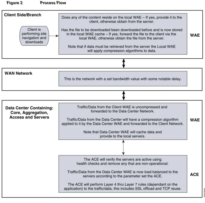
Process Flow
Note The Cisco Wide Area Application Services (WAAS) software runs on the Cisco Wide-Area Application Engine (WAE).
Figure 2 Process Flow
Solution Architecture
SharePoint Application Overview
MOSS 2007 is a portal-based collaboration and document management platform. It can be used to host web sites, termed SharePoint Portals, which can be used to access shared workspaces and documents, as well as specialized applications, such as wikis and blogs, from within a browser.
MOSS 2007 functionality is exposed as Web parts, which are components that implement certain functionality, such as a task list or discussion pane. These Web parts are then composed into Web pages, which are then hosted in the SharePoint Portal. SharePoint sites are actually ASP.NET applications, which are served using Microsoft Internet Information Server (IIS) and use a Microsoft SQL Server database as data storage backend.
Client is performing site navigation and downloads
Does any of the content reside on the local WAE – If yes, provide it to the client, otherwise obtain from the server.
Has the file to be downloaded been downloaded before and is now stored in the local WAE cache – If yes, forward the file to the client via the
local WAE, otherwise obtain the file from the server. Note that if data must be retrieved from the server the Local WAE
will apply compression algorithms to data.
This is the network with a set bandwidth value with some notable delay.
Traffic/Data from the Client WAE is uncompressed and forwarded to the Data Center Network.
Traffic/Data from the Data Center will have a compression algorithm applied to it by the Data Center WAE and forwarded to the Client Network.
Note that Data Center WAE will cache data and provide to the local servers.
The ACE will verify the servers are active using health checks and remove any that are non-operational. Traffic/Data from the Data Center WAE is now load balanced to the
servers according to the parameter set the ACE. The ACE will perform Layer 4 thru Layer 7 rules (dependant on the application) to the traffic/data, this includes SSL offload and TCP reuse. Data Center Containing:
Core, Aggregation, Access and Servers WAN Network Client Side/Branch WAE WAE ACE 222792
The SharePoint family of products is composed of three different applications. Windows SharePoint Services (WSS) is a free add-on to Windows Server. WSS offers the basic portal infrastructure and collaborative editing of documents, as well as document organization and version control capabilities. It also includes end user functionality such as workflows, to-do lists, alerts, and discussion boards, which are exposed as web parts to be embedded into SharePoint Portal pages. WSS was previously known as SharePoint Team Services.
Microsoft Office SharePoint Server (MOSS) is a paid component of Microsoft Office suite. MOSS integrates with WSS and adds more functionality to it, including better document management, indexed search functionality, navigation features, RSS support, wikis, and blogs, as well as features from Microsoft Content Management Server. It also includes features for business data analysis as well as integration with Microsoft Office applications, such as project management capabilities or exposing Microsoft Office InfoPath forms via a browser. It can also host specific libraries, such as PowerPoint Template Libraries provided the server components of the specific application are installed. MOSS was previously known as SharePoint Server and SharePoint Portal Server.
MOSS 2007 is composed of a three-tier architecture as described below. The first tier is a Web browser for a client. The middle tier consists of a Web and application server running the WSS application with MOSS plugging-in functionality where required, generally a search service which crawls the data store creating an index, and a number of other services. The third tier is the database server.
The middle tier can be scaled out by load balancing more web and application servers in the middle tier and building larger clusters of SQL Server in the third tier.
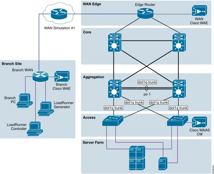
Application and Application Networking Architecture
Figure 3 Application and Application Networking Architecture
The Joint Solution uses WAAS to enhance performance and Cisco ACE to reduce the load on resources in the server farm. The WAAS and Cisco ACE each provide a unique benefit to the solution, however there are additional benefits when they are used together as the two solutions are complimentary. The Cisco ACE provides load balancing to the server farm. If the application uses SSL, then the Cisco ACE can provide SSL termination offload, thereby increasing efficiency by removing the load on the servers’ resources and allowing the servers to process more transactions. Increased server efficiency also results if the Cisco ACE is used to provide TCP reuse.
The Joint Solution architecture is based on the Enterprise Branch Wide Area Application Services Design Guide architecture is based on the Enterprise Branch Wide Area Application Services Design Guide (Enterprise Branch Design) and the Data Center Infrastructure Design Guide 2.1, both found at www.cisco.com/go/srnd.
In the Joint Solution architecture, the WAAS Solution is installed within the Cisco Wide Area Application Engine (WAE) Appliances.
Server Farm WAN Simulation #1 Branch PC Access Aggregation WAN Edge Core Branch Site 222810 Edge Router Branch WAN WAN Cisco WAE LoadRunner Generator LoadRunner Controller Branch Cisco WAE Cisco WAAS CM dot1q trunk po 1 dot1q trunk
dot1q trunk dot1q trunk
Enterprise Branch
The Enterprise Branch Design shows the Cisco WAE appliance connected to the local branch router, typically a Cisco Integrated Services Router (ISR). The design provides scalability and availability as compared to installing a Cisco WAAS Network Module within a Cisco ISR as the Cisco ISR must share its resources.
HP Mercury LoadRunner, running on a personal computer in the branch, simulates users that would perform certain tasks in the application.
The traffic is redirected to the Cisco WAE via Web cache communications protocol (WCCP) from the branch router. The Cisco WAE performs the following functions:
• Locally cached—If the data that is being requested is locally cached, the Cisco WAE responds to the requestor with the cached data and requests only required data from the server farm. This allows the WAN to become more efficient as only “needed data” requested.
• New data—If the data that is being forwarded to the server farm or coming from the server farm, the Cisco WAE performs compression algorithms on the data allowing for the WAN to become more efficient.
WAN Simulation
The WAN simulator provides simulations of the following WAN links:
1. WAN Type 1 (Intracontinental or T1)
a. Bandwidth - 1.544 Mbps, ESF, B8ZS, Delay - 100 mS, Loss - drop one packet in every 1000 packets (0.1%)
2. WAN Type 2 (Intercontinental)
a. Bandwidth - 512 Kbps, ESF, B8ZS, Delay - 200 mS, Loss - drop one packet in every 500 packets (0.2%)
Data Center
The data center (DC) follows the design guidelines found in the Data Center Infrastructure Design Guide 2.1, a Cisco Validated Design found at http://www.cisco.com/go/srnd. The design consists of a data center WAN router, core, aggregation, and access Ethernet switching, and the server farm where the application resides. In this document, the focus is on the DC WAN router, aggregation, and the server farm. The core Ethernet switching provides routing to and from the DC WAN router and the aggregation. The access Ethernet switching provides Layer 2 connectivity for the server farms to the aggregation. The DC WAN router performs the same function as the branch WAN router by redirecting traffic to the DC Cisco WAE. The DC Cisco WAE performs the following:
• Locally cached—If the data that is being requested is locally cached, the Cisco WAE responds to the requestor with the cached data and requests only required data from the branch. This allows the WAN to become more efficient as only “needed data” is requested.
• New data—If the data that is being forwarded to the branch or coming from the branch, the Cisco WAE performs compression algorithms on the data allowing for the WAN to become more efficient. Included in the data center is the Cisco WAAS central manager (CM), which runs on the Cisco WAE Appliance. The Cisco WAAS CM provides a centralized mechanism for configuring Cisco WAAS features and reporting and monitoring Cisco WAAS traffic. It can manage a topology containing
thousands of Cisco WAE nodes and be accessed from any Web browser using SSL. The Cisco WAAS CM can be configured for high availability by deploying a pair of Cisco WAE appliances as central managers.
Within a Cisco WAAS topology, each Cisco WAE runs a process called central management system (CMS). The CMS process provides SSL-encrypted bidirectional configuration synchronization of the Cisco WAAS CM and the Cisco WAE appliances. The CMS process is also used to exchange reporting information and statistics at a configurable interval. When the administrator applies configuration or policy changes to a Cisco WAE appliance or a group of Cisco WAE appliances, the Cisco WAAS Central Manager automatically propagates the changes to each of the managed Cisco WAEs. Cisco WAEs that are not available to receive the changes will receive them the next time the appliances become available. The aggregation segment contains Cisco ACE, which provides the following features:
• Virtualization—Virtualization is device partitioning into multiple contexts, where each context can be configured for different applications and is independent of any others. In the Joint Solution, Cisco ACE is configured with the Admin context and the SharePoint context. Note that the Cisco ACE can support up to 250 contexts.
• Session persistence—Session persistence is the ability to forward client requests to the same server for the duration of the session. MOSS requires either source Internet Protocol (IP) based session persistence or Hypertext Transfer Protocol (HTTP) cookie based session persistence.
• Transparent interception—Transparent interception performs a Network Address Translation (NAT) function to conceal the real server IP address that is residing in the server farm. The SharePoint context is configured with a Virtual IP (VIP) that provides a single address that users use to connect to the server farm. This allows users to access the MOSS application by placing a single IP in the Web browser.
• Allowed server connections—Allowed server connections is the maximum number of active connections value on a per-server basis and/or globally to the server farm.
• Health monitoring—Health monitoring is used to track the state of the server and determine its ability to process connections in the server farm. The SharePoint context used a compound probe to determine if servers are operational and responding to HTTP requests.
Cisco ACE provides load balancing of the traffic to the server farm using one of the following methods: Round Robin, Weighted Round Robin, Least Connections, Hash address, Hash cookie, Hash Header, and Hash URL. In the Joint Solution, Least Connections was used, which selects the server with the fewest number of server connections. Cisco ACE is also used to provide SSL offload and TCP reuse.
Inter-chassis Cisco ACE redundancy was used, in which a Cisco ACE module in one Cisco Catalyst 6500 Series Switch chassis is protected by a Cisco ACE module in a peer Cisco Catalyst 6500 Series Switch chassis connected by a fault tolerant (FT) VLAN. The FT VLAN is used to transmit flow-state information, configuration synchronization information, and the redundancy heartbeat.
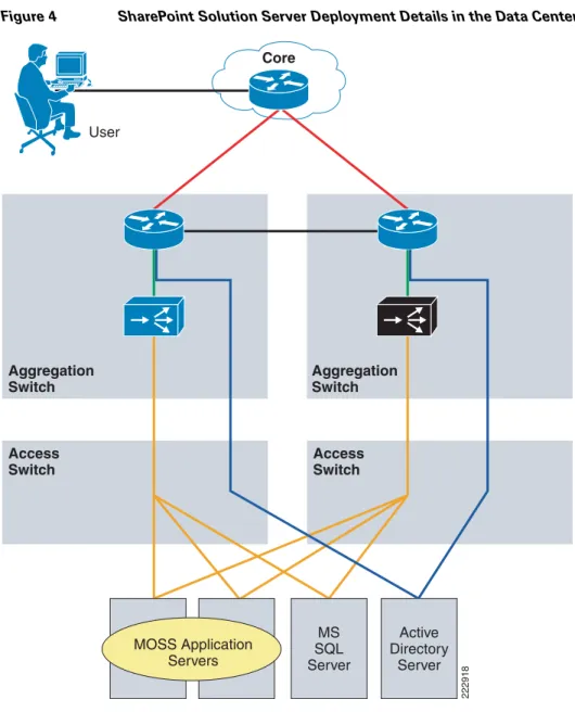
Server Farm
The server farm consists of four physical servers—two application servers, one database server, and one active directory server
Two physical application servers, load balanced by Cisco ACE, each have the following hardware and software configuration:
• Microsoft Office SharePoint Server (MOSS) 2007
• Microsoft Windows Server 2003 Enterprise Edition Service Pack 1 including Windows SharePoint Server (WSS) and Internet Information Services
• 1 GB RAM
• Two mirrored 36.4 GB serial ATA hard drives
The database server, which is connected to both application servers, has the following hardware and software configuration:
• Microsoft SQL Server 2005
• Microsoft Windows Server 2003 Enterprise Edition Service Pack 1
• Two dual core Intel Xeon process - 3.4 GHz
• 3.5 GB RAM
• Two mirrored 72.8 GB serial ATA hard drives
The active directory server has the following hardware and software configuration:
• Microsoft Windows Server 2003 Enterprise Edition Service Pack 1
• Two dual core Intel Pentium 3 - 697MHz GHz
• 256 MB RAM
• 14 GB SATA hard drive
The database and active directory servers are not load balanced. No virtualization was used on any of the servers.
Figure 4 SharePoint Solution Server Deployment Details in the Data Center
Packet Flow Without Cisco WAAS and Cisco ACE
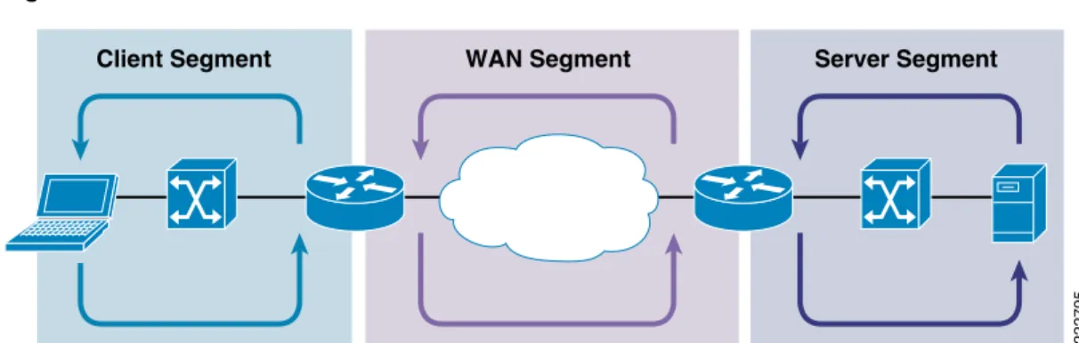
Application packet flow from a remote site can be categorized into three segments, client, WAN, and server. User 222918 Core Access Switch Aggregation Switch Aggregation Switch Access Switch Active Directory Server MS SQL Server MOSS Application Servers
Figure 5 Normal Packet Flow
Client Segment
The client segment is defined as the location into which users are connected that allows them to obtain or retrieve data from the application residing on the server farm. Users have connected personal computers (PC) to a local external switch or an integrated switch/router. When a user opens a browser and provides a URL that points to the application residing on the server, the data is sent from the PC to the switch. The switch forwards the data to the router that connects to the wide area network (WAN).
WAN Segment
The WAN provides the connectivity from the client location to the data center where the server farm is located. The WAN is provided by a service provider (SP) with a given service level agreement (SLA). The WAN inherently introduces delay and packet loss to the data traffic (packets).
Server Segment
The server segment consists of a highly available and resilient core, aggregation, and access Ethernet switching. The core routes the data traffic to and from the WAN and the aggregation layer. The aggregation layer provides consolidation of multiple access layers and routes the access layer traffic into the core. The aggregation layer also takes the data traffic from the core layer and sends it to the appropriate access layer. The access layer provides connectivity to the server farm where the
applications reside. The data traffic (URL, per the example) from the client segment transverses the data center until the data traffic is received by the appropriate server. The server’s application responds to the request and responds back to the user by forwarding the appropriate data back the client segment.
Response Times
Transaction response time consists of server response time and WAN round trip time. Delays in the WAN or the time to process a request on a server lead to a longer wait times for data to be viewed by the end user.
WAN Segment Server Segment
Client Segment
Packet Flow with Cisco WAAS and Cisco ACE
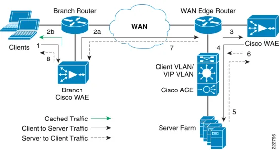
Figure 6 Packet Flow with Cisco WAAS and Cisco ACE
The following sequence describes the handshake between a client and the server farm and the data transfer phase:
1. The client sends a TCP SYN (synchronize) packet to the server farm VIP address. The packet is forwarded to the branch router. The branch router intercepts the packet with WCCP and forwards it to the branch Cisco WAE appliance.
2. a.) The branch Cisco WAE applies a new TCP option (0x21) to the packet if the application is identified for optimization by an application classifier. The branch Cisco WAE adds its device ID and application policy support to the new TCP option field. This option is examined and understood by other Cisco WAEs in the path as the ID and policy fields of the initial Cisco WAE device. The initial ID and policy fields are not altered by another Cisco WAE. The packet is forwarded to the branch router and then to the WAN. b.) During the data transfer phase, if the requested data are in its cache, the branch Cisco WAE returns its cached data to the client. Traffic does not travel through the WAN to the server farm. Hence both response time and WAN link utilization are improved.
3. The packet arrives on the WAN edge router. The WAN edge router intercepts the packet with WCCP and forwards the packet to the data center Cisco WAE.
4. The data center Cisco WAE inspects the packet. Finding that the first device ID and policy is populated, it updates the last device ID field (first device ID and policy parameters are unchanged). The data center Cisco WAE forwards the packet to the WAN edge router. The edge router forwards it to the Cisco ACE. The Cisco ACE forwards the packet to the server farm VLAN with TCP option 21 removed. TCP options are usually ignored by the server, even if it is still in place. The Cisco ACE performs load balancing to the data traffic. Other functions the Cisco ACE performs include SSL offload, TCP reuse, cookie and IP sticky pertinence.
Data Center Branch Office 2b 1 8 2a 7 4 3 Cisco WAE Branch Router Server Farm Client VLAN/ VIP VLAN Cisco ACE Cached Traffic
WAN Edge Router
222796
WAN
Branch Cisco WAE
Client to Server Traffic Server to Client Traffic
6
5 Clients
5. The following steps are for reverse traffic flow. The server farm sends the SYN/ACK packet back to the client with no TCP option. The packet from the server farm VLAN is matched and forwarded to the Cisco ACE and then to the WAN edge router. The WAN edge router forwards the packet to the data center Cisco WAE. The data center Cisco WAE marks the packet with TCP option 0x21. During the data transfer phase, the data center Cisco WAE caches the data if the data are not in its cache.
6. The data center Cisco WAE sends the packet to the WAN edge router.
7. The packet travels through the WAN and arrives at the branch router. The branch router intercepts the packet and forwards it to the branch Cisco WAE. The branch Cisco WAE is aware of the Cisco WAE in the data center because the SYN/ACK TCP option 0x21 contains an ID and application policy. The auto-negotiation of the policy occurs as the branch Cisco WAE compares its
application-specific policy to that of its remote peer defined in the TCP option. At this point, the data center Cisco WAE and branch Cisco WAE have determined the application optimizations to apply on this specific TCP flow. During the data transfer phase, the branch Cisco WAE caches the data if the data are not in its cache.
8. The packet is forwarded to the branch router and then to the client.
Implementing and Configuring the Cisco ACE Solution
Implementation
Implementation Overview
The Cisco ACE module used in this solution is deployed in a Cisco Catalyst 6509 switch in the data center aggregation layer. The Cisco ACE module is deployed in routed mode where the client and server side VLANs each support unique IP subnets. In this deployment mode the Cisco ACE acts as the default gateway for the application servers.
What Was Implemented
Key features implemented on the Cisco ACE module to support this application are:
• Layer 4 load balancing
• Persistence based on source IP address
• Layer 7 load balancing for SSL termination and TCP reuse
• Server health monitoring
• Connection replication for stateful failover
What Was Not Implemented/Tested
The following was not implemented in this solution:
Network Topology
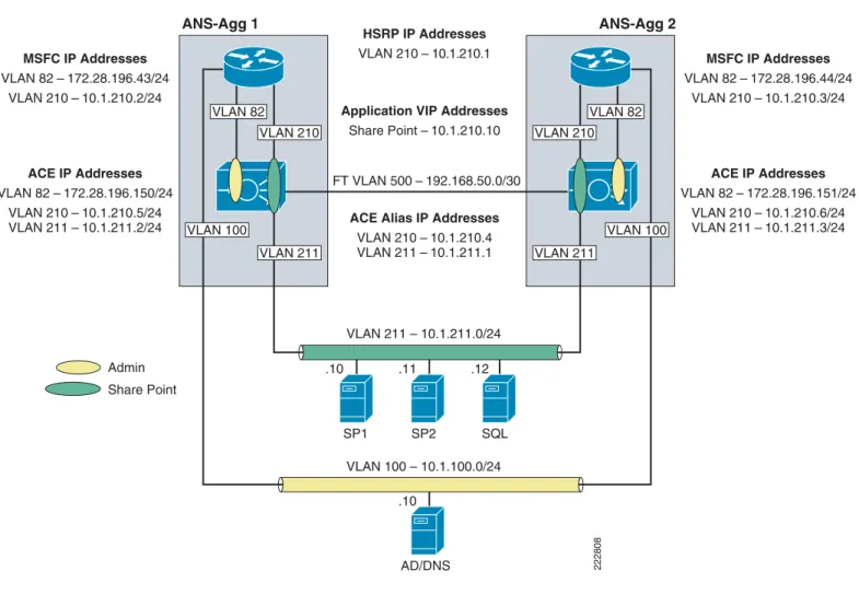
Figure 7 Network Topology
Hardware or Components
Note For the data center infrastructure, refer to the Data Center Design and Implementation Guide at http://www.cisco.com/go/srnd.
Table 1 Hardware
Product Chassis Modules Interfaces Memory
ACE20-MOD-K9 Must be inserted into a Cisco Catalyst 65XX chassis
N/A Console port 957928
kB AD/DNS VLAN 100 – 10.1.100.0/24 SP1 .10 .11 .10 .12 SP2 SQL HSRP IP Addresses VLAN 210 – 10.1.210.1
ACE Alias IP Addresses VLAN 210 – 10.1.210.4 VLAN 211 – 10.1.211.1 ACE IP Addresses VLAN 82 – 172.28.196.150/24 VLAN 210 – 10.1.210.5/24 VLAN 211 – 10.1.211.2/24 MSFC IP Addresses VLAN 82 – 172.28.196.43/24 VLAN 210 – 10.1.210.2/24 ACE IP Addresses VLAN 82 – 172.28.196.151/24 VLAN 210 – 10.1.210.6/24 VLAN 211 – 10.1.211.3/24 MSFC IP Addresses VLAN 82 – 172.28.196.44/24 VLAN 210 – 10.1.210.3/24 Application VIP Addresses
Share Point – 10.1.210.10 FT VLAN 500 – 192.168.50.0/30 VLAN 211 – 10.1.211.0/24 Admin Share Point VLAN 82 VLAN 100 VLAN 211 VLAN 210 VLAN 82 VLAN 100 VLAN 211 VLAN 210 222808 ANS-Agg 1 ANS-Agg 2
Software
Features and Functionality
Features, Services, and Application Design Considerations
Cisco ACE module support three primary types of session persistence, source IP based, HTTP cookie inserted by the application server, and HTTP cookie inserted by the Cisco ACE module. MOSS can work with each of these types of session persistence. Considerations used to determine which is best are based on deployment environment. If MOSS is deployed in an intranet environment, then simple source IP based sticky is probably adequate. If MOSS is deployed facing the Internet then a the problem of users coming through mega-proxy servers becomes an issue and it is probably better to use HTTP based cookie session persistence. The cookie contains information that the Cisco ACE uses to ensure persistence to a specific real server. Refer to Configuration Task Lists and Appendix A—Cisco ACE Configuration for configuration information.
High Availability, Scalability, and Redundancy
The Cisco ACE also offers multi-tiered redundancy, availability, and scalability for maximum protection. It is the only product in the industry that offers three types of high availability:
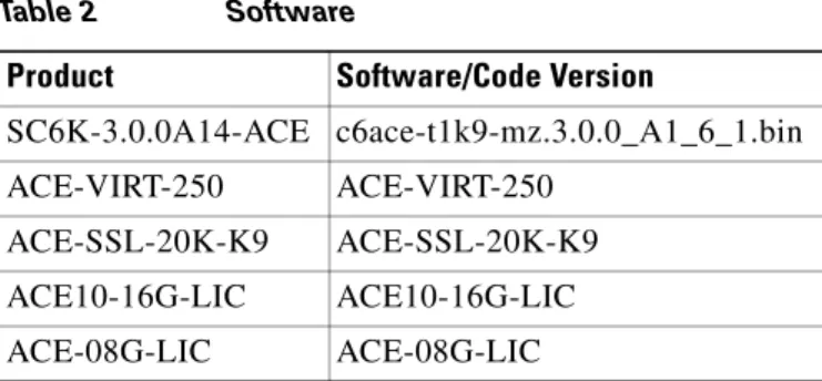
Table 2 Software
Product Software/Code Version
SC6K-3.0.0A14-ACE c6ace-t1k9-mz.3.0.0_A1_6_1.bin
ACE-VIRT-250 ACE-VIRT-250
ACE-SSL-20K-K9 ACE-SSL-20K-K9
ACE10-16G-LIC ACE10-16G-LIC
ACE-08G-LIC ACE-08G-LIC
Table 3 Features and Functionality
Product Features and Functionality Used in the Solution
ACE20-MOD-K9 • Virtualization
• Load balancing
• Session persistence
• Server health monitoring
• SSL offload (up to 15,000 SSL sessions via licensing)
• TCP reuse
• Transparent interception support for redundant configurations (intra-chassis, inter-chassis, inter-context)
• Inter-chassis—A Cisco ACE in one Cisco Catalyst 6500 is protected by a Cisco ACE in a peer Cisco Catalyst 6500.
• Intra-chassis—A Cisco ACE in a Cisco Catalyst 6500 is protected by another Cisco ACE in the same Cisco Catalyst 6500 (the Cisco Catalyst 6500 has solid redundancy built in).
• Inter-partition—Cisco ACE supports high availability between virtual partitions configured across two modules to allow specific partitions to fail over without affecting the other partitions and applications on a given module.
All these application availability modes provide rapid, stateful application redundancy with replication of connection state and sticky tables.
Inter-chassis and inter-partition redundancy is used in the Joint Solution. Refer to Configuration Task Lists and Appendix A—Cisco ACE Configuration for configuration information.
Configuration Task Lists
This section describes the steps necessary to configure the equipment.
Installing Cisco ACE and MSFC Configuration
A Cisco ACE module interacts with clients and servers via VLANs that are set up in the Cisco Catalyst 6500 Series/Cisco 7600 Series Supervisor Engine 720 (Sup720). These VLANs must be configured on the Sup720 to be allowed to be sent to the Cisco ACE module. Without this configuration, by default Cisco ACE does not receive traffic from any VLAN.
The following sample configuration steps are performed on the MSFC. Refer to Appendix A—Cisco ACE Configuration for a complete configuration.
Step 1 Add Cisco ACE VLANs and database server VLAN. For example: vlan 210 name ACE-CLIENT ! vlan 211 name ACE-SERVER ! vlan 500 name ACE-FT-VLAN !
Step 2 Add the SVCLC configuration.
For this deployment, Cisco ACE is installed in slot 3 in the Cisco Catalyst 6500 chassis. The following configuration needs to be added to allow Cisco ACE-specific VLAN traffic to be directed towards Cisco ACE:
svclc multiple-vlan-interfaces svclc module 3 vlan-group 1 svclc vlan-group 1 210,211,500
Step 3 Add the Switch Virtual Interface (SVI) configuration.
The SVI (interface VLAN) configuration defines Layer 3 instance on the router MSFC. The Cisco ACE client side VLAN SVI configuration is:
interface Vlan210
description ACE Client Side VLAN ip address 10.1.210.2 255.255.255.0
standby 210 ip 10.1.210.1 standby 210 Priority 120
Virtualization
Virtualization is a method to allocate available Cisco ACE resources into two or more contexts for security and management purposes. Up to 250 (5 with no additional license requirements) contexts can be configured on Cisco ACE. Resources can be allocated to each context to avoid a single context consuming the entire pool of resources. This document only covers key virtualization configuration. Within each context, Domains and Role Base Access Controls (RBACs) can be further configured to provide additional security and access control to the resources.
Context Configuration
Sample context configuration steps are:
Step 1 Configure resource-class(es):
ACE_1/Admin(config)# resource-class Gold
<cr> Carriage return.
The different resources that can be segmented are: ACE_1/Admin(config-resource)# limit-resource ? acl-memory Limit ACL memory
all Limit all resource parameters buffer Set resource-limit for buffers
conc-connections Limit concurrent connections (thru-the-box traffic) mgmt-connections Limit management connections (to-the-box traffic) proxy-connections Limit proxy connections
rate Set resource-limit as a rate (number per second) regexp Limit amount of regular expression memory
sticky Limit number of sticky entries xlates Limit number of Xlate entries
Step 2 Configure context(s):
A context is configured by giving it a name, allocating VLANs, and assigning it to a resource-class (previous step):
context SharePoint
description SharePoint Testing allocate-interface vlan 210-211 member Gold
Step 3 To configure per-context features and functionality, simply change to the context created in step 2. At that point, you have accessed a virtually new Cisco ACE context.
Redundancy/High Availability
To provide high availability and redundancy, Cisco ACE can be set up and configured in a redundant mode. Cisco ACE can be configured in a typical active/backup redundancy mode or active/active (per context) redundancy mode.
! Configure FT interface ! ft interface vlan 500 ip address 10.1.500.1 255.255.255.248 peer ip address 10.1.500.2 255.255.255.248 no shutdown ! ! Configure FT peer ! ft peer 1 ft-interface vlan 500 heartbeat count 3 heartbeat interval 1000 !
! Configure interface tracking !
ft track interface VLAN210 priority 200
!
! Create a fault tolerant group ! ft group 1 peer 1 priority 200 preempt associate-context admin inservice !
By assigning context(s) to a FT group, a network administrator can create multiple groups for multiple contexts where the ACTIVE contexts can be distributed among the two Cisco ACE modules. This setup provides active/active redundancy setup for load sharing and high availability.
Remote Management Access
To access the Cisco ACE module remotely using Telnet, SSH, SNMP, HTTP, or HTTPS or to allow ICMP access to the Cisco ACE module, a policy must be defined and applied to the interface(s) the access is entering.
The configuration steps in this section are required for both the Admin context and the application context. The following example is for the application context. Refer to Appendix A—Cisco ACE Configuration for a complete configuration.
Step 1 Configure class-map of type management:
class-map type management match-any REMOTE-MGMT 10 match protocol ssh any
20 match protocol telnet any 30 match protocol icmp any 40 match protocol http any 50 match protocol https any
policy-map type management first-match REMOTE-ACCESS class REMOTE-MGMT
permit
Step 3 Apply policy-map to the VLAN interfaces: interface vlan 210
service-policy input REMOTE-ACCESS
interface vlan 211
service-policy input REMOTE-ACCESS
Configuring Interface(s) and Default Gateway
Interface VLANs need to be configured for Layer 3 connectivity to Cisco ACE. Service policies for load balancing, security, and management access to Cisco ACE are also applied at the interface VLAN level. The configuration steps in this section are required for both the Admin context and the application context. The following example is for the application context. Refer to Appendix A—Cisco ACE Configuration for a complete configuration.
Step 1 Define an access-list to permit/deny traffic through Cisco ACE. For example: access-list ANYONE line 10 extended permit icmp any any
access-list ANYONE line 20 extended permit ip any any
Step 2 Configure IP address and network mask of the interface(s): interface vlan 220 ip address 10.1.210.5 255.255.255.0 peer ip address 10.1.210.6 255.255.255.0 alias 10.1.210.4 255.255.255.0 interface vlan 211 ip address 10.1.211.2 255.255.255.0 peer ip address 10.1.211.3 255.255.255.0 alias 10.1.211.1 255.255.255.0
Step 3 Apply management access policy and access-group to the interface(s), no shut of the interface(s): interface vlan 210
access-group input ANYONE access-group output ANYONE
service-policy input REMOTE-ACCESS no shutdown
interface vlan 211
access-group input ANYONE access-group output ANYONE
service-policy input REMOTE-ACCESS no shutdown
Step 4 Default gateway can be configured as: ip route 0.0.0.0 0.0.0.0 10.1.210.1
Step 5 Verify interfaces are recognized by MSFC and operational.
Type show interface and verify the VLANs are up and assigned from the supervisor. Here is an example of a working output:
vlan210 is up
Hardware type is VLAN
MAC address is 00:1b:d5:9b:88:ed
Virtual MAC address is 00:0b:fc:fe:1b:02 Mode : routed
IP address is 10.1.210.5 netmask is 255.255.255.0 FT status is active
Description:Client side vlan MTU: 1500 bytes
Last cleared: never
Alias IP address is 10.1.210.4 netmask is 255.255.255.0
Peer IP address is 10.1.210.6 Peer IP netmask is 255.255.255.0 Assigned from the Supervisor, up on Supervisor
53808467 unicast packets input, 17900167965 bytes 7331701 multicast, 7776 broadcast
0 input errors, 0 unknown, 0 ignored, 0 unicast RPF drops 91028995 unicast packets output, 5455629020 bytes
4 multicast, 5202 broadcast 0 output errors, 0 ignored
vlan211 is up
Hardware type is VLAN
MAC address is 00:1b:d5:9b:88:ed
Virtual MAC address is 00:0b:fc:fe:1b:02 Mode : routed
IP address is 10.1.211.2 netmask is 255.255.255.0 FT status is active
Description:Server side vlan MTU: 1500 bytes
Last cleared: never
Alias IP address is 10.1.211.1 netmask is 255.255.255.0
Peer IP address is 10.1.211.3 Peer IP netmask is 255.255.255.0 Assigned from the Supervisor, up on Supervisor
83222640 unicast packets input, 95861661879 bytes 1118208 multicast, 47974 broadcast
0 input errors, 0 unknown, 0 ignored, 0 unicast RPF drops 53089290 unicast packets output, 4304456323 bytes
4 multicast, 14950 broadcast 0 output errors, 0 ignored
Probes
Cisco ACE uses probe, one of the available keep-alive methods, to verify the availability of a real server. Probe is configured by defining its type and name.
There are different types of probes that can be configured on Cisco ACE: ACE_1/Admin(config)# probe ?
dns Configure dns probe echo Configure echo probe finger Configure finger probe ftp Configure ftp probe http Configure http probe https Configure https probe icmp Configure icmp probe imap Configure imap probe ldap Configure ldap probe pop Configure pop probe radius Configure radius probe scripted Configure script probe
smtp Configure smtp probe tcp Configure tcp probe telnet Configure telnet probe udp Configure udp probe
Some key timers and parameters need to be tuned when probes are configured. The value for these parameters influences how rapidly Cisco ACE (or any load balancer) takes a server out of rotation and brings it back in service.
The following parameters need to be tuned for probes of any type (icmp, udp, tcp, http, https, scripted):
• faildetect—Refers to how many consecutive failed probes qualify a server to declared probe failed. faildetect is configured as a counter value. The default value is 3. Generally, the faildetect value is left at the default value.
• interval—Refers to how frequently Cisco ACE sends probe to a server. The interval is configured in seconds. The default value is 120 seconds. Generally, the interval is configured around 5-10 seconds depending upon the applications and size of the environment.
• passdetect—Determines how Cisco ACE re-probes the server after it has been declared failed. The passdetect variable has two attributes:
– passdetect count—Refers to how many consecutive successful responses Cisco ACE needs to see before declaring a server as operational. The default value is 3. This value can be tuned according to the requirements.
– passdetect interval—Refers to how many seconds Cisco ACE waits to probe a server after it has been declared failed. The default value is 300 seconds. Generally, the value is changed to a much lower value in the 15-30 seconds range.
These additional parameters should be configured for TCP, HTTP, and HTTPS probes:
• Open—Refers to the time (in seconds) that Cisco ACE waits to keep a TCP connection open. The default value is 10 seconds. Generally this value is configured close to the interval value.
• Receive—Once a TCP SYN (for a probe) is sent to a server, the value for receive determines how long Cisco ACE waits to receive a reply from the server. This value is configured in seconds and the default value is 10 seconds. Generally it is configured as equal to or less than the value interval.
• Connection—This parameter determines how Cisco ACE closes the connection after it has successfully sent a probe. By default, Cisco ACE closes the connection gracefully, which means it sends TCP FIN to close the connection. Optionally, Cisco ACE can be configured to close the connection with a TCP RESET by configuring connection term forced.
• Port—TCP/UDP port number on which this probe is sent. The default values for various probes are: – TCP—port 80
– UDP—port 53 – HTTP—port 80 – HTTPS—port 443
• Request—Used to configure the HTTP Request method (HEAD or GET) and URL for the probe. The default method is GET and default URL is /. Generally, method and URL are configured according to specific applications.
This parameter is only applicable to HTTP/HTTPS probes.
• Expect—Allows Cisco ACE to detect two values from the server:
– expect status—The HTTP status code (or range) to expect from the server. There is no default HTTP return code expected; it has to be explicitly configured.
– expect regex—A regex can be configured to parse a specific field in the response data. This parameter is only applicable to HTTP/HTTPS probes.
• SSL—Configured to define what cipher and SSL version Cisco ACE should use when sending an HTTPS probe. Ciphers and SSL versions supported on Cisco ACE are:
ssl cipher:
RSA_EXPORT1024_WITH_DES_CBC_SHA EXP1024-DES-CBC-SHA Cipher RSA_EXPORT1024_WITH_RC4_56_MD5 EXP1024-RC4-MD5 Cipher
RSA_EXPORT1024_WITH_RC4_56_SHA EXP1024-RC4-SHA Cipher RSA_EXPORT_WITH_DES40_CBC_SHA EXP-DES-CBC-SHA Cipher RSA_EXPORT_WITH_RC4_40_MD5 EXP-RC4-MD5 Cipher RSA_WITH_3DES_EDE_CBC_SHA 3DES-EDE-CBC-SHA Cipher RSA_WITH_AES_128_CBC_SHA AES-128-CBC-SHA Cipher RSA_WITH_AES_256_CBC_SHA AES-256-CBC-SHA Cipher RSA_WITH_DES_CBC_SHA DES-CBC-SHA Cipher RSA_WITH_RC4_128_MD5 RC4-MD5 Cipher RSA_WITH_RC4_128_SHA RC4-SHA Cipher
ssl versions:
SSLv2 SSL Version 2.0 SSLv3 SSL Version 3.0 TLSv1 TLS Version 1.0
This parameter is only applicable to HTTPS probes.
In the ANS solution for MOSS 2007, the Cisco ACE is configured to perform a compound health check to first determine if the server is up and running and then to determine if Microsoft Internet Information Server (IIS) is running. This is done by creating an ICMP probe to the server and then TCP port 80 probe. The following are configurations for ICMP and HTTP:
• ICMP probe: probe icmp PING interval 2 faildetect 2 • HTTP probe: probe tcp HTTP port 80 interval 2 faildetect 2 passdetect interval 10 passdetect count 2
Real Server
Cisco ACE selects the real servers (rserver) to send the intended traffic based on certain sets of criteria. When configuring an rserver, be aware that an rserver name is case sensitive. The minimum
configuration needed for rserver is the IP address and stating the rserver as inservice.
The same rserver can be used in multiple server farms (shown later in the document). If an rserver is made “no inservice” at the rserver level, then it is taken out of rotation from every server farm on which it is configured. This provides the flexibility to take a server completely out of rotation with a single command.
To take a server out of rotation on a per-server farm basis, rserver should be made “no inservice” at the server farm level.
rserver host SP1
ip address 10.1.210.10 inservice
Server Farm
A server farm is a logical collection of real servers (rservers) that Cisco ACE selects based on certain sets of criteria. As with real server, serverfarm name is also case sensitive.
Basic server farm configuration includes adding rservers and probes to the server farm. Key configuration options within server farm sub-configuration mode are:
• failaction—Defines what action Cisco ACE should take about currently established connections if a real is detected as probe_failed. The default behavior for Cisco ACE is to take no action and allow the connections to close gracefully or timeout.
A configurable option is failaction purge, which forces Cisco ACE to remove the connections established to that real and send TCP RST(s) towards the client(s) and real(s).
• predictor—Refers to the load balancing algorithm for the server farm. Options are: – hash—Based on source/destination IP address, URL, cookie, and header
– leastconns—Based on least number of connections. By default slow start is enabled for leastconns and its timing can be tuned using predictor leastconns slowstart.
<1-65535> Specify slowstart duration in seconds
– roundrobin—Load balance in a roundrobin fashion (default).
• probe—Allows a probe to be applied to the server farm. Multiple probes can be applied to the same server farm.
• retcode—Used to configure server health-checks based on the HTTP return code. The configuration allows you to define a range of HTTP return codes and take an action once a threshold is reached. retcode <min> <max> check <remove|count|log> <threshold value> resume-service <value in seconds>
• rserver—Used to associate real server(s) with a server farm. Port address translation, maximum and minimum connections, and weight are some common configurations that can be done in rserver sub-configuration mode.
• transparent—When configured, Cisco ACE does not NAT Layer 3 IP address from VIP to real server’s IP address.
The following is an example of basic server farm configuration: serverfarm host MOSS
predictor leastconns probe PING probe HTTP rserver SP1 inservice rserver SP2 inservice
Layer 4 Load Balancing
Cisco ACE uses class-map, policy-map, and service-policy to classify, enforce, and take action on incoming traffic. Traffic trying to reach a virtual IP address on a certain port can be used as classifiers for Layer 4 load balancing as the classification is only based on destination IP and destination port.
Note In the Joint Solution, Layer 4 load balancing was used to demonstrate basic load balancing and Layer 7 load balancing was used to demonstrate SSL termination and TCP reuse. The details are discussed in Layer 7 Load Balancing.
The following example shows the configuration steps needed:
Step 1 Configure virtual IP address (VIP) using class-map of type match-all: class-map match-all VIP-HTTP-10
2 match virtual-address 10.1.210.10 tcp eq 80
Step 2 Configure policy-map of type loadbalance to associate sticky server farm: policy-map type loadbalance first-match VIP-POLICY-10
class class-default
sticky-serverfarm SRC-IP-STICKY
Step 3 Configure policy-map of type multi-match to associate class-map configured in step 1 above. Also apply ssl-proxy server under class maps for HTTPS traffic:
policy-map multi-match LB-VIP class VIP-HTTP-10
loadbalance vip inservice loadbalance policy VIP-POLICY-10 loadbalance vip icmp-reply
Step 4 Apply policy-map to the interface VLAN: interface vlan 210
service-policy input LB-VIP
Layer 7 Load Balancing
Similar to Layer 4 policy, Cisco ACE uses class-map, policy-map, and service-policy to classify and enforce a Layer 7 policy. Cisco ACE uses additional information such as URL, HTTP header, or cookie to make a load balancing decision. The following example shows the configuration steps for URL-based matching. Similar steps can be used for cookie or header matching.
The following example shows the configuration steps needed:
Step 1 Configure class-map of type HTTP:
class-map type http loadbalance match-any L7-URL 2 match http url .*.*
Step 2 Configure HTTP parameters (optional): parameter-map type http L7-map case-insensitive
Step 3 Configure virtual IP address (VIP) using class-map of type match-all: class-map match-all VIP-HTTP-10
2 match virtual-address 10.1.210.10 tcp eq 80
policy-map type loadbalance first-match L7-match class L7-URL
sticky-serverfarm STICKY-INSERT-COOKIE class class-default
serverfarm MOSS
Step 5 Configure policy-map of type multi-match to associate class-map configured in step 1 above. See SSL Termination for configuring SSL VIP.
policy-map multi-match LB-VIP class VIP-HTTP-10
loadbalance vip inservice loadbalance policy L7-match loadbalance vip icmp-reply
Step 6 Apply policy-map to the interface VLAN: interface vlan 210
service-policy input LB-VIP
Stickiness (Session Persistence)
Session persistence or sticky configuration allows multiple connections from the same client to be sent to the same real server by Cisco ACE. Cisco ACE supports stickiness based on source and destination IP address and HTTP cookies. Cisco ACE insert cookie persistence is when the Cisco ACE inserts the cookie on behalf of the server upon the return request, so that the Cisco ACE can perform cookie stickiness even when the servers are not configured to set cookies. The cookie contains information that the Cisco ACE uses to ensure persistence to a specific real server.
The following sample configuration is for source IP-based sticky.
Source IP Stickiness
Step 1 Configure a sticky group:
sticky ip-netmask 255.255.255.255 address source SRC-IP-STICKY timeout 10
serverfarm MOSS
Step 2 Apply sticky group to a loadbalance policy as a sticky-serverfarm: policy-map type loadbalance first-match VIP-POLICY-10 class class-default
sticky-serverfarm SRC-IP-STICKY
Step 3 Apply load balance policy to a multimatch policy: policy-map multi-match LB-VIP
class VIP-HTTP-10
loadbalance vip inservice loadbalance policy L7-MATCH loadbalance vip icmp-reply
Step 4 Apply multimatch policy as a service-policy to the interface VLAN: interface vlan 210
description Client side vlan ip address 10.1.210.5 255.255.255.0 alias 10.1.210.4 255.255.255.0
peer ip address 10.1.210.6 255.255.255.0 access-group input ANYONE
service-policy input LB-VIP
service-policy input REMOTE-MANAGEMENT no shutdown
SSL Termination
SSL termination configuration on Cisco ACE provides SSL traffic termination on Cisco ACE instead of on the servers. This allows the offloading of server resources and also provides HTTP request inspection for various load balancing functionality.
Front End SSL Termination
With SSL termination on the Cisco ACE, client to Cisco ACE traffic is SSL encrypted, but Cisco ACE to server traffic is clear-text. The configuration steps to implement front end SSL termination are:
Step 1 Generate key:
ACE_1/testfeature# crypto generate key 512 testkey.key
ACE_1/testfeature# show crypto key all
Filename Bit Size Type ----testkey.key 512 RSA
Step 2 Define CSR parameters set:
crypto csr-params testparams country US state California locality SJ organization-name CMO organization-unit ANS common-name www.testssl.com serial-number cisco123 Step 3 Generate csr:
ACE_1/testfeature# crypto generate csr testparams testkey.key
---BEGIN CERTIFICATE
REQUEST---MIIBHjCByQIBADBkMQswCQYDVQQGEwJVUzETMBEGA1UECBMKQ2FsaWZvcm5pYTEL MAkGA1UEBxMCU0oxCzAJBgNVBAoTAkFTMQwwCgYDVQQLEwNUQVMxGDAWBgNVBAMT D3d3dy50ZXN0c3NsLmNvbTBcMA0GCSqGSIb3DQEBAQUAA0sAMEgCQQC+xphqQJn9 EOzOhkFfVCVO5SYJj7nVjWmaslVZOi7TYKzFgXtJexMt0Y1VyO7XY+U5XdZuvoxE cO4rdAGzo84HAgMBAAGgADANBgkqhkiG9w0BAQQFAANBAAL9EzKcYyOrL3XYc7YG STgpa1B8tTpCpJIVwrHwolyK3OzvfudLTbF7CQ2V3jUYS//sf2Cei8fe+voKIQE9 nI4=
---END CERTIFICATE
REQUEST---Step 4 Obtain certificate:
An SSL certificate can be obtained from various Certificate Authority (CA) companies like VERISIGN. The following example shows using a CISCO router as a CA:
CMO-CA-SERVER#crypto pki server ANS-CA request pkcs10 terminal pem % Enter Base64 encoded or PEM formatted PKCS10 enrollment request.
% End with a blank line or "quit" on a line by itself. ---BEGIN CERTIFICATE
MAkGA1UEBxMCU0oxCzAJBgNVBAoTAkFTMQwwCgYDVQQLEwNUQVMxGDAWBgNVBAMT D3d3dy50ZXN0c3NsLmNvbTBcMA0GCSqGSIb3DQEBAQUAA0sAMEgCQQC+xphqQJn9 EOzOhkFfVCVO5SYJj7nVjWmaslVZOi7TYKzFgXtJexMt0Y1VyO7XY+U5XdZuvoxE cO4rdAGzo84HAgMBAAGgADANBgkqhkiG9w0BAQQFAANBAAL9EzKcYyOrL3XYc7YG STgpa1B8tTpCpJIVwrHwolyK3OzvfudLTbF7CQ2V3jUYS//sf2Cei8fe+voKIQE9 nI4=
---END CERTIFICATE REQUEST---Quit % Granted certificate: ---BEGIN CERTIFICATE---MIIB6TCCAVKgAwIBAgIBCTANBgkqhkiG9w0BAQQFADARMQ8wDQYDVQQDEwZDRE4t Q0EwHhcNMDYwNDI2MTgxNjQzWhcNMDcwNDI2MTgxNjQzWjBkMQswCQYDVQQGEwJV UzETMBEGA1UECBMKQ2FsaWZvcm5pYTELMAkGA1UEBxMCU0oxCzAJBgNVBAoTAkFT MQwwCgYDVQQLEwNUQVMxGDAWBgNVBAMTD3d3dy50ZXN0c3NsLmNvbTBcMA0GCSqG SIb3DQEBAQUAA0sAMEgCQQC+xphqQJn9EOzOhkFfVCVO5SYJj7nVjWmaslVZOi7T YKzFgXtJexMt0Y1VyO7XY+U5XdZuvoxEcO4rdAGzo84HAgMBAAGjQjBAMB8GA1Ud IwQYMBaAFNKc5JGHmabT17tofs9CUD8mxVURMB0GA1UdDgQWBBQAL2ptyfN85SoV NdEiGRav8nI8lTANBgkqhkiG9w0BAQQFAAOBgQAUHyfbs+aMapSEFXmdlKPh8F67 gGuYBdyWxmXjR7KVErDxde+4UqJCkNP4R2m11g30j6UveG2wLiP7C4IZHzGfFXUb zdPhaZ1838qgZlFn+lXPtCrayto1PitWeuPbCwLTxmE2vWWLw6lwEzguVbF+6t0n mLAkyiYsuz/MOiql/g== ---END CERTIFICATE---IOS-CA-SERVER#
Step 5 Import certificate on Cisco ACE:
ACE_1/testfeature# crypto import terminal testcert.pem
Please enter PEM formatted data. End with "quit" on a new line. ---BEGIN MIIB6TCCAVKgAwIBAgIBCTANBgkqhkiG9w0BAQQFADARMQ8wDQYDVQQDEwZDRE4t Q0EwHhcNMDYwNDI2MTgxNjQzWhcNMDcwNDI2MTgxNjQzWjBkMQswCQYDVQQGEwJV UzETMBEGA1UECBMKQ2FsaWZvcm5pYTELMAkGA1UEBxMCU0oxCzAJBgNVBAoTAkFT MQwwCgYDVQQLEwNUQVMxGDAWBgNVBAMTD3d3dy50ZXN0c3NsLmNvbTBcMA0GCSqG SIb3DQEBAQUAA0sAMEgCQQC+xphqQJn9EOzOhkFfVCVO5SYJj7nVjWmaslVZOi7T YKzFgXtJexMt0Y1VyO7XY+U5XdZuvoxEcO4rdAGzo84HAgMBAAGjQjBAMB8GA1Ud IwQYMBaAFNKc5JGHmabT17tofs9CUD8mxVURMB0GA1UdDgQWBBQAL2ptyfN85SoV NdEiGRav8nI8lTANBgkqhkiG9w0BAQQFAAOBgQAUHyfbs+aMapSEFXmdlKPh8F67 gGuYBdyWxmXjR7KVErDxde+4UqJCkNP4R2m11g30j6UveG2wLiP7C4IZHzGfFXUb zdPhaZ1838qgZlFn+lXPtCrayto1PitWeuPbCwLTxmE2vWWLw6lwEzguVbF+6t0n mLAkyiYsuz/MOiql/g== ---END quit
Step 6 Validate certificate using key:
ACE_1/testfeature# crypto verify testkey.key testcert.pem
Keypair in testkey.key matches certificate in testcert.pem.
Step 7 Configure SSL parameters and SSL proxy service:
a. SSL parameter configuration: parameter-map type ssl sslparams cipher RSA_WITH_RC4_128_MD5 version SSL3
b. SSL proxy service configuration: ssl-proxy service testssl key testkey.key
cert testcert.pem
Step 8 Configure class-map (for VIP) and policy-maps: serverfarm host MOSS-Farm2
probe HTTP rserver SP1 80 inservice rserver SP2 80 inservice
class-map match-all VIP-SSL-175
2 match virtual-address 10.74.1.175 tcp eq https
policy-map type loadbalance first-match vip-ssl-175 class class-default
serverfarm MOSS-Farm2
policy-map multi-match LB-VIP class VIP-WEB-175
loadbalance vip inservice loadbalance policy L7-match loadbalance vip icmp-reply
appl-parameter http advanced-options L7-map class VIP-SSL-175
loadbalance vip inservice loadbalance policy vip-ssl-175 loadbalance vip icmp-reply ssl-proxy server testssl
Step 9 Apply multi-match policy-map to service-policy at interface level or globally: interface vlan 210
ip address 10.1.210.5 255.255.255.0 access-group input everyone
access-group output everyone service-policy input REMOTE-ACCESS service-policy input LB-VIP no shutdown
Configuration and Menus
See Appendix A—Cisco ACE Configuration for the configuration used to support the Joint Solution.
Troubleshooting Configuration
These show commands can help troubleshoot issues with the configuration:
• show stats—Displays the statistical information relating to the operation of the Cisco ACE.
• show service-policypolicy_name—Displays the statistics for service policies enabled globally within a context or on a specific interface.
• show serverfarmnamedetail—Displays the summary or detailed server-farm statistics.
• show rserverrserver_namedetail—Displays the summary or detailed statistics for a named real server or for all real servers.
• show arp—Displays the current active IP address-to-MAC address mapping in the ARP table, statistics, or inspection or timeout configuration.
• show arp statistics—Displays the ARP statistics for all VLAN interfaces.
• show context—Verifies the auto-sync configuration of all contexts.
• show ft group status—Verifies FT status of all configured context in the Cisco ACE.
• show ft peer detail—Verifies the state of FT peering.
• show resource usage—Displays the resource usage for each context.
• show npNP_number—Displays the hardware information stored on the three network processors.
Configuration Rollback
Configuration rollback allows the administrator to revert back to a previous configuration when the new configuration does not work.
Step 1 Create a configuration checkpoint:
ACE_1/testfeature# checkpoint create name
Step 2 Rollback to the checkpoint defined in step 1: ACE_1/testfeature# show checkpoint all
ACE_1/testfeature# checkpoint rollback config-05-09-06
Results and Conclusions
Microsoft Office SharePoint Server 2007 can be effectively deployed behind a Cisco ACE load balancer with very few special considerations. Standard Layer 4 load balancing is sufficient for most
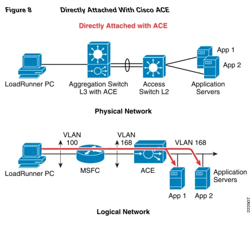
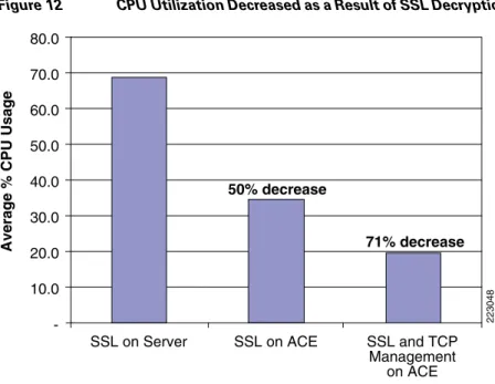
deployments, but Layer 7 load balancing can be used to support SSL termination and TCP reuse if necessary. For SSL encrypted deployments, the Cisco ACE module can off load server CPU utilization significantly. In addition, when coupled with TCP reuse feature, the Cisco ACE module can further reduce server CPU utilization. Test results for these two deployment modes is shown below. In this CPU utilization testing scenario, the PC running the HP Mercury LoadRunner was directly attached to the aggregation switch in the data center to generate 700 concurrent SSL-encrypted users connecting to a SharePoint page on the application server, through Cisco ACE to determine benefits of SSL off-load and TCP reuse. The Cisco ACE module performed Layer 4 load balancing to the MOSS servers for SSL termination on the server and then the Cisco ACE was reconfigured for Layer 7 load balancing to terminate SSL on the Cisco ACE module itself. An additional test was run with SSL termination on Cisco ACE with TCP reuse enabled to determine incremental benefits form this feature. As shown in the test results below, CPU utilization was decreased 50 percent with the termination of SSL encrypted traffic on the Cisco ACE. When TCP reuse was added, CPU utilization dropped another 21 percent, for a total of 71 percent CPU utilization savings. In these tests, the two application servers were each running two dual core 3.06 GHz CPUs with 1 GB of RAM.
Figure 8 Directly Attached With Cisco ACE
Test Results —Server CPU Statistics
Figure 9 SSL Terminated on Server
Figure 10 SSL Termination on Cisco ACE Module
Figure 11 SSL Termination on Cisco ACE Module with TCP reuse Directly Attached with ACE
Logical Network Physical Network 222907 Access Switch L2 Aggregation Switch L3 with ACE LoadRunner PC App 1 App 2 Application Servers ACE MSFC VLAN 100 VLAN 168 VLAN 168 LoadRunner PC Application Servers App 1 App 2
Figure 12 CPU Utilization Decreased as a Result of SSL Decryption and TCP Reuse on Cisco ACE
Implementing and Configuring the Cisco WAAS Solution
Implementation
Implementation Overview
The Cisco WAAS solution requires a minimum of three Cisco Wide Area Application Engine (WAE) appliances to auto-discover and deliver applicable application optimizations. One Cisco WAE is placed in the enterprise data center and the other at the branch site. The enterprise data center Cisco WAE is placed on the WAN edge connected to the WAN router. The third Cisco WAE is used for the Central Manager. The architecture offloads the Cisco WAE device from the local branch router and leverages the available ports on a local switch. This design provides scalability and availability for the solution.
What Was Implemented
Cisco WAAS technology requires the efficient and predictable interception of application traffic to produce results. It is critical that the Cisco WAE device see the entire TCP conversation. At the WAN edge, Cisco routers support the following four methods of traffic interception:
• Policy-based routing (PBR)
• Web Cache Communications Protocol (WCCP) v2
• Service policy with Cisco ACE
• Inline hardware
WCCPv2 is the most common method used in the remote branch environment; therefore, WCCPv2 has been leveraged for this solution.
223048 -80.0 70.0 60.0 50.0 40.0 30.0 20.0 10.0
SSL on Server SSL on ACE SSL and TCP Management
on ACE
50% decrease
71% decrease
Note Cisco WAEs “out of box” have a standard set of application variables and ports that are defined for optimization. In this solution no changes need to be made to the standard default configuration of the Cisco WAEs.
What Was Not Implemented
The following was not implemented in this solution:
• Cisco WAAS Network Module in which Cisco WAAS is installed in an integrated services router, providing a comprehensive solution within a single platform. This architecture provides less scalability and should be considered for use with a branch with small number of users.
Network Topology
Figure 13 Network Topology
WAN Simulation #1 Branch PC Access Aggregation WAN Edge Core Branch Site 222811 Edge Router Branch WAN WAN Cisco WAE LoadRunner Generator LoadRunner Controller Branch Cisco WAE Cisco WAAS CM dot1q trunk po 1 dot1q trunk
dot1q trunk dot1q trunk