MICRODOT and NANONICS Connectors
Tyco Electronics Corporation Harrisburg, Pennsylvania www.tycoelectronics.com
MICRODOT and
© Copyright 2001 and 2005 by Tyco Electronics Corporation. All Rights Reserved.
COMBOMATE, DUALOBE, JACKMATE, LEPRA/CON, MARC 53, MARC 63, MARC 73, MICRODOT, NANONICS, and TYCO are trademarks. Other products, logos, and Company names mentioned herein may be trademarks of their respective owners.
Disclaimer
While Tyco Electronics has made every reasonable effort to ensure the accuracy of the information in this catalog, Tyco Electronics does not guarantee that it is error-free, nor does Tyco Electronics make any other representation, warranty, or guarantee that the information is accurate, correct, reliable or current. Tyco Electronics reserves the right to make any adjustments to the information contained herein at any time without notice. Tyco Electronic expressly disclaims all implied warranties regarding the information contained herein, including but not limited to any implied warranties or merchantabili-ty or fitness for a particular purpose. It is recommended that you test any new or replacement product before incorporat-ing into a system.
The dimensions in this catalog are for reference purposes only and are subject to change without notice. Dimensions are in inches over [millimeters], unless other-wise specified. Always consult our customer drawings for recommended PC board layout and panel cutout dimensions; do not use catalog dimensions. Specifications are subject to change with-out notice.
Consult Tyco Electronics at 1-800-522-6752 for latest dimensions and design specifications, or use our global contact list shown on inside back cover.
MICRODOT
Connectors
NANONICS
i
Main Table of Contents
i
DUALOBE Rectangular Connectors . . . 141-178
Circular Connectors. . . 179-196
Coaxial Connectors . . . 197-206
Strip Connectors . . . 207-214
Part Number Index . . . 215-218
Microminiature D Connectors . . . 5-35
Rectangular Connectors . . . 37-54
Circular Connectors . . . 55-90
Coaxial Connectors . . . 91-136
MICRODOT
NANONICS
Engineering Notes
ii
Catalog 1308638 Dimensions are in inches and Dimensions are shown for USA: 1-800-522-6752 South America: 55-11-3611-1514 Revised 8-05 millimeters unless otherwise reference purposes only. Canada: 1-905-470-4425 Hong Kong: 852-2735-1628
specified. Values in brackets Specifications subject Mexico: 01-800-733-8926 Japan: 81-44-844-8013 www.tycoelectronics.com are metric equivalents. to change. C. America: 52-55-5-729-0425 UK: 44-141-810-8967
MICRODOT Connectors
Table of Contents
1
Microdot Introduction . . . 4
Microminiature D Connectors . . . 5-35
Introduction . . . 5
MCK/MCD/MCDM Series Metal and Plastic Shell Connectors . . . 6
How To Specify MCK and MCD Connectors. . . 7
Contact Arrangements . . . 8
MCK Series Metal Shell Connectors . . . 9
MCK Series Metal Shell Connectors Panel Mounting — Cutout Dimensions . . . 10
MCD Series Plastic Shell Connectors . . . 11, 12
MCD Series Plastic Shell Connectors Panel Mounting — Cutout Dimensions . . . 13
Mounting and Coupling Hardware . . . 14, 15
MCK Transition Blocks
RT1 — Right Angle . . . 16-18
ST1 — Straight. . . 19-21
MCK ST2 Series Straight Mount PCB Connectors . . . 22-24
MCDM Series Metal Shell Connectors . . . 25, 26
MCDM Series Metal Shell RF COMBOMATE Connectors . . . 27-29
MCDM Series Metal Shell Connectors Panel Mounting — Cutout Dimensions . . . 30
MIL-DTL-83513 Cross Reference . . . 31-35
Rectangular Connectors. . . 37-54
Introduction . . . 37
TWIST Pin Contact Data . . . 38
MCE Plastic
MCE Series Plastic Shell Edgeboard Connectors . . . 39-41
Technical & Performance Data. . . 39
Mother Board & Daughter Board Connectors . . . 40
How To Specify . . . 41
MCEM Metal Shell
MCEM Series Metal Shell Edgeboard Connectors . . . 42-45
Performance Data . . . 42
128 Layout Connector . . . 43, 44
How To Specify . . . 44
184 Layout Connector . . . 45
MCJ Plastic
MCJ Series Plastic Shell Center Jackscrew Connectors . . . 46, 47
10 & 14 Layout Connectors . . . 46
26, 38 & 46 Layout Connectors . . . 47
How To Specify . . . 47
Contact Arrangements . . . 47
MCJM Metal Shell
MCJM Series Metal Shell Center Jackscrew Connectors. . . 46, 48, 49
Technical & Performance Data. . . 48
Plug & Receptacle Connectors . . . 48, 49
How To Specify . . . 49
Table of Contents
(Continued)
2
Catalog 1308638 Dimensions are in inches and Dimensions are shown for USA: 1-800-522-6752 South America: 55-11-3611-1514 Revised 8-05 millimeters unless otherwise reference purposes only. Canada: 1-905-470-4425 Hong Kong: 852-2735-1628
specified. Values in brackets Specifications subject Mexico: 01-800-733-8926 Japan: 81-44-844-8013 www.tycoelectronics.com are metric equivalents. to change. C. America: 52-55-5-729-0425 UK: 44-141-810-8967
MCS .050 [1.27] Centerline
MCS Series Strip Connectors . . . 50
Strip Connectors. . . 50
How To Specify . . . 50
High Density Standard Module (HDSM) Connectors. . . 51-54
Circular Connectors. . . 57-92
Introduction . . . 55, 56
MARC 43
General Information . . . 57
Materials and Finishes . . . 57
Service & Performance Data . . . 57
Test Data . . . 58
Contact Arrangements . . . 58
Part Number & Ordering Information . . . 59
Polarizing Key Positions . . . 59
Shell Configurations. . . 60-62
Cable Clamps, Contacts, Sealing Plugs,
Protective Covers & Modifications . . . 63
MARC 53
General Information . . . 64
Materials and Finishes . . . 64
Service & Performance Data . . . 65
Test Data . . . 66
Contact Arrangements . . . 67
Part Number & Ordering Information . . . 67
Polarizing Key Positions . . . 68
Shell Configurations. . . 69-71
Test Adapters, Protective Covers, Cable Clamps
& Modifications . . . 72, 73
MARC 63
Performance Data. . . 74
Part Number & Ordering Information . . . 75
Shell Configurations . . . 75, 76
Cable Clamps, Protective Covers & Modifications . . . 77
MARC 43, 53, 63
Contacts & Sealing Plugs . . . 78-80
MARC 43, 53, 63, 73
Assembly Tools . . . 81
MARC 73
Service & Performance Data . . . 82, 83
Part Number & Ordering Information . . . 83
Shell Configurations . . . 84, 85
Cable Clamps, Contacts & Sealing Plugs . . . 85, 86
MQR Series – Microminiature Circular Connectors. . . 87, 88
MTC Series – Microminiature Circular Connectors . . . 89, 90
Table of Contents
(Continued)
3
Coaxial Connectors . . . 91-136
Introduction . . . 91
Standard Coaxial Connectors
Performance Data/Materials . . . 92
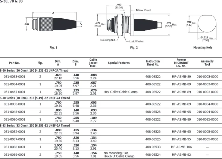
Screw-On Series (S) . . . 93-98
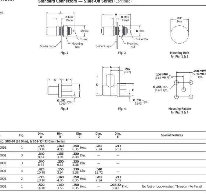
Slide-On Series (SOS) . . . 99-102
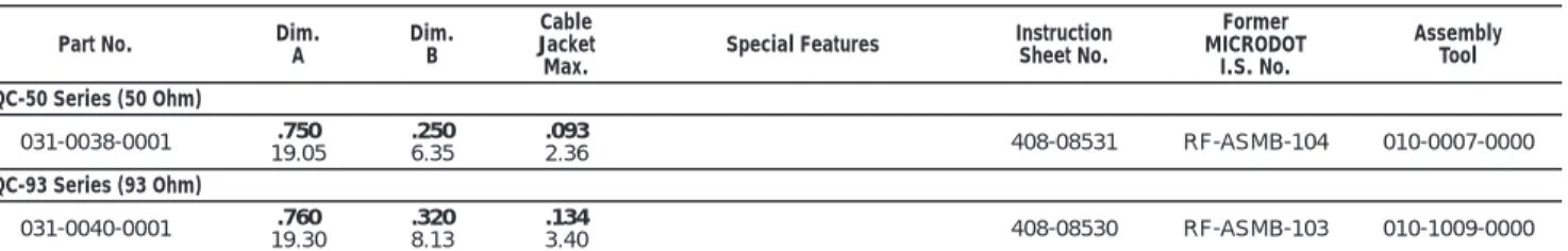
Quick-Connect Series (QC) . . . 103-105
Twinax Series . . . 106
Triax Series . . . 107
Terminals . . . 107
Module Blocks . . . 108
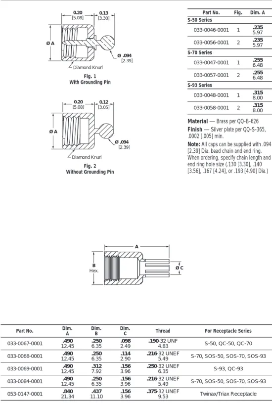
Caps For Screw-On Jacks and Receptacles . . . 109
Feed Thru Adapters, Screw-On . . . 110
BNC/TNC Adapters to:
Screw-On Series (S) . . . 110, 111
Slide-On Series (SOS) . . . 111
Quick-Connect (QC). . . 111
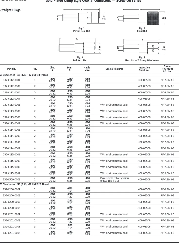
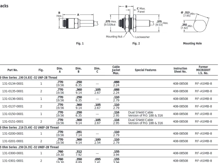
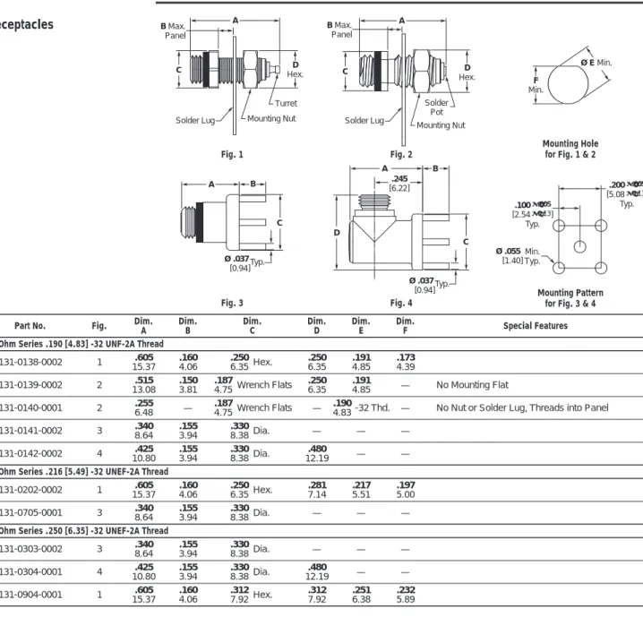
Gold Plated Crimp Style Coaxial Connectors
Performance Data/Materials . . . 112
Screw-On Series . . . 113-116
Assembly Tools . . . 116
LEPRA/CON Ultra Miniature Connectors
Performance Data/Materials . . . 117
Screw-On Series — Standard Interface . . . 118, 119
Screw-On Series — Locking Interface . . . 120, 121
Slide-On Series . . . 122, 123
Assembly Tools . . . 123
BNC / LEPRA/CON Adapters . . . 124, 125
Snap-Lock Series . . . 126
Cable Assemblies
Ordering Instructions . . . 127
Mating Interface Chart . . . 128
Cable Acceptance Dimensions
Standard Coaxial Connectors . . . 129-133
Gold Plated Crimp Style Coaxial Connectors . . . 133, 134
LEPRA/CON Connectors . . . 134
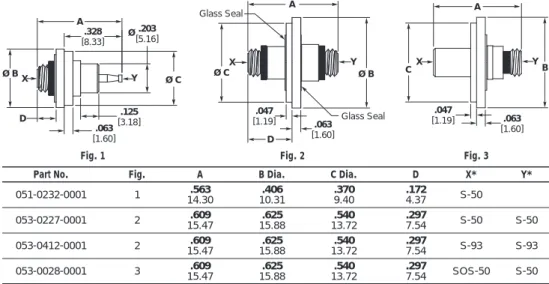
Hermetic Connectors
MICRODOT Introduction
4
Catalog 1308638 Dimensions are in inches and Dimensions are shown for USA: 1-800-522-6752 South America: 55-11-3611-1514 Revised 8-05 millimeters unless otherwise reference purposes only. Canada: 1-905-470-4425 Hong Kong: 852-2735-1628
specified. Values in brackets Specifications subject Mexico: 01-800-733-8926 Japan: 81-44-844-8013 www.tycoelectronics.com are metric equivalents. to change. C. America: 52-55-5-729-0425 UK: 44-141-810-8967
MICRODOT Connector
products have a fifty-year
heritage of leadership in
precision design and
manu-facturing of innovative and
cost-effective interconnects.
These innovative and
cost-effective products offer
interconnect solutions for a
broad range of applications
in the Aerospace, Military,
Medical, Instrumentation,
Communications and
Computer markets.
The MICRODOT reputation
for hands-on experienc
and outstanding technical
support is now enhanced
as part of Tyco Electronics
Corporation.
From standard Mil-Spec
configurations to custom
designs, we have the
Micro-D, subminiature and
ultra-miniature coaxial,
custom hermetic and
space-related cylindrical
connectors to meet your
need, whether it is
build-to-print assemblies, or total
turn-key assembly program
management. MICRODOT
connectors have met the
rigorous demands imposed
in manned space flight,
military and commercial
satellites, critical medical
applications, and
geo-physical exploration.
Microminiature D Connectors
5
Micr
ominiature
D
Connectors
1
MICRODOT Connectors
MCK and MCD High Density
Microminiature “D”
Connectors described in
this catalog comprise a
complete connector
sys-tem, which is adaptable to
a numerous variety of form
factors. Low engaging force
is achieved by the manner
in which the twist pin
contacts are designed.
By constructing the male
contact as a breathing
helical spring, electrical
contact is achieved at many
points around the periphery
of the pin bundle rather
than at a few discrete
points, as in conventional
pin designs. Normal twist
pin engagement force is
6 oz. [1.67N] typically and
8 oz. [2.22N] maximum. The
low force twist pins exhibit
an engaging force of 4 oz.
[1.11N] typically and 5 oz.
[1.39N] maximum. Low
force twist pins are standard
in MIL-DTL-83513
configu-rations of MCK and MCD
connectors and may be
supplied as an option in all
other configurations.
The MCK and MCD Series
of connectors featured in
this catalog are designed to
meet the applicable
require-ments of MlL-DTL-83513,
for intermateability,
inter-changeability, and
performance. Designed for
both military and
commer-cial applications, the MCK’s
and MCD’s are especially
well suited for use in
minia-turized airborne and space
electronics, computers, and
test equipment. The metal
shell MCK’s and plastic
shell MCD’s are available
with solder cup, and solid or
stranded wire terminations.
MCK transition blocks are
standard for printed circuit
board mounting. Custom
termination configurations
for both MCK and MCD
can be accommodated.
Micro D’s are also supplied
in wired harness assemblies.
Product Facts
n
Designed for both military
and commercial applications
n
Low engaging force is
achieved by the manner in
which Twist Pin Contacts are
designed
n
The metal shell and plastic
shell are available with
solder cup and solid or
stranded wire terminations
n
Mating force maximum is
10 oz. [2.78N] times the
number of contacts
n
Durability — No known
mechanical or electrical
issues detrimental to the
function of the connectors
after 500 cycles of mating
and unmating
n
Current Rating — 3 amps
max per contact
MCK/MCD/MCDM Series Metal and Plastic Shell Connectors
6
Catalog 1308638 Dimensions are in inches and Dimensions are shown for USA: 1-800-522-6752 South America: 55-11-3611-1514 Revised 8-05 millimeters unless otherwise reference purposes only. Canada: 1-905-470-4425 Hong Kong: 852-2735-1628
specified. Values in brackets Specifications subject Mexico: 01-800-733-8926 Japan: 81-44-844-8013 www.tycoelectronics.com are metric equivalents. to change. C. America: 52-55-5-729-0425 UK: 44-141-810-8967
Electrical
Contacts
— Pin 24 AWG twist pin,
Socket 24 AWG precision machined
barrel, Wire Range 24 AWG to 30 AWG
solid and stranded.
Contact Resistance
— (voltage drop)
25 millivolts max. at 3 amps, 77°± 7.4°F
[25°± 3° C].
Current Rating
— 3 amps max. per
contact.
Dielectric Withstanding Voltage
—
Volts RMS 60 Hz at room ambient.
At sea level 600V solder pots, 750V wire
terminations & transition blocks.
At 70,000 ft. [21,336 m] 150V solder
pots, 200V wire terminations &
transi-tion blocks.
Insulation Resistance
— 5,000
megohms min. (@ 500 VDC) at ambient
room temperature.
Magnetic Permeability
— 2 mu max.
Mechanical
Contact Spacing
— .050 [1.27mm]
centers.
Contact Engagement &
Separation
— Standard contact
engaging force is 6.0 oz. [1.67N] (8.0 oz.
[2.22N] max.). Separation force is 0.5
[.14N] oz. min.
Mating Force Maximum
—
Calculated as 10 oz. times the number
of contacts.
Environmental
Temperature Range
—
-67°F to 257°F [-55° C to +125°C] for
MCK/MCD, -67°F to 302°F [-55°C to
+150°C] for MCDM.
Vibration
— No discontinuity in
excess of 1 µ sec. when tested in
accor-dance with MIL-STD-1344, Method
2005, test Condition IV.
Solderability
— Connectors shall
pass the test requirements of
MIL-STD-202, Method 208
Shock
— No discontinuity in excess of
1 µ sec. when tested in accordance with
MIL-STD-1344, Method 2004, test
Condition E.
Durability
— No mechanical or
electri-cal defects detrimental to the function of
the connectors after 500 cycles of
mat-ing and unmatmat-ing.
Humidity
— After exposure to
humidi-ty as specified by MIL-STD-1344,
Method 1002, Type II, IR shall be 1
megohm min. following step 7a of
Method 1002 and 1000 megohms min.
after 24 hours of conditioning per
Method 1002.
Salt Spray
— Connectors shall meet
the performance requirements of contact
resistance, mating and unmating forces,
and contact retention after being
subject-ed to the 48-hour 5% solution salt spray
test per MIL-STD-1344, Method 1001,
Condition B.
Fluid Immersion
— Unmated
con-nectors after being fully immersed in one
of the following fluids, for the prescribed
time, will mate at a force of 10 oz.
[2.78N] times the number of contacts
or less: Perchloroethylene, 2 hours;
Lubricating oil per MIL-L-23699,
20 hours.
Insert Retention
— Inserts will
with-stand a 50 lb. [34N/cm
2] per square inch
load in either direction.
Crimp Termination Tensile
Strength
— (Unassembled contacts
with crimped stranded wire terminations)
Wires will not pull out of contacts when
the following axial loads are applied:
24 AWG, 5 lbs. [22.24N]; 26 AWG,
4 lbs. [17.79N]; 28 AWG, 3 lbs.
[13.34N]
Outgassing
— When tested in
accor-dance with SP-R-0022, Total Mass Loss
(TML) shall be less than 1.0% and
Volatile Condensable Material (VCM)
shall be less than 0.1% of the original
specimen.
Materials and Finishes
Contacts
— Copper alloy plated with
.000050 [.00127] gold over copper flash
per MIL-G-45204 Type II.
Hardware
— see pages 14 and 15.
MCK-Metal Shell
—
Insulator — Liquid crystal polymer
(LCP) per ASTM D5138, or
Polyphenylene sulfide GST-40F per
ASTM D5927 or MIL-M-24519
Interfacial Seal — Fluorosilicone Rubber
per MIL-R-25988 (socket side only)
Body Shell — Aluminum alloy-high
grade plated
Cadmium per QQ-P-416
Nickel, electroless per AMS 2404
Transition Block Shell
—
Liquid crystal polymer (LCP) per ASTM
D5138, or Polyphenylene sulfide
GST-40F per ASTM D5927 or
MIL-M-24519
Potting Material — Epoxy, Black
MCD-Plastic Shell
—
Insulator/Body — Polyester, glass filled
per MIL-M-24519, Liquid crystal
polymer (LCP) per ASTM D5138, or
Polyphenylene sulfide GST-40F per
ASTM D5927 or MIL-M-24519
Wire Terminations
—
Solid copper per QQ-W-343 gold plated
per MIL-G-45204
Stranded TEFLON insulated per
MIL-W-16878
Stranded TEFLON insulated per
MIL-W-22759/11, /33
Solid copper per QQ-W-343, solder
dipped (Transition block)
MCDM-Metal Shell
—
Insulator — Diallyl Phthalate per
MIL-M-14, Type SDG-F
Body Shell — Aluminum alloy—high
grade, nickel plated
Technical and Performance Data
(Applicable to MCK, MCD and MCDM unless otherwise noted)
MIL-DTL-83513 — Only the descriptive legend in bold italic is applicable to current MIL-DTL-83513 configurations; MIL-DTL-83513/1 through /4 — MCK metal shell; MIL-DTL-83513/6 through /9 — MCD plastic shell.
In addition, MIL-DTL-83513 solid copper wire termination is specified 25 AWG, 0.5; and 1.0 [25.4] lengths only and stranded insulated wire termination is specified 26 AWG, 18.0 [457.2] and 36.0 [914.4] lead lengths only. Hardware for MIL-DTL-83513 configurations is specified separately by the M83513/5-XX designation. M83513/1 through /4 and /6 through /9 specify no hardware (B). Mounting/mating hardware is shown on page 14 with the applicable military nomenclature. The MICRODOT catalog part number for a MIL-DTL-83513 configuration may be constructed to include the desired hardware.
See pages 31-35 for M83513/ cross reference.
Twist Pin, Pin and Socket
Contacts
The contact spring member
normally found in socket
contacts has been
eliminat-ed by creating a breathing
helical spring principle on
the pin contact — smaller,
more durable contacts
can be manufactured
economically.
How To Specify MCK and MCD Connectors
7
Micr
ominiature
D
Connectors
1
Metal Shell
Plastic Shell
MCK- C2 B 37 P 6 A 1 18.0Lead Length in Inches (Min.) X — Special, not described by legend.
Insulation Color or Finish
1 — All white wire 6 — Bare (unfinished)
2 — All yellow wire 7 — Color coded per MIL-STD-681, System 1 3 — All gray wire 8 — Special color code
4 — Gold plated 9 — 10 Solid color repeating per M-83513 5 — Tin dipped gold plated
Wire Type A — Type E, 7 strand B — Type ET, 7 strand C — Type E, 19 strand D — Type ET, 19 strand F — 7 strand per MIL-W-22759/11
(28 AWG only)
G — 19 strand per MIL-C-22759/11 (26 AWG only), 24 AWG L — Copper, Solid
(25 AWG only)
Q — Stranded per MIL-W-22759/33 (26 AWG only)
Wire Size
4 — 24 AWG 5 — 25 AWG 6 — 26 AWG 8 — 28 AWG 0 — 30 AWG Per MIL-W-16878
{
Connector Series
Shell Finish C1 — Cadmium, Clear
C2 — Cadmium, Yellow Chromate N1 — Nickel, Electroless
Hardware (See Pages 14 and 15)
B — No Hardware
F — Float Bushing
K, KM — Jackscrew, Slotted Head, High Profile (9-51) H, HM — Jackscrew, Slotted Head, High Profile (100) L, LM — Jackscrew, Slotted Head, Low Profile (9-51) J, JM — Jackscrew, Slotted Head, Low Profile (100) Q, QM — Jackscrew, Allen Head, High Profile (9-51) T, TM — Jackscrew, Allen Head, High Profile (100) R, RM — Jackscrew, Allen Head, Low Profile (9-51) N, NM — Jackscrew, Allen Head, Low Profile (100)
P — Jackpost Assembly (9-51) S — Jackpost Assembly (100)
X — Lockscrew, Slotted Head Y — Lockscrew, Allen Head Z — Clip and Key (Clip Mount Only) Layout
9, 15, 21, 25, 31, 37, 51, 100
See contact arrangement Contact Type
P — Pin (Plug) S — Socket (Receptacle)
S — Solder pots 26 AWG max.
MCD R3 B 37 P 6 A 1 18.0
Lead Length in Inches (Min.)
X — Special — Does not fit description below.
Insulation Color or Finish
1 — All white wire 6 — Bare (unfinished)
2 — All yellow wire 7 — Color coded per MIL-STD-681, System 1 3 — All gray wire 8 — Special color code
4 — Gold plated 9 — 10 Solid color repeating per M-83513 5 — Tin dipped gold plated
Wire Type A — Type E, 7 strand B — Type ET, 7 strand C — Type E, 19 strand D — Type ET, 19 strand F — 7 strand per MIL-W-22759/11
(28 AWG only)
G — 19 strand per MIL-C-22759/11 (26 AWG only), 24 AWG L — Copper, Solid
(25 AWG only)
Q — Stranded per MIL-W-22759/33 (26 AWG only)
Wire Size
4 — 24 AWG 5 — 25 AWG 6 — 26 AWG 8 — 28 AWG 0 — 30 AWG Per MIL-W-16878
{
Connector Series
Insulator Type/Material G2 — Clip Mount, polyester, natural G3 — Screw Mount, polyester, natural, .093 Flg. R2 — Clip Mount, Ryton
R3 — Screw Mount Liquid Crystal Polymer or Polyphenylene Sulfide
Hardware (See Pages 14 and 15)
B — No Hardware
F — Float Bushing
K, KM — Jackscrew, Slotted Head, High Profile L, LM — Jackscrew, Slotted Head, Low Profile Q, QM — Jackscrew, Allen Head, High Profile R, RM — Jackscrew, Allen Head, Low Profile
P — Jackpost Assembly
X — Lockscrew, Slotted Head Y — Lockscrew, Allen Head Z — Clip and Key (Clip Mount Only) Layout
9, 15, 21, 25, 31, 37, 51
See contact arrangement Contact Type
P — Pin (Plug) S — Socket (Receptacle)
S — Solder pots 26 AWG max.
Contact Arrangements
8
Catalog 1308638 Dimensions are in inches and Dimensions are shown for USA: 1-800-522-6752 South America: 55-11-3611-1514 Revised 8-05 millimeters unless otherwise reference purposes only. Canada: 1-905-470-4425 Hong Kong: 852-2735-1628
specified. Values in brackets Specifications subject Mexico: 01-800-733-8926 Japan: 81-44-844-8013 www.tycoelectronics.com are metric equivalents. to change. C. America: 52-55-5-729-0425 UK: 44-141-810-8967
Note: MCK metal shells are not designed to intermate or interchange with MCD plastic shells. If metal/plastic intermating is desired, use MCDM Series Metal
Shell on pages 25 and 26 with MCD Series Plastic Shell on page 11.
1 13 25 14 1 19 20 37 5 1 9 6 8 1 9 15 1 11 21 12 1 16 17 31 1 18 19 35 36 51 1 9 16 24 8 15 23 30 26 51 75 100 1 27 52 76 100 Contacts (MCK Only) 37 Contacts 51 Contacts 31 Contacts 30 Contacts (MCDM Only) 25 Contacts
9 Contacts 15 Contacts 21 Contacts
Face View of Pin Insert
(Socket Side is Mirror Image)
MCK Series Metal Shell Connectors
9
Micr
ominiature
D
Connectors
1
A C E FPart B Max. +.010 [.254] D Max
Number ± .010 [.254] -.018 [.457] ±.010 [.254] ± 005 [.127] MCK**- 9P*** 19.68.775 .33388.48 .3909.91 .2706.86 .2987.57 14.35.565 MCK**- 9S*** 19.68.775 .401810.21 .3909.91 .2706.86 .2987.57 14.35.565 MCK**- 15P*** 23.50.925 .483812.29 13.72.540 .2706.86 .2987.57 18.16.715 MCK**- 15S*** 23.50.925 .551814.02 13.72.540 .2706.86 .2987.57 18.16.715 MCK**- 21P*** 1.07527.30 .633816.10 17.53.690 .2706.86 .2987.57 21.97.865 MCK**- 21S*** 1.07527.30 .701818.05 17.53.690 .2706.86 .2987.57 21.97.865 MCK**- 25P*** 1.17529.84 .733818.64 20.07.790 .2706.86 .2987.57 24.51.965 MCK**- 25S*** 1.17529.84 .801820.37 20.07.790 .2706.86 .2987.57 24.51.965 MCK**- 31P*** 1.32533.66 .883822.45 23.88.940 .2706.86 .2987.57 1.11528.32 MCK**- 31S*** 1.32533.66 .951824.18 23.88.940 .2706.86 .2987.57 1.11528.32 MCK**- 37P*** 1.47537.46 1.033826.26 1.09027.69 .2706.86 .2987.57 1.26532.13 MCK**- 37S*** 1.47537.46 1.101827.99 1.09027.69 .2706.86 .2987.57 1.26532.13 MCK**- 51P*** 1.42536.20 .983824.99 1.04026.42 .3107.87 .3418.66 1.21530.86 MCK**- 51S*** 1.42536.20 1.051826.72 1.04026.42 .3107.87 .3418.66 1.21530.86 MCK**- 100P*** 2.16054.86 1.383835.15 1.43236.37 .3609.15 .3849.75 1.80045.71 MCK**- 100S*** 2.16054.86 1.50838.30 1.43236.37 .3609.15 .3849.75 1.80045.71 P = Pin, S = Socket
Dimensions per
MIL-DTL-83513
Plug (Pin side) Receptacle (Socket side) F Contact #1 Pin E A Two Mtg. Holes Pin B Pin D .183±.003 [4.65±0.08] .093±.005 [2.36±0.13] Ø.092±.004 [2.34±0.10] Ø.145 – .150 [3.68 – 3.81] .406±.010 [10.31±0.25] C Crimp or Solder Crimp or Solder Socket Socket Socket F Contact #1 E A .419±.010 [10.64±0.25] C .195±.003 [4.95±0.08] .093±.005 [2.36±0.13] D B (9-51 ) (100 ) Tw o Mtg. Holes Ø.092±.004 [2.34±0.10] Ø.145 – .150 [3.68 – 3.81] (9-51 ) (100 )MCK Series Metal Shell Connectors Panel Mounting — Cutout Dimensions
10
Catalog 1308638 Dimensions are in inches and Dimensions are shown for USA: 1-800-522-6752 South America: 55-11-3611-1514 Revised 8-05 millimeters unless otherwise reference purposes only. Canada: 1-905-470-4425 Hong Kong: 852-2735-1628
specified. Values in brackets Specifications subject Mexico: 01-800-733-8926 Japan: 81-44-844-8013 www.tycoelectronics.com are metric equivalents. to change. C. America: 52-55-5-729-0425 UK: 44-141-810-8967
Panel Mounting
Dimensions —
MCK
Plug and Receptacle Rear Mounted
Plug and Receptacle Front Mounted
Plug Front Mounted Receptacle Rear Mounted .200 [5.08] .395 [10.03] .300 [7.62] A A C C B B .095 [2.41] .095 [2.41] .122 [3.10] .122 [3.10] .015 [.381] Max. Typ. Full Radius (Typ.) Full Radius (Typ.) Full Radius (Typ.) Full Radius (Typ.) 116 Typ. R R 4 Plcs. 9-51 9-51 100 100 Figure 1 Front Mounting Figure 2 Rear Mounting Front Mounting Rear Mounting .015 [.381] .369/.364 [9.37/9.24] .403/.398 [10.24/10.11] 1.810/1.805 [45.98/45.85] 1.810/1.805 [45.98/45.85] 1.448 .002 [36.83/36.73] 1.514 .002 [38.51/38.40] Max. Typ. R .055 [1.40] Max. Typ. R + .005 – .000 + .127 – .000 .101 [2.56 ] Number A B C of Fig. + .004 [.102] + .004 [.102] + .005 [.127] Contacts – .000 [.000] – .000 [.000] – .000 [.000] 1 .404 .274 .570 9 10.26 6.96 14.48 2 10.31.406 .2576.53 14.48.570 1 .554 .274 .720 15 14.07 6.96 18.29 2 14.12.556 .2576.53 18.29.720 1 .704 .274 .870 21 17.88 6.96 22.10 2 17.93.706 .2576.53 22.10.870 1 .804 .274 .970 25 20.42 6.96 24.64 2 20.47.806 .2576.53 24.64.970 1 .954 .274 1.120 31 24.23 6.96 28.45 2 24.28.956 .2576.53 1.12028.45 1 1.104 .274 1.270 37 28.04 6.96 32.26 2 1.10628.09 .2576.53 1.27032.26 1 1.054 .314 1.220 51 26.77 7.98 30.99 2 1.05626.82 .3007.62 1.22030.99
MCD Series Plastic Shell Connectors
11
Micr
ominiature
D
Connectors
1
Part A C E F Avg. Weight
Number ± .010 [.254] B Max. +.010 [.254] D Max lbs. ± 5%
-.018 [.457] ±.010 [.254] ± 005 [.127] [grams] MCD**- 9P*** 19.76.778 .29187.412 10.11.398 .1734.39 .2085.28 14.35.565 .00170.77 MCD**- 9S*** .778 .3798 .398 .173 .208 .565 .0016 19.76 9.647 10.11 4.39 5.28 14.35 0.72 MCD**- 15P*** 23.57.928 11.222.4418 13.92.548 .1734.39 .2085.28 18.16.715 .00241.08 MCD**- 15S*** .928 .5298 .548 .173 .208 .715 .0023 23.57 13.457 13.92 4.39 5.28 18.16 1.04 MCD**- 21P*** 1.07827.38 15.032.5918 17.73.698 .1734.39 .2085.28 21.97.865 .00351.59 MCD**- 21S*** 1.078 .6798 .698 .173 .208 .865 .0034 27.38 17.267 17.73 4.39 5.28 21.97 1.54 MCD**- 25P*** 1.17829.92 17.572.6918 20.27.798 .1734.39 .2085.28 24.51.965 .00421.90 MCD**- 25S*** 1.178 .7798 .798 .173 .208 .965 .0037 29.92 19.807 20.27 4.39 5.28 24.51 1.67 MCD**- 31P*** 1.32833.73 21.382.8418 24.08.948 .1734.39 .2085.28 1.11528.32 .00532.40 MCD**- 31S*** 1.328 .9298 .948 .173 .208 1.115 .0048 33.73 23.617 24.08 4.39 5.28 28.32 2.17 MCD**- 37P*** 1.47837.54 25.192.9918 1.09827.89 .1734.39 .2085.28 1.26532.13 .00572.58 MCD**- 37S*** 1.478 1.0798 1.098 .173 .208 1.265 .0051 37.54 27.427 27.89 4.39 5.28 32.13 2.31 MCD**- 51P*** 1.42836.27 23.922.9418 1.04826.62 .2205.59 .2506.35 1.21530.86 .00723.26 MCD**- 51S*** 1.428 1.0298 1.048 .220 .250 1.215 .0063 36.27 26.157 26.62 5.59 6.35 30.86 2.85 P = Pin, S = Socket
Note:Weight given is with .500 [12.7] uninsulated, solid, 24 AWG gold plated copper pigtails. *See “How to Specify” for description, on page 7.
Screw Mount
Dimensions Per
MIL-DTL-83513
Plug (Pin side) Receptacle (Socket side) F Contact #1 Pin E A Two Mtg. Holes Pin B Pin D .199±.005 [5.05±.13] .094±.006 [2.39±0.15] Ø.092±.004 [2.34±.10] .395 /.360 [10.0 3/9.14] C Crimp or Solder Crimp or Solder F Contact #1 E A T w o Mtg. Holes Ø.092±.004 [2.34±0.10] .375 /.340 [9.52/8.64] C .180±.005 [4.57±0.13] .094±.006 [2.39±0.15] D B Socket Socket SocketLiquid Crystal Polymer or
Polyphenylene Sulfide — MCDR3* per
MIL-DTL-83513
MCD Series Plastic Shell Connectors
(Continued)
12
Catalog 1308638 Dimensions are in inches and Dimensions are shown for USA: 1-800-522-6752 South America: 55-11-3611-1514 Revised 8-05 millimeters unless otherwise reference purposes only. Canada: 1-905-470-4425 Hong Kong: 852-2735-1628
specified. Values in brackets Specifications subject Mexico: 01-800-733-8926 Japan: 81-44-844-8013 www.tycoelectronics.com are metric equivalents. to change. C. America: 52-55-5-729-0425 UK: 44-141-810-8967
Part A C D E Avg. Weight
Number ±.005 [.127] B Max. ±.010 [.254] ±.010 [.254] ±.005 [.127] lbs. ± 5% [grams] MCD**- 9P*** 12.85.506 .291874.12 10.11.398 .1654.19 .2085.28 .00170.77 MCD**- 9S*** .506 .3798 .398 .165 .208 .0016 12.85 96.47 10.11 4.19 5.28 0.72 MCD**- 15P*** 16.66.656 112.22.4418 13.92.548 .1654.19 .2085.28 .00241.08 MCD**- 15S*** .656 .5298 .548 .165 .208 .0023 16.66 134.57 13.92 4.19 5.28 1.04 MCD**- 21P*** 20.47.806 150.32.5918 17.73.698 .1654.19 .2085.28 .00351.59 MCD**- 21S*** .806 .6798 .698 .165 .208 .0034 20.47 172.67 17.73 4.19 5.28 1.54 MCD**- 25P*** 23.01.906 175.72.6918 20.27.798 .1654.19 .2085.28 .00421.90 MCD**- 25S*** .906 .7798 .798 .165 .208 .0037 23.01 198.07 20.27 4.19 5.28 1.67 MCD**- 31P*** 1.05626.82 213.82.8418 24.08.948 .1654.19 .2085.28 .00532.40 MCD**- 31S*** 1.056 .9298 .948 .165 .208 .0048 26.82 236.17 24.08 4.19 5.28 2.17 MCD**- 37P*** 1.20630.63 251.92.9918 1.09827.89 .1654.19 .2085.28 .00572.58 MCD**- 37S*** 1.206 1.0798 1.098 .165 .208 .0051 30.63 274.27 27.89 4.19 5.28 2.31 MCD**- 51P*** 1.15629.36 239.22.9418 1.04826.62 .2085.28 .2506.35 .00723.26 MCD**- 51S*** 1.156 1.0298 1.048 .208 .250 .0063 29.36 261.57 26.62 5.28 6.35 2.85 P = Pin, S = Socket
Note:Weight given is with .500 [12.7] uninsulated, solid, 24 AWG gold plated copper pigtails. *See “How to Specify” for description, on page 7.
Clip Mount — MCD
Plug (Pin side) Receptacle (Socket side) Contact #1 Pin E A Pin B Pin D .199 [5.05] .395 /.360 [10.03 /9.14] C Crimp or Solder Crimp or Solder .093 ±.003 [2.44 /2.29] Contact #1 Socket E A Socket B Socket D .180 [4.57] .375 /.340 [9.52 /8.64] C .093 ±.003 [2.44 /2.29] .019 [.483] .019 [.483] .060 [1.52] .060 [1.52] Note: Clip Mount not covered byMCD Series Plastic Shell Connectors Panel Mounting — Cutout Dimensions
13
Micr
ominiature
D
Connectors
1
Panel Mounting Dimensions — MCD
Clip Mount
Screw Mount
Plug and Receptacle Rear Mounted
.200±.005
[5.08±0.13]
Plug and Receptacle Front Mounted
Plug Front Mounted Receptacle Rear Mounted
.330±.005
[8.38±0.13]
.265±.005
[6.73±0.13]
Plug and Receptacle Rear Mounted
.200±.005
[5.08±0.13]
Plug and Receptacle Front Mounted
Plug Front Mounted Receptacle Rear Mounted
.395±.005 [10.03±0.13] .300±.005 [7.62±0.13] Front Full Radius (Typ.) R R A A C B Figure 2 Front Figure 1 Rear Figure 4 Rear Figure 3 B B Full Radius (Typ.) 116 Typ. A C + .005 – .000 + 0.13 – 0.00 .089 [2.26 ] + .005 – .000 + 0.13 – 0.00 .075 [1.90 ] .015 [.381] Max. Typ. R.015 [.381] .089 [2.26] Max. Typ. B A R.015 [.381] Max. Typ. Number A B C of Fig. + .004 [.102] + .004 [.102] + .005 [.127] Contacts – .000 [.000] – .000 [.000] – .000 [.000] 1 .438 [11.13] .177 [4.50] — 9 2 .412 [10.46] .177 [4.50] .570 [14.48] 3 .438 [11.13] .222 [5.64] — 4 .384 [9.75] .222 [5.64] .570 [14.48] 1 .588 [14.93] .177 [4.50] — 15 2 .562 [14.27] .177 [4.50] .720 [18.29] 3 .588 [14.93] .222 [5.64] — 4 .534 [13.56] .222 [5.64] .720 [18.29] 1 .738 [18.75] .177 [4.50] — 21 2 .712 [18.08] .177 [4.50] .870 [22.10] 3 .738 [18.75] .222 [5.64] — 4 .684 [17.37] .222 [5.64] .870 [22.10] 1 .838 [21.29] .177 [4.50] — 25 2 .812 [20.62] .177 [4.50] .970 [24.64] 3 .838 [21.29] .222 [5.64] — 4 .784 [19.91] .222 [5.64] .970 [24.64] 1 .988 [25.10] .177 [4.50] — 31 2 .962 [24.43] .177 [4.50] 1.120 [28.45] 3 .988 [25.10] .222 [5.64] — 4 .934 [23.72] .222 [5.64] 1.120 [28.45] 1 1.138 [28.91] .177 [4.50] — 37 2 1.112 [28.24] .177 [4.50] 1.270 [32.26] 3 1.138 [28.91] .222 [5.64] — 4 1.084 [27.53] .222 [5.64] 1.270 [32.26] 1 1.088 [27.64] .224 [5.69] — 51 2 1.062 [26.97] .224 [5.69] 1.220 [30.99] 3 1.088 [27.64] .264 [6.71] — 4 1.034 [26.26] .264 [6.71] 1.220 [30.99]
Panel Cutout Dimensions — MCD
Clip Mounting
Screw Mounting
Mounting and Coupling Hardware
14
Catalog 1308638 Dimensions are in inches and Dimensions are shown for USA: 1-800-522-6752 South America: 55-11-3611-1514 Revised 8-05 millimeters unless otherwise reference purposes only. Canada: 1-905-470-4425 Hong Kong: 852-2735-1628
specified. Values in brackets Specifications subject Mexico: 01-800-733-8926 Japan: 81-44-844-8013 www.tycoelectronics.com are metric equivalents. to change. C. America: 52-55-5-729-0425 UK: 44-141-810-8967
Ø .156 [3.96] Max. Over Knurl Jackscrew .086-56UNC-2A [2.18] Retaining Ring .853±.015 [21.67±0.38] .600 [15.24]
For Screw Mount MCK,
MCD and MCDM
9-51 Contacts
Slot Head
(K) (KM) Part Number 5-1532137-8 Jackscrew Assembly High Profile (K) 096-0002-0010 M83513/5-06 (KM) S96-0002-0084 Ø .125 [3.18] Jackscrew .086-56UNC-2A [2.18] Retaining Ring .340–.360 [8.64–9.14] .098 [2.29] (L) (LM) Part Number 5-1532137-7 Jackscrew Assembly Low Profile (L) 096-0002-0011 M83513/5-05 (LM) S96-0002-0085 Lockwasher Bushing .086-56UNC-2A [2.18] .086-56UNC-2B [2.18] Hex Nut .475 [12.07] .187 [4.75] Hex. .125 [3.18] (P) Part Number 5-1532137-9 Jackpost Assembly (P) S96-0002-0009 M83513/5-07 P mates with K,KM, L,LM, Q,QM and R,RM Jackscrew Assemblies.Ø .156 [3.96] Max. Over Knurl Jackscrew .086-56UNC-2A [2.18] Retaining Ring .853±.015 [21.67 ±0.38] .600 [15.24]
9-51 Contacts
1/16" Allen Head
(Q) (QM) Part Number 5-1532137-6 Jackscrew Assembly High Profile (Q) 096-0002-0014 M83513/5-03 (QM) S96-0002-0086 Ø .125 [3.18] Jackscrew .086-56UNC-2A [2.18] Retaining Ring .340–.360 [8.64–9.14] .098 [2.29] (R) (RM) Part Number 5-1532137-5 Jackscrew Assembly Low Profile (R) 096-0002-0015 M83513/5-02 (RM) S96-0002-0087 Ø .200 [3.96] Max. Over Knurl Max. Jackscrew .112-40UNC-2A [2.84] Retaining Ring .920 [23.37] .585 [14.86]100 Contacts
Slot Head
(H) (HM) Part Number 6-1532137-3 Jackscrew Assembly High Profile (H) 096-0002-0061 M83513/5-16 (HM) S96-0002-0088 Ø .187 [4.75] Jackscrew Max. .112-40UNC-2A [2.84] Retaining Ring .415 [10.54] .100 [2.54] (J) (JM) Part Number 6-1532137-2 Jackscrew Assembly Low Profile (J) 096-0002-0062 M83513/5-15 (JM) S96-0002-0089 Lockwasher Bushing .112-40UNC-2A [2.84] .112-40UNC-2B [2.84] Hex Nut .475 [12.07] Max. .185 [4.70] Hex. .187 [4.75] (S) Part Number 6-1532137-4 Jackpost Assembly (S) S96-0002-0060 M83513/5-17 S mates with H,HM, J,JM, T,TM and N,NM Jackscrew Assemblies. Ø .200 [3.96] Max. Over Knurl Max. Jackscrew .112-40UNC-2A [2.84] Retaining Ring .920 [23.37] .585 [14.86]100 Contacts
1/16" Allen Head
(T) (TM) Part Number 6-1532137-1 Jackscrew Assembly High Profile (T) 096-0002-0064 M83513/5-13 (TM) S96-0002-0090 Ø .187 [4.75] Jackscrew Max. .112-40UNC-2A [2.84] Retaining Ring .415 [10.54] .100 [2.54] (N) (NM) Part Number 6-1532137-0 Jackscrew Assembly Low Profile (N) 096-0002-0065 M83513/5-12 (NM) S96-0002-0091 Notes:1. Jackpost Assemblies will accom-modate .094 [2.39] max. thick-ness panel.
2. Letter(s) in parentheses is to assist in ordering hardware with the con-nector (See “How To Specify” page 7).
3. Single letters (e.g. K) designate hardware kits (2 pcs. per kit) that meets M83513/05 requirements except the material is 303 stain-less steel, passivated. 4. Add M suffix (e.g. KM) to
desig-nate hardware that meets all M83513/05 requirements. Material is corrosion resistant steel, non-magnetic, 125,000 PSI tensile strength minimum (Applies to jackscrews only).
5. Non-MIL hardware ordered sepa-rately should be ordered in pairs; i.e. 2 pcs. P/N 096-0002-0009 per connector half.
6. Items in bold italic are qualified to MIL-DTL-83513.
Mounting and Coupling Hardware
(Continued)
15
Micr
ominiature
D
Connectors
1
.356 [9.04] .600 [15.24]For Clip Mount — MCD
(Z)(X)
Part Number 1466018-1 Mounting Key and Clip P/N 096-0001-0000 (2 Required) .075 [1.91] Ø .125 [3.18] Retaining Clip .086 [2.18] -56UNC-2A Lockscrew Part Number 4-1532137-3 Lockscrew Assembly 096-0002-0008 .075 [1.91] Ø .125 [3.18] Lockscrew Retaining Clip .086 [2.18] .343 ±.010 [8.71 ±0.25] -56UNC-2A Part Number 1495164-1 Lockscrew Assembly 096-0002-0013
Slot Head
1/16" Allen Head
Notes:
1. Jackpost Assemblies will accommodate .094 [2.39] max. thickness panel.
2. Letter(s) in parentheses is to assist in ordering hardware with the connector (See “How To Specify” page 7). 3. Hardware ordered separately should be ordered in pairs; i.e. 2 pcs. P/N 096-0002-0013 per connector half.
For Screw Mount MCK,
MCD and MCDM
(Continued)
(Y)For Float Mount — MCK,
MCD and MCDM
(F)
Float Mount Bushing (Factory Installed)
Washer
MCK Transition Blocks
16
Catalog 1308638 Dimensions are in inches and Dimensions are shown for USA: 1-800-522-6752 South America: 55-11-3611-1514 Revised 8-05 millimeters unless otherwise reference purposes only. Canada: 1-905-470-4425 Hong Kong: 852-2735-1628
specified. Values in brackets Specifications subject Mexico: 01-800-733-8926 Japan: 81-44-844-8013 www.tycoelectronics.com are metric equivalents. to change. C. America: 52-55-5-729-0425 UK: 44-141-810-8967
RT1 — Right-Angle
Termination Configuration
Notes:
1. For terminal identification see page 18.
2. Grid pattern for all configurations is .100 x .100 [2.54 x 2.54]. 3. Lead lengths shown are for RT1.
4. Items in bold italic are qualified to MIL-DTL-83513.
.109 ±.015
[2.77 ±0.39]
.185
[4.70]
9, 15, 21 & 25 Contacts 31, 37, 51 & 100 Contacts
Contact #1 (Socket Connectors) Optional Jackpost (2 Plcs.)
For 9 Thru 51: .086-56 UNC-2B For 100: .112-40 UNC-2B Mounting Surface Mounting Surface Max. (Size 100 only) .190 [4.83] Max. (Sizes 9-51) .096±.003 [2.44±0.08] Dia. Typ. .125±.003 [3.18±0 .08] Dia. Typ. Mounting Surface Contact #1 (Pin Connectors) A B C D E F E F H G G (Size 100 Only) .096±.003 [2.44±0 .08] Dia. Typ.
MIL-DTL-83513/10 through /21
configurations. 90° — Lo Profile
termination configurations.
See pages 31-35 for M83513
cross references.
How To Specify
MCK C2 P 37 P RT1Right Angle Termination (Solder Dipped) RT1 — w/ .109 Leads RT1A — w/ .140 Leads RT1B — w/ .172 Leads Contact Type S = STD Socket P = STD Pin Layout 9, 15, 21, 25, 31, 37, 51 and 100 Hardware P = Jackpost (9-51) B = No Hardware S = (100) Shell Finish
C2 = Cadmium, Yellow Chromate N1 = Nickel, Electroless Connector Series
MCK Transition Blocks
(Continued)
17
Micr
ominiature
D
Connectors
1
RT1 — Right-Angle
Termination Configuration
(Continued)
Part Number Max.A ± 005 [.127]B Max.C Max.D Max.E +.010 [.254]F +.010 [.254]G Max.H
MCK-**- *- 9PRT1 .787 .565 .3338 .308 .425 .250 .230 — 19.99 14.35 8.48 7.83 10.80 6.35 5.84 MCK-**- *- 9SRT1 19.99.787 14.35.565 .401810.21 .3087.83 10.80.425 .2506.35 .2305.84 — MCK-**- *- 15PRT1 .937 .715 .4838 .308 .425 .250 .130 — 23.80 18.16 12.29 7.83 10.80 6.35 3.30 MCK-**- *- 15SRT1 23.80.937 18.16.715 .551814.02 .3087.83 10.80.425 .2506.35 .1303.30 — MCK-**- *- 21PRT1 1.087 .865 .6338 .308 .425 .250 .130 — 27.61 21.97 16.10 7.83 10.80 6.35 3.30 MCK-**- *- 21SRT1 1.08727.61 21.97.865 .701817.83 .3087.83 10.80.425 .2506.35 .1303.30 — MCK-**- *- 25PRT1 1.187 .965 .7338 .308 .425 .250 .130 — 30.15 24.51 18.64 7.83 10.80 6.35 3.30 MCK-**- *- 25SRT1 1.18730.15 24.51.965 .801820.37 .3087.83 10.80.425 .2506.35 .1303.30 — MCK-**- *- 31PRT1 1.337 1.115 .8838 .308 .525 .250 .130 1.090 33.96 28.32 22.45 7.83 13.34 6.35 3.30 27.69 MCK-**- *- 31SRT1 1.33733.96 1.11528.32 .951824.18 .3087.83 13.34.525 .2506.35 3.30.130 1.09027.69 MCK-**- *- 37PRT1 1.487 1.265 1.0338 .308 .525 .250 .130 1.190 37.77 32.13 26.26 7.83 13.34 6.35 3.30 30.23 MCK-**- *- 37SRT1 1.48737.77 1.26532.13 1.101827.99 .3087.83 13.34.525 .2506.35 3.30.130 1.19030.23 MCK-**- *- 51PRT1 1.435 1.215 .9838 .351 .660 .300 .150 1.230 36.45 30.86 24.99 8.92 16.76 7.62 3.81 31.24 MCK-**- *- 51SRT1 1.43536.45 1.21530.86 1.051826.72 .3518.92 16.76.660 .3007.62 3.81.150 1.23031.24 MCK-**- *- 100PRT1 2.175 1.800 1.3838 .394 1.010 .400 .200 1.825 55.25 45.72 35.15 10.01 25.65 10.16 5.08 46.36 MCK-**- *- 100SRT1 2.17555.25 1.80045.72 1.50838.30 10.01.394 1.01025.65 10.16.400 5.08.200 1.82546.36 P = Pin, S = Socket
MCK Transition Blocks
(Continued)
18
Catalog 1308638 Dimensions are in inches and Dimensions are shown for USA: 1-800-522-6752 South America: 55-11-3611-1514 Revised 8-05 millimeters unless otherwise reference purposes only. Canada: 1-905-470-4425 Hong Kong: 852-2735-1628
specified. Values in brackets Specifications subject Mexico: 01-800-733-8926 Japan: 81-44-844-8013 www.tycoelectronics.com are metric equivalents. to change. C. America: 52-55-5-729-0425 UK: 44-141-810-8967
RT1 — Right-Angle
Termination Configuration
(Continued)
View is from mounting surface of
connector. Plug configuration shown.
For receptacle, use mirror image.
(Except 100 contacts)
12 11 10 8 6 4 3 2 25 23 21 20 19 18 16 14 13 24 22 9 7 5 17 15 1 11 9 7 17 4 14 1 21 20 19 18 16 15 13 12 10 8 6 5 3 2 7 5 4 2 8 6 12 3 1 15 14 13 11 10 9 17 15 13 11 27 8 6 4 2 18 16 14 12 10 9 7 5 3 1 35 33 31 29 46 43 41 25 23 21 19 34 32 30 28 45 42 26 24 22 20 51 50 49 48 47 44 40 39 38 37 36 5 4 2 1 9 8 3 7 6 36 34 32 30 27 25 2 21 37 35 33 31 29 28 26 24 22 20 19 17 15 13 11 9 7 5 3 1 18 16 14 12 10 8 6 4 2 15 13 11 9 8 6 4 2 16 14 12 10 24 7 5 3 1 30 29 27 25 23 21 9 17 3 28 26 22 20 18 2 4 6 8 10 12 14 16 18 20 22 24 26 77 79 81 83 85 87 89 91 93 95 97 99 1 3 5 7 9 11 13 15 17 19 21 23 25 27 29 31 33 35 37 39 41 43 45 47 49 51 28 30 32 34 36 38 40 42 44 46 48 50 52 54 56 58 60 62 64 66 68 70 72 74 53 55 57 59 61 63 65 67 69 71 73 75 76 78 80 82 84 86 88 90 92 94 96 98 100 25 23 21 19 17 15 13 11 9 7 5 3 1 26 24 22 20 18 16 14 12 10 8 6 4 2 51 49 47 45 43 41 39 37 35 33 31 29 27 50 48 46 44 42 40 38 36 34 32 30 28 75 73 71 69 67 65 63 61 59 57 55 53 74 72 70 68 66 64 62 60 58 56 54 52 100 98 96 94 92 90 88 86 84 82 80 78 76 99 97 95 93 91 89 87 85 83 81 79 77 CL CL CL .100 [2.54]Typ. .050 [1.27] .020 [0.51] .020 [0.51] .020 [0.51] .083 [2.11] Typ. Typ. [2.54].100 .158 [4.01] Typ. CL CL CL CL CL .100 [2.54]Typ. .050 [1.27] .108 [2.74] .020 [0.51] .020 [0.51] .183 [4.65] .100 [2.54]Typ. .100 [2.54]Typ. 1.800 [45.72]Ref. .275 [6.99]Ref. .100 [2.54] Typ. Ref. .100 [2.54]Typ. .100 [2.54]Ref. Socket #1 Ref. (Receptacle Connector) .025 [0.64]Ref. .050 [1.27] Typ. Ref. 1.800 [45.72]Ref. .275 [6.99]Ref. .100 [2.54] Typ. Ref. .100 [2.54]Ref. .050 [1.27] Typ. Ref. .050 [1.27] Typ. .050 [1.27] Typ. .050 [1.27] .100 [2.54] .050 [1.27] .108 [2.74] Typ. Typ. .050 [1.27] .083 [2.11] Typ. 9 Contacts 31 Contacts 37 Contacts 100 Contacts (Socket Connector) .100 [2.54]Ref. Pin #1 Ref. (Plug Connector) .025 [0.64]Ref. 100 Contacts (Pin Connector) 51 Contacts .100 [2.54]Typ. .050 [1.27] .020 [0.51] .083 [2.11] Typ. 21 Contacts 25 Contacts 15 Contacts CL 1.266 [32.16]Ref. 1.216 [30.89]Ref. .966 [24.54]Ref. 1.116 [28.35]Ref. .866 [22.00]Ref. .716 [18.19]Ref. .566 [14.38]Ref.MCK Transition Blocks
(Continued)
19
Micr
ominiature
D
Connectors
1
How To Specify
ST1 — Straight
Termination Configuration
.185 [4.70] .190 [4.83] Max. (Sizes 9-51) (Sizes 9-51)Max. (Size100 only)
.550 [13.97]Max. .355 [9.02]Max. .100 [2.54]Typ. .050 [1.27]Typ. .165 [4.20]Max. (Sizes 9-51) .303
[7.70]Max. (Size 100 only)
.096±.003
[2.44±.076] Dia. Typ.(For Size 9 Thru 51)
.125±.003
[3.18±.076] Dia. Typ. (For Size 100 Only) Contact #1 (Socket Connector) Contact #1 (Pin Connector) Lead #1 (Pin Connector) Lead #1 (Socket Connector) Optional Jackpost (2 Plcs.) For 9 Thru 51: .086-56 UNC-2B
For 100: .112-40 UNC-2B A B F C D E .109 ±.015 [2.77 ±0.39] (Lead Length For ST1 Shown) (Size100 only)
MIL-DTL-83513/22 through /27
configurations. 180° — Lo Profile
termination configurations.
See page 35 for M83513 cross
references.
MCK C2 P 37 P ST1
Straight Termination (Solder Dipped) ST1 — w/ .109 Leads ST1A — w/ .140 Leads ST1B — w/ .172 Leads Contact Type S = STD Socket P = STD Pin Layout 9, 15, 21, 25, 31, 37, 51 and 100 Hardware P = Jackpost (9-51) B = No Hardware S = (100) Shell Finish
C2 = Cadmium, Yellow Chromate N1 = Nickel, Electroless Connector Series
(See page 9)
Notes:
1. For terminal identification see page 5048.
2. Grid pattern for all configurations is .100 x .100 [2.54 x 2.54]. 3. Lead lengths shown are for ST1.
MCK Transition Blocks
(Continued)
20
Catalog 1308638 Dimensions are in inches and Dimensions are shown for USA: 1-800-522-6752 South America: 55-11-3611-1514 Revised 8-05 millimeters unless otherwise reference purposes only. Canada: 1-905-470-4425 Hong Kong: 852-2735-1628
specified. Values in brackets Specifications subject Mexico: 01-800-733-8926 Japan: 81-44-844-8013 www.tycoelectronics.com are metric equivalents. to change. C. America: 52-55-5-729-0425 UK: 44-141-810-8967
Part Number Max.A ± .007 [.178]B ± .005 [.127]C Max.D Max.E Max.F
MCK-**- *- 9PST1 1.39035.31 1.15029.21 14.35.565 22.48.885 .33388.48 .3087.83 MCK-**- *- 9SST1 1.39035.31 1.15029.21 14.35.565 22.48.885 .401810.21 .3087.83 MCK-**- *- 15PST1 1.39035.31 1.15029.21 18.16.715 24.00.945 .483812.29 .3087.83 MCK-**- *- 15SST1 1.39035.31 1.15029.21 18.16.715 24.00.945 .551814.02 .3087.83 MCK-**- *- 21PST1 1.69042.93 1.45036.83 21.97.865 1.18530.10 .633816.10 .3087.83 MCK-**- *- 21SST1 1.69042.93 1.45036.83 21.97.865 1.18530.10 .701817.83 .3087.83 MCK-**- *- 25PST1 1.74044.20 1.50038.10 24.51.965 1.27532.39 .733818.64 .3087.83 MCK-**- *- 25SST1 1.74044.20 1.50038.10 24.51.965 1.27532.39 .801820.37 .3087.83 MCK-**- *- 31PST1 2.04051.82 1.80045.72 1.11528.32 1.57540.01 .883822.45 .3087.83 MCK-**- *- 31SST1 2.04051.82 1.80045.72 1.11528.32 1.57540.01 .951824.18 .3087.83 MCK-**- *- 37PST1 2.34059.44 2.10053.34 1.26532.13 1.87547.63 1.033826.26 .3087.83 MCK-**- *- 37SST1 2.34059.44 2.10053.34 1.26532.13 1.87547.63 1.101827.99 .3087.83 MCK-**- *- 51PST1 2.27057.66 2.00050.80 1.21530.86 1.77545.09 .983824.99 .3518.92 MCK-**- *- 51SST1 2.28057.91 2.00050.80 1.21530.86 1.77545.09 1.051826.72 .3518.92 MCK-**- *- 100PST1 3.25082.55 2.80071.12 1.80045.72 2.58565.66 1.383835.15 11.68.460 MCK-**- *- 100SST1 3.25082.55 2.80071.12 1.80045.72 2.58565.66 1.50838.30 11.68.460 P = Pin, S = Socket
ST1 — Straight Termination
Configuration
(Continued)
MCK Transition Blocks
(Continued)
21
Micr
ominiature
D
Connectors
1
ST1 — Straight Termination
Configuration
(Continued)
View is from mounting surface of
connector. Plug configuration shown.
For receptacle, use mirror image.
1 5 6 9 17 31 1 16 20 37 1 19 9 15 1 8 12 21 1 11 14 25 1 13 36 51 19 35 1 18 76 100 52 75 27 51 1 26 CL CL CL CL CL .100 [2.54]Typ. .050 [1.27] CL CL CL .100 [2.54]Typ. .050 [1.27] .050 [1.27] .050 [1.27] .375 [9.53] .225 [5.72] .050 [1.27] .225 [5.72] .050 [1.27] .150 [3.81] .050 [1.27] .150 [3.81] .050 [1.27] .150 [3.81] Typ. .100 [2.54]Typ. .050 [1.27]Typ. .100 [2.54]Typ. .050 [1.27]Typ. .100 [2.54]Typ. .050 [1.27]Typ. .100 [2.54]Typ. .050 [1.27]Typ. Typ. .100 [2.54]Typ. .050 [1.27]Typ. .100 [2.54]Typ. .050 [1.27] Typ. 9 Contacts 15 Contacts 21 Contacts 25 Contacts 31 Contacts 37 Contacts 51 Contacts 100 Contacts .050 [1.27] .150 [3.81] .100 [2.54] .150 [3.81] Socket #1 Ref. (Receptacle Connector) Pin #1 Ref. (Plug Connector)
MCK ST2 Series Straight Mount PCB Connectors
22
Catalog 1308638 Dimensions are in inches and Dimensions are shown for USA: 1-800-522-6752 South America: 55-11-3611-1514 Revised 8-05 millimeters unless otherwise reference purposes only. Canada: 1-905-470-4425 Hong Kong: 852-2735-1628
specified. Values in brackets Specifications subject Mexico: 01-800-733-8926 Japan: 81-44-844-8013 www.tycoelectronics.com are metric equivalents. to change. C. America: 52-55-5-729-0425 UK: 44-141-810-8967
MCK with Cactus Bend
Termination
n
Meets MIL-DTL-83513
Performance requirements
n
Single metal shell with no
Transition Block
n
Low profile and light weight
n
.100 [2.54] x .075 [1.91]
grid pattern
n
Design allows lower cost
construction
Pin Pin Contact #1 2-56 UNC-2B Thd. Opt. Jackpost 2 Plcs. 2-56 Thd. Studs. Opt. A C B .308 [7.83]Max. .190 [4.83]Max. .400 [10.16] .210 ±.02 [5.33 ±0.5] .182 ±.004 [4.62 ±0.10]#25 AWG, Copper, Hard, Gold Plated, Solder Dipped
Metal Mounting Surface Max. .100 [2.54]Typ. .075 [1.91]Typ. .075 [1.91]Typ. .109 [2.76]Min. .160 [4.06]Min. .050 [1.27]Typ. .025 [0.64]Typ. .038 [0.97]Typ. .225 [5.72]Ref. Socket Socket Contact #1 2-56 UNC-2B Thd. Opt. Jackpost 2 Plcs. 2-56 Thd. Studs. Opt. A C B .308 [7.83]Max. .190 [4.83]Max. .400 [10.16] .210 ±.02 [5.33 ±0.5] .195 ±.003 [4.95 ±0.08]
#25 AWG, Copper, Hard, Gold Plated, Solder Dipped
Metal Mounting Surface Max. .100 [2.54]Typ. .075 [1.91]Typ. .075 [1.91]Typ. .109 [2.76]Min. .160 [4.06]Min. .050 [1.27]Typ. .025 [0.64]Typ. .038 [0.97]Typ. .225 [5.72]Ref.
MCK ST2 Series Straight Mount PCB Connectors
(Continued)
23
Micr
ominiature
D
Connectors
1
Part Number A B ± .005 C Max. Max. MCK-**-*- 9 PST2 19.94.785 14.35.565 .3338.46 MCK-**-*- 9 SST2 .785 .565 .402 19.94 14.35 10.21 MCK-**-*- 15 PST2 23.75.935 18.16.715 12.27.483 MCK-**-*- 15 SST2 .935 .715 .552 23.75 18.16 14.02 MCK-**-*- 21 PST2 1.08527.56 21.97.865 16.08.633 MCK-**-*- 21 SST2 1.085 .865 .702 27.56 21.97 17.83 MCK-**-*- 25 PST2 1.18530.10 24.51.965 18.62.733 MCK-**-*- 25 SST2 1.185 .965 .802 30.10 24.51 20.37 MCK-**-*- 31 PST2 1.33533.91 1.11528.32 22.43.883 MCK-**-*- 31 SST2 1.335 1.115 .952 33.91 28.32 24.18 MCK-**-*- 37 PST2 1.48537.72 1.26532.13 1.03326.24 MCK-**-*- 37 SST2 1.485 1.265 1.102 37.72 32.13 27.99 MCK C2 P 37 P ST2 Straight Termination Contact Type S = Standard Socket P = Standard Pin Layout 9, 15, 21, 25, 31, 37 Hardware P = Jackpost (2-56 THD) B = No Hardware Shell FinishC2 = Cadmium, Yellow Chromate N1 = Nickel, Electroless
Connector Series
(See Page 9)