Modular RAID Controllers
"RAID 0/1 SAS based on LSI MegaRAID"
"RAID 5/6 SAS based on LSI MegaRAID"
"RAID Ctrl SAS 6G 0/1 (D2607)"
"RAID Ctrl SAS 6G 5/6 512MB (D2616)"
"PY SAS RAID Mezz Card 6Gb (D3016)"
"RAID Ctrl SAS 6G 1GB (D3116)"
"PY SAS RAID HDD Module (D2816)"
"PY SAS RAID HDD Module w/o Cache (D2837)"
"PRAID EP400i / EP420i"
"PRAID EM400i"
"PRAID CM400i"
"PRAID CP400i"
"PRAID EP420e"
Copyright and Trademarks
know your opinion of this manual. Your feedback helps us optimize our documentation to suit your individual needs.
Feel free to send us your comments by e-mail to
Certified documentation
according to DIN EN ISO 9001:2008
To ensure a consistently high quality standard and user-friendliness, this documentation was created to meet the regulations of a quality management system which complies with the requirements of the standard DIN EN ISO 9001:2008.
cognitas. Gesellschaft für Technik-Dokumentation mbH
www.cognitas.de
Copyright © 2014 Fujitsu Technology Solutions GmbH. All rights reserved.
Delivery subject to availability; right of technical modifications reserved.
1 Introduction . . . 7 1.1 Requirements . . . 7 1.2 Further information . . . 7 1.3 Important notes . . . 7 1.3.1 Notes on safety . . . 8 1.3.2 CE certificate . . . 10 1.3.3 Environmental protection . . . 10 1.4 Notational conventions . . . 12
2 Modular RAID 3Gb/s (SAS1.0) . . . 13
2.1 RAID controller "RAID 0/1 SAS based on LSI MegaRAID (D2507)" . . . 13
2.1.1 Features . . . 14
2.1.2 Controller versions . . . 14
2.1.3 Connectors . . . 15
2.1.4 Installation . . . 16
2.2 RAID controller "RAID 5/6 SAS based on LSI MegaRAID (D2516)" . . . 19
2.2.1 Features . . . 19
2.2.2 Controller versions . . . 20
2.2.3 Connectors and indicators . . . 21
2.2.4 Installation . . . 22
2.2.5 Installing an optional iBBU module . . . 25
2.2.5.1 Features . . . 25
2.2.5.2 Installation . . . 25
3 Modular RAID 6Gb/s (SAS2.0) . . . 29
3.1 RAID controller "RAID Ctrl SAS 6G 0/1 (D2607)" . . . 29
3.2 RAID Controller "RAID Ctrl SAS 6G 5/6 512 MB (D2616)" . . 35
3.2.1 Features . . . . 36
3.2.2 Controller versions . . . . 37
3.2.3 Connectors and indicators . . . . 37
3.2.4 Installation . . . . 39
3.2.5 Installing an optional iBBU module . . . . 42
3.2.5.1 Features . . . . 42
3.2.5.2 Installation . . . . 42
3.3 RAID Controller "PY SAS RAID Mezz Card 6 Gb (D3016)" . . 45 3.3.1 Features . . . . 46
3.3.2 Controller versions . . . . 46
3.3.3 Connectors and indicators . . . . 47
3.3.4 Installation . . . . 48
3.3.5 Installing an optional iBBU module . . . . 50
3.3.5.1 Features . . . . 50
3.3.5.2 Installation . . . . 50
3.4 RAID Controller "RAID Ctrl SAS 6G 1GB (D3116)" . . . . 52
3.4.1 Features . . . . 53
3.4.2 Controller versions . . . . 54
3.4.3 Connectors and indicators . . . . 54
3.4.4 Installation . . . . 56
3.4.5 Installing an optional TFM / FBU module . . . . 58
3.4.5.1 Features . . . . 58
3.4.5.2 Installation . . . . 58
3.5 RAID Controller "PY SAS RAID HDD Module (D2816)" . . . . 61
3.5.1 Features . . . . 62
3.5.2 Controller versions . . . . 63
3.5.3 Connectors and indicators . . . . 63
3.5.4 Installation . . . . 64
3.5.5 Installing an optional FBU module . . . . 66
3.5.5.1 Features . . . . 66
3.5.5.2 Installation . . . . 66
3.6 SAS Controller "PY SAS RAID HDD Module w/o Cache (D2837)" . . . . 68
3.6.1 Features . . . . 69
3.6.2 Controller versions . . . . 69
3.6.3 Connectors and indicators . . . . 70
4 Modular RAID 12Gb/s (SAS3.0) . . . 73
4.1 RAID Controller "PRAID EP400i / EP420i" . . . 73
4.1.1 Features . . . 74
4.1.2 Controller versions . . . 74
4.1.3 Connectors and indicators . . . 75
4.1.4 Installation . . . 76
4.1.5 Installing an optional TFM / FBU module . . . 78
4.1.5.1 Features . . . 78
4.1.5.2 Installation . . . 78
4.2 RAID Controller "PRAID EM400i" . . . 83
4.2.1 Features . . . 84
4.2.2 Controller versions . . . 84
4.2.3 Connectors and indicators . . . 85
4.2.4 Installation . . . 86
4.3 RAID Controller "PRAID CM400i" . . . 88
4.3.1 Features . . . 89
4.3.2 Controller versions . . . 89
4.3.3 Connectors and indicators . . . 90
4.3.4 Installation . . . 91
4.4 RAID Controller "PRAID CP400i" . . . 93
4.4.1 Features . . . 94
4.4.2 Controller versions . . . 94
4.4.3 Connectors and indicators . . . 95
4.4.4 Installation . . . 96
4.5 RAID Controller "PRAID EP420e" . . . 98
4.5.1 Features . . . 99
4.5.2 Controller versions . . . . 100
4.5.3 Connectors and jumpers . . . . 101
4.5.4 Installation . . . . 102
The PRIMERGY Modular RAID concept is designed to provide a flexible and common RAID solution for the internal disks in all PRIMERGY servers and consists of three different RAID solutions:
– Embedded RAID for SATA disks
– Entry RAID controller for SAS and SATA disks – Full-featured RAID controller for SAS and SATA disks
1.1
Requirements
You will need hardware knowledge in order to install the board. To install the software, you will need to be familiar with the operating system used.
1.2
Further information
Information on boards, drives and other devices can be found in the manuals you received with these products.Information on your operating system and the application programs you are using is contained in the associated manuals or help texts.The latest information on our products, tips, updates, etc. can be found on the Internet at: http://ts.fujitsu.com
For the Japanese market please use the URL:
http://jp.fujitsu.com/platform/server/primergy/
1.3
Important notes
In this section you will find essential information regarding safety when working with the board. Please read the instructions carefully if you want to
install/remove a board.
V
CAUTION!1.3.1
Notes on safety
V
CAUTION!● The actions described in these instructions should only be performed
by authorized, qualified personnel. Equipment repairs should only be performed by qualified staff. Any failure to observe the guidelines in this manual, and any unauthorized openings and improper repairs could expose the user to risks (electric shock, fire hazards) and could also damage the equipment. Please note that any unauthorized openings of the device will result in the invalidation of the warranty and exclusion from all liability.
● Transport the device only in the antistatic original packaging or in
packaging that protects it from knocks and jolts.
● Only install extensions that have been released. If you install other
extensions, you may interfere with the requirements and rules governing safety and electromagnetic compatibility of your system. Information on which system extensions are suitable can be obtained from the customer service center or your sales outlet.
● The warranty becomes invalid if the device is damaged during the
installation or replacement of system extensions.
● Components can become very hot during operation. To avoid burns,
make sure you do not touch components when adding or removing system board extensions!
● Transmisson cables to peripheral devices must be adequately
shielded.
● For the LAN wiring, the requirements according to standards
EN 50173 and EN 50174-1/2 apply. The minimum requirement is the use of a protected LAN line of category 5 for 10/100 Mbit/s Ethernet, and/or of category 5e for Gigabit Ethernet. The requirements of specification ISO/IEC 11801 must be observed.
● Never connect or disconnect data cables during a storm (lightning
Batteries
V
CAUTION!● Incorrect replacement of the battery may lead to a risk of explosion.
The batteries may only be replaced with identical batteries or with a type recommended by the manufacturer.
● Do not throw batteries into the trash can. They must be disposed of
in accordance with local regulations concerning special waste.
Notes about boards
● During installation/uninstallation of a board, observe the specific instructions
described in the service manual for the server.
● To ensure that the system and system board are completely disconnected
from the mains voltage, remove the plug from the mains outlet.
● To prevent damage to boards and the components and conductors on them,
please take great care when you insert or remove them. Make sure that extension boards are slotted in straight, without damaging components or conductors on the system board, or any other components, for example EMI spring contacts.
● Be careful with the locking mechanisms (catches, centering pins etc.) when you replace boards.
● Never use sharp objects (e.g. screw drivers) for leverage. Modules with electrostatic-sensitive components
Systems and components that might be damaged by electrostatic discharge (ESD) are marked with the following label:
When you handle components fitted with ESDs, you must observe the following points under all circumstances:
● You must always discharge yourself of static (e.g. by touching a grounded
object) before working.
● The equipment and tools you use must be free of static charge.
● Before inserting or removing boards containing ESDs, remove the power
plug from the power socket.
● Always hold boards with ESDs by their edges.
● Never touch pins or conductors on boards fitted with ESDs.
● When you install/uninstall a board, use a specially designed grounding cable
to connect yourself to the system unit.
● Place all components on a static-free base.
I
You will find a detailed description how to handle ESD components in the relevant European or international standards (EN 61340-5-1,ANSI/ESD S20.20).
1.3.2
CE certificate
1.3.3
Environmental protection
Environmentally-friendly product design and development
This product has been designed in accordance with the Fujitsu standard for "environmentally friendly product design and development". This means that key factors such as durability, selection and labeling of materials, emissions, packaging, ease of dismantling and recycling have been taken into account.
The shipped version of this board complies with the requirements of the EC directives 2004/108/EC regarding "Electromagnetic Compatibility" and 2006/95/EC "Low Voltage Directive". This is indicated by the CE marking (CE = Communauté Européenne). Compliance was tested in a typical configuration of a system.
This saves resources and thus reduces the harm done to the environment. Further information can be found at:
– http://ts.fujitsu.com/products/standard_servers/index.html (for the EMEA market) – http://jp.fujitsu.com/platform/server/primergy/concept/ (for the Japanese
market)
Energy-saving information
Devices that do not need to be constantly switched on should be switched off until they are needed as well as during long breaks and after completion of work.
Packaging information
This packaging information doesn’t apply to the Japanese market.
Do not throw away the packaging. You may need it later for transporting the system. If possible, the equipment should only be transported in its original packaging.
Information on handling consumables
Please dispose of printer consumables and batteries in accordance with the applicable national regulations.
In accordance with EU directives, batteries must not be disposed of with unsorted domestic waste. They can be returned free of charge to the manufacturer, dealer or an authorized agent for recycling or disposal. All batteries containing pollutants are marked with a symbol (a crossed-out garbage can). They are also marked with the chemical symbol for the heavy metal that causes them to be categorized as containing pollutants:
Cd Cadmium Hg Mercury Pb Lead
Labels on plastic casing parts
Please avoid sticking your own labels on plastic parts wherever possible, since this makes it difficult to recycle them.
Details regarding the return and recycling of devices and consumables within Europe can also be found in the "Returning used devices" manual, via your local Fujitsu branch or from our recycling center in Paderborn:
Fujitsu Technology Solutions Recycling Center
D-33106 Paderborn Tel. +49 5251 525 1410 Fax +49 5251 525 32 1410
1.4
Notational conventions
The meanings of the symbols and fonts used in this manual are as follows: The device must not be disposed of with domestic waste. This device is labeled in compliance with European directive
2002/96/EC on waste electrical and electronic equipment (WEEE). This directive sets the framework for returning and recycling used equipment and is valid across the EU. When returning your used device, please use the return and collection systems available to you. Further information can be found at
http://ts.fujitsu.com/recycling.
italics indicates commands, menu items, file and path names or software programs
"quotation marks" indicates names and terms that are being emphasized Ê indicates an operation that is to be performed
V
CAUTION! indicates warnings, which, if ignored, will endanger your health, destroy the system or lead to loss of dataI
indicates additional information, notes and tips2.1
RAID controller "RAID 0/1 SAS based on
LSI MegaRAID (D2507)"
V
ATTENTION!Make sure you observe the safety notes in section "Important notes" on page 7.
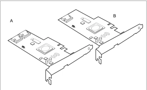
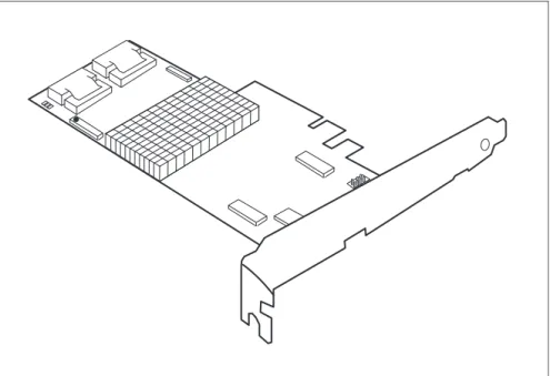
The RAID controller "RAID 0/1 SAS based on LSI MegaRAID" is designed to drive the server's internal disk drive. The RAID stack is based on LSI
MegaRAID® and offers powerful data throughput, extensive fault-tolerance and easy-to-use management.
Figure 2: "RAID 0/1 SAS based on LSI MegaRAID" controllers 1068 (A) and 1064 (B)
2.1.1
Features
● 3.3 V PCIe add-in card ● 4 / 8-Port SAS / SATA
● PCIe Interface x4 electrical, x8 mechanical ● One / two Mini 4x SFF-8087 Multilane Connectors
● 3.0 Gbit/s and 1.5 Gbit/s link rates for both SAS and SATA ● Integrated RAID (RAID 0, RAID 1, RAID 1E)
● Supports SSP, SMP, STB, and SATA Protocols ● Support of the following SATA II features:
– 3 Gbit/s SATA – Staggered Spin-Up – Hot Plug
– Native Command Queuing (NCQ)
● Comes without, with standard, with low-profile bracket.
2.1.2
Controller versions
Name Chip No. of SAS channels
Bracket type
S26361-D2507-B1x/D1x LSISAS1064e 4 low profile full height S26361-D2507-A1x/C1x LSISAS1068e 8 low profile full height
2.1.3
Connectors
The following figure shows the location of the connectors on the controllers.
1 HDD LED connector 2 SAS cable connector(s)
Connector Type Description
SAS MLC1 x4 SAS, ports 0 - 3 SFF 8087 Mini SAS connector for SAS IO cable to backplane and hard drives SAS MLC2 x4 SAS, ports 4 - 7 SFF 8087 Mini SAS connector for SAS IO
cable to backplane and hard drives HDD LED Hard drive activity
indication LED
8-pin connector
Pin 6 to connect activity LED
2
1 2
Figure 3: HDD LED connector
2.1.4
Installation
This section describes how to install the SAS RAID controller in a server.
V
CAUTION!To safeguard against data loss, remember to back up your data before you change your system configuration.
To install the new controller, proceed as follows:
Step 1 Unpack the controller
Unpack the new controller in a static-free environment. Remove it from the anti-static bag and inspect it for damage.
If the controller appears to be damaged, contact the Fujitsu support service.
Step 2 Prepare the server
Turn off the server and remove the cover from the chassis.
1
2 4
3
6
5
8
7
Step 3 Install the new SAS RAID controller
Insert the controller in a suitable PCI Express slot on the mainboard, as shown in the figure above (see your mainboard guide for information on the PCI Express slot). Press down gently but firmly to ensure the card is properly seated in the slot. Secure the controller to the computer chassis with the PCI card hold down latches. Connect the SAS and/or SATA HDDs located in the system to the SAS cable connector(s) on the controller.
Step 4 Power-up the computer
Replace the computer cover and reconnect the power cable(s). Start up the computer. Ensure that the SAS and/or SATA II devices are powered up before or at the same time as the host computer. If the host computer is powered up before the SAS or SATA II devices, the devices might not be recognized.
Step 5 Run the LSI Logic Configuration Utility
Run the LSI Logic Configuration Utility to configure the physical arrays and logical drives.
Press CTRL+C immediately to run the utility, when the following message appears on the screen:
Press <Ctrl><C> to start LSI Logic Configuration Utility
Step 6 Install the operating system driver
The controller can operate under various operating systems. To use these operating systems, you must install software drivers. The ServerView Suite DVD 1 includes drivers for the supported operating systems, along with documentation. You can view the supported operating systems and download the latest drivers for RAID adapters on the website at: http://support.ts.fujitsu.com
For the Japanese market please use the URL:
2.2
RAID controller "RAID 5/6 SAS based on
LSI MegaRAID (D2516)"
V
ATTENTION!Make sure you observe the safety notes in section "Important notes" on page 7.
The RAID controller "RAID 5/6 SAS based on LSI MegaRAID" is designed to drive the server's internal disk drives. The RAID stack is based on LSI MegaRAID® and offers powerful data throughput, extensive fault-tolerance and easy-to-use management.
Figure 4: "RAID 5/6 SAS based on LSI MegaRAID" controller (1078)
2.2.1
Features
● Industry-proven MegaRAID® data protection ● Flexibility for both SAS and SATA II
● Optionally secured with BBU
● Offers advanced MegaRAID functionality to integrated LSI SAS
● 3.3 V PCIe add-in card ● 4-lane 2.5 Gbit PCIe host bus ● 8 SAS/SATA ports
● Each SAS/SATA port supports SSP, SMP and STP ● Support for the following STP features:
– Addressing of SATA targets through expander – Native Command Queuing (NCQ)
● Support of the following SSP features:
– Wide port functionality (2 or 4 Phys from a single quad port) – Narrow port functionality (1 Phy)
– Compatible with SATA target devices
● 2 Mini 4x SFF-8087 connectors
● Hot-plug drives
● SGPIO interfaces for signaling of SAS/SATA ports ● Hardware XOR for RAID parity calculations ● 72-bit wide 256 / 512 MB of DDR2 667 (with ECC)
2.2.2
Controller versions
Name Chip Cache No. of SAS channels Bracket type S26361-D2516-A1x/Cx LSISAS1078e 256 MB 8 without low profile full height S26361-D2516-B1x/Dx LSISAS1078e 512 MB 8 without low profile full height
2.2.3
Connectors and indicators
The following figure shows the location of the connectors and indicators on the SAS RAID controller.
Connectors
1 HDD LED connector 2 iBBU connector
3 LEDs 4 SAS cable connectors
5 RAID key holder
Connector Type Description
SAS MLC1 x4 SAS, ports 0 - 3 SFF 8087 Mini SAS connector for SAS IO cable to backplane and hard drives SAS MLC2 x4 SAS, ports 4 - 7 SFF 8087 Mini SAS connector for SAS IO
4
5
1
2
3
Figure 5: HDD LED connector
Indicators
2.2.4
Installation
This section describes how to install the SAS RAID controller in a server.
V
CAUTION!To safeguard against data loss, remember to back up your data before you change your system configuration.
To install the new controller, proceed as follows: HDD LED Hard drive activity
indication LED
8-pin connector
Pin 6 to connect activity LED
iBBU Connector to attach external iBBU
LED Description
L1 (AL) Replacement for audible warning L2 (CD) Write pending (data cached)
Table 2: LED description
Step 1 Unpack the controller
Unpack the new controller in a static-free environment. Remove it from the anti-static bag and inspect it for damage.
If the controller appears to be damaged, contact the Fujitsu support service.
Step 2 Prepare the server
Connector Type Description
1
2 4
3
6
5
8
7
Step 3 Install the new SAS RAID controller
Insert the controller in a suitable PCI Express slot on the main board, as shown in the figure above (see your main board guide for information on the PCI Express slot). Press down gently but firmly to ensure the card is properly seated in the slot. Secure the controller to the computer chassis with the PCI card hold down latches. Connect the SAS and/or SATA HDDs located in the system to the SAS cable connector(s) on the controller.
Step 4 Power-up the computer
Replace the computer cover and reconnect the power cable(s). Start up the computer. Ensure that the SAS and/or SATA II devices are properly connected to the controller.
During booting, a message similar to the following is displayed: LSI MegaRAID SAS-MFI BIOS Version NTxx (Build ..date..)
Copyright(c) 2007, LSI Logic Corporation HA-x (Bus x Dev y) RAID 5/6 SAS based on LSI MegaRAID
FW package: xxxx
Step 5 Run the WebBIOS Configuration Utility
Run the WebBIOS Configuration Utility to configure the physical arrays and logical drives. Press CTRL+H immediately to run the utility, when the following message appears on the screen:
Press <Ctrl><H> for WebBIOS
Step 6 Install the operating system driver
The controller can operate under various operating systems. To use these operating systems, you must install software drivers.The ServerView Suite DVD 1 includes drivers for the supported operating systems, along with documentation. You can view the supported operating systems and download the latest drivers for RAID adapters on the website at:
http://support.ts.fujitsu.com
For the Japanese market please use the URL:
2.2.5
Installing an optional iBBU module
2.2.5.1 Features
The MegaRAID LSliBBU01/LSliBBU07 is an innovative, industry-exclusive module and offers intelligent monitoring capabilities, accessible via ServerView RAID.
The capabilities of the LSliBBU01/LSliBBU07 include monitoring the battery status and power levels as well as the ability to recondition and calibrate the battery for improved reliability. It maintains data in the cache in the case of powerfail (see data sheet for hold time duration).
2.2.5.2 Installation
The LSliBBU01/LSliBBU07 supports remote connection to the Modular RAID Controller "RAID 5/6 SAS based on LSI MegaRAID".
The LSliBBU01/LSliBBU07 is not installed directly on the RAID controller. Instead, use one of the supplied cables to connect the LSliBBU01/LSliBBU07 to the RAID controller. The battery backup unit must be mounted inside the chassis.
I
Because server chassis vary, there is no standard mounting option that is compatible with all the different system configurations. Refer to your server’s Options Guide or Upgrade and Maintenance Manual for mounting details.Therefore, the LSliBBU01/LSliBBU07 battery kit contains only the battery and a set of cables, allowing you to customize the location of the remote battery to provide the most flexibility within different
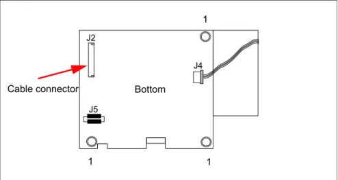
Figure 6: Position of the cable connector LSliBBU01
Figure 7: Position of the cable connector LSIiBBU07
Note the cable connector marked with the red arrow and the holes (1) for the screws that attach the LSliBBU01/LSliBBU07 to the chassis.
Cable connector Bottom 1 1 1 1 1 1 J2 J5 J4 Cable connector Bottom
1 1
To install the LSliBBU01/LSliBBU07 remotely to the RAID controller, proceed as follows:
1. Ground yourself, then remove the LSliBBU01/LSliBBU07 from its package. 2. Secure the LSliBBU01/LSliBBU07 to the server chassis as described in the
server documentation.
3. Insert the battery pack harness connector (at the end of the colored wires) into the J2 connector (LSliBBU01, see figure 6) or J4 connector (LSliBBU07, see figure 7) on the bottom of the iBBU.
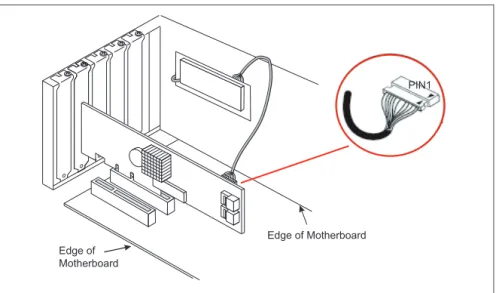
4. Connect the cable from the cable connector (for LSliBBU01 see figure 6 or for LSliBBU07 see figure 7) on the iBBU to the BBU connector on the RAID controller.
I
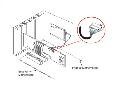
The connectors are marked with a black dot to indicate pin 1.Figure 8: Example: Installing the iBBU01 in a server chassis
PIN1
Edge of Motherboard Edge of
3.1
RAID controller "RAID Ctrl SAS 6G 0/1
(D2607)"
V
ATTENTION!Make sure you observe the safety notes in section "Important notes" on page 7.
The RAID controller "RAID 0/1 SAS based on LSI MegaRAID" is designed to drive the server's internal disk drive. The RAID stack is based on LSI
MegaRAID® and offers powerful data throughput, extensive fault-tolerance and easy-to-use management.
3.1.1
Features
● 3.3 V / 12 V PCIe add-in card ● 8 lanes wide 5 Gbit/s PCIe host bus ● 8 SAS / SATA ports
● each SAS / SATA port supports SSP, SMP, STP, and SATA protocols ● support of the following STP features:
– Addressing of SATA targets thru expander – Native Command Queuing (NCQ)
● support of the following SSP features:
– Wide port functionality (2, 3 or 4 Phys from a single quad port) – Narrow port functionality (1 Phy)
– Compatible with SATA target devices
● 2 Mini SAS 4i SFF-8087 multilane connectors ● Drive spin-up sequencing control
● Hot plug drives
● 1.5 Gbit/s, 3.0 Gbit/s and 6.0 GB/s link rates for both SAS and SATA ● Supported RAID levels: RAID 0, 1, 1E, 10
● 2 SGPIO interfaces for signaling of the 2 sets of quad SAS/SATA ports ● RAID-key chip onboard
3.1.2
Controller versions
3.1.3
Connectors and indicators
The following figure shows the location of the connectors and indicators on the SAS RAID controller.
Name Chip No. of SAS
channels Bracket type
S26361-D2607-Ax LSI SAS2008 8 low profile full height
1 HDD LED connector 3 SAS cable connectors
2 LEDs
1
2
Connectors
Figure 10: HDD LED connector
Indicators
3.1.4
Installation
This section describes how to install the SAS RAID controller in a server.
V
CAUTION!To safeguard against data loss, remember to back up your data before you change your system configuration.
To install the new controller, proceed as follows:
Connector Type Description
SAS MLC1 x4 SAS, ports 0 - 3 SFF Mini SAS connector for SAS IO cable to backplane and hard drives
SAS MLC2 x4 SAS, ports 4 - 7 SFF 8087 Mini SAS connector for SAS IO cable to backplane and hard drives HDD LED Hard drive activity
indication LED
8-pin connector
Pin 6 to connect activity LED
LED Description
L1 (HB) Heart Beat L2 (ERR) Error
Step 1 Unpack the controller
Unpack the new controller in a static-free environment. Remove it from the anti-static bag and inspect it for damage.
1
2 4
3
6
5
8
7
Step 2 Prepare the server
Turn off the server and remove the cover from the chassis.
Step 3 Install the new SAS RAID controller
Insert the controller in a suitable PCI Express slot on the mainboard, as shown in the figure above (see your mainboard guide for information on the PCI Express slot). Press down gently but firmly to ensure the card is properly seated in the slot. Secure the controller to the computer chassis with the PCI card hold down latches. Connect the SAS and/or SATA HDDs located in the system to the SAS cable connector(s) on the controller.
Edge of Motherboard Edge of
Motherboard
Press Here Press Here
Step 4 Power-up the computer
Replace the computer cover and reconnect the power cable(s). Start up the computer. Ensure that the SAS and/or SATA II devices are powered up before or at the same time as the host computer. If the host computer is powered up before the SAS or SATA II devices, the devices might not be recognized.
During booting, a message similar to the following is displayed: LSI MegaRAID SAS-MFI BIOS
Version NTxx (Build..date..) Copyright(c) 2010 LSI Corporation
HA-x (Bus x Dev y) RAID Ctrl SAS 6G 0/1 (D2607)) FW package: xxxx
Step 5 Run the LSI Logic Configuration Utility
Run the LSI Logic Configuration Utility to configure the physical arrays and logical drives.
Press CTRL+H immediately to run the utility, when the following message appears on the screen:
Press <Ctrl><H> to start LSI Logic Configuration Utility
Step 6 Install the operating system driver
The controller can operate under various operating systems. To use these operating systems, you must install software drivers. The ServerView Suite DVD 1 includes drivers for the supported operating systems, along with documentation. You can view the supported operating systems and download the latest drivers for RAID adapters on the website at:
http://ts.fujitsu.com/support/
For the Japanese market please use the URL:
3.2
RAID Controller "RAID Ctrl SAS 6G 5/6
512 MB (D2616)"
V
ATTENTION!Make sure you observe the safety notes in section "Important notes" on page 7.
The RAID controller "RAID 5/6 SAS based on LSI MegaRAID" is designed to drive the server's internal disk drives. The RAID stack is based on LSI MegaRAID® and offers powerful data throughput, extensive fault-tolerance and easy-to-use management.
3.2.1
Features
● Industry-proven MegaRAID® data protection ● Flexibility for both SAS 2.0 and SATA II
● Advanced management and configuration suites ● Supports RAID levels 0, 1, 1E, 5, 6, 10, 50 and 60 ● Optionally secured with BBU
● Offers advanced MegaRAID functionality to integrated LSI SAS
● 3.3 V / 12 V PCIe add-in card ● 8-lane 5.0 Gbit PCIe host bus ● 8 SAS/SATA ports
● Each SAS/SATA port supports SSP, SMP and STP ● Support for the following STP features:
– Addressing of SATA targets through expander – Native Command Queuing (NCQ)
● Support of the following SSP features:
– Wide port functionality (2 or 4 Phys from a single quad port) – Narrow port functionality (1 Phy)
– Compatible with SATA target devices
● 2 Mini SAS 4i SFF-8087 connectors ● Hot-plug drives
● SGPIO interfaces for signaling of SAS/SATA ports ● Hardware XOR for RAID parity calculations ● 72-bit wide 512 MB of DDR2 800 (with ECC)
3.2.2
Controller versions
3.2.3
Connectors and indicators
The following figure shows the location of the connectors and indicators on the SAS RAID controller.
Name Chip Cache No. of SAS channels
Bracket type
S26361-D2616-Ax LSI SAS2108 512 MB 8 low profile full height
1 iBBU connector 3 SAS cable connectors
2 LEDs 4 HDD LED connector
1
2
3
Connectors
Figure 12: HDD LED connector
Indicators
Connector Type Description
SAS MLC1 x4 SAS, ports 0 - 3 SFF 8087 Mini SAS connector for SAS IO cable to backplane and hard drives SAS MLC2 x4 SAS, ports 4 - 7 SFF 8087 Mini SAS connector for SAS IO
cable to backplane and hard drives HDD LED Hard drive activity
indication LED
8-pin connector
Pin 6 to connect activity LED iBBU 1-20 Connector to attach remote iBBU
LED Description
L1 (HB) Heart Beat
L2 (WP) Write in cache pending L3 (WA) Warning
1
2 4
3
6
5
8
7
3.2.4
Installation
This section describes how to install the SAS RAID controller in a server.
V
CAUTION!To safeguard against data loss, remember to back up your data before you change your system configuration.
To install the new controller, proceed as follows:
Step 1 Unpack the controller
Unpack the new controller in a static-free environment. Remove it from the anti-static bag and inspect it for damage.
If the controller appears to be damaged, contact the Fujitsu support service.
Step 2 Prepare the server
Step 3 Install the new SAS RAID controller
Insert the controller in a suitable PCI Express slot on the mainboard, as shown in the figure above (see your mainboard guide for information on the PCI Express slot). Press down gently but firmly to ensure the card is properly seated in the slot. Secure the controller to the computer chassis with the PCI card hold down latches. Connect the SAS and/or SATA HDDs located in the system to the SAS cable connector(s) on the controller.
Edge of Motherboard Edge of
Motherboard
Press Here Press Here
Step 4 Power-up the computer
Replace the computer cover and reconnect the power cable(s). Start up the computer. Ensure that the SAS and/or SATA II devices are properly connected to the controller.
During booting, a message similar to the following is displayed: LSI MegaRAID SAS-MFI BIOS Version NTxx (Build ..date..)
Copyright(c) 2009, LSI Logic Corporation HA-x (Bus x Dev y) RAID Ctrl SAS 6G 5/6 512MB (D2616)
FW package: xxxx
Step 5 Run the WebBIOS Configuration Utility
Run the WebBIOS Configuration Utility to configure the physical arrays and logical drives. Press CTRL+H immediately to run the utility, when the following message appears on the screen:
Press <Ctrl><H> for WebBIOS
Step 6 Install the operating system driver
The controller can operate under various operating systems. To use these operating systems, you must install software drivers.The ServerView Suite DVD 1 includes drivers for the supported operating systems, along with documentation. You can view the supported operating systems and download the latest drivers for RAID adapters on the website at:
http://ts.fujitsu.com/support/
For the Japanese market please use the URL:
3.2.5
Installing an optional iBBU module
3.2.5.1 Features
The MegaRAID LSIiBBU07 / LSIiBBU08 is an innovative, industry-exclusive module and offers intelligent monitoring capabilities, accessible via ServerView RAID.
The capabilities of the LSIiBBU07 / LSIiBBU08 include monitoring the battery status and power levels as well as the ability to recondition and calibrate the battery for improved reliability. It maintains data in the cache in the case of powerfail (see data sheet for hold time duration).
3.2.5.2 Installation
The LSIiBBU07 / LSIiBBU08 supports remote connection to the Modular RAID Controller "RAID Ctrl SAS 6G 5/6 512 MB (D2616)".
The LSIiBBU07 / LSIiBBU08 is not installed directly on the RAID controller. Instead, use one of the supplied cables to connect the LSIiBBU07 / LSIiBBU08 to the RAID controller. The battery backup unit must be mounted inside the chassis.
I
Because server chassis vary, there is no standard mounting option that is compatible with all the different system configurations. Refer to your server’s Options Guide or Upgrade and Maintenance Manual for mounting details.Therefore, the LSIiBBU07 / LSIiBBU08 battery kit contains only the battery and a set of cables, allowing you to customize the location of the remote battery to provide the most flexibility within different
Figure 13: Position of the cable connector LSIiBBU07 / LSIiBBU08
Note the cable connector marked with the red arrow and the holes (1) for the screws that attach the LSIiBBU07 / LSIiBBU08 to the chassis.
To install the LSIiBBU07 / LSIiBBU08 remotely to the RAID controller, proceed as follows:
1. Ground yourself, then remove the LSIiBBU07 / LSIiBBU08 from its package. 2. Secure the LSIiBBU07 / LSIiBBU08 to the server chassis as described in
the server documentation.
3. Insert the battery pack harness connector (at the end of the colored wires) into the J4 connector (see figure 13) on the bottom of the
LSIiBBU07 / LSIiBBU08.
4. Connect the cable from the cable connector (see figure 13) on the LSIiBBU07 / LSIiBBU08 to the BBU connector on the RAID controller.
I
The connectors are marked with a black dot to indicate pin 1. J2J5
J4 Cable connector Bottom
1 1
Figure 14: Installing the iBBU07 / iBBU08 in a server chassis
PIN1
Edge of Motherboard Edge of
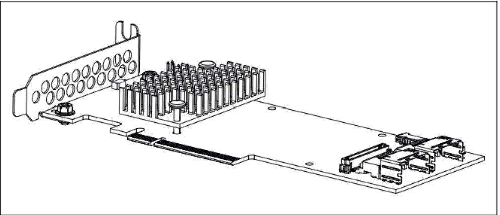
3.3
RAID Controller "PY SAS RAID Mezz Card
6 Gb (D3016)"
V
ATTENTION!Make sure you observe the safety notes in section "Important notes" on page 7.
The RAID controller "PY SAS RAID Mezz Card 6 Gb (D3016)" is designed to drive the BX400 and BX900 server's internal or external disk drives. The RAID stack is based on LSI MegaRAID® and offers powerful data throughput, extensive fault-tolerance and easy-to-use management.
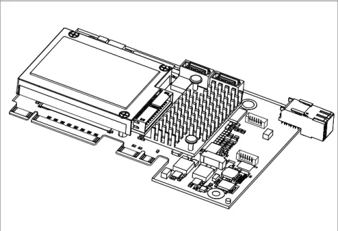
Figure 15: "PY SAS RAID Mezz Card 6 Gb (D3016)" with optional iBBU (based on LSI SAS2108)
3.3.1
Features
● Industry-proven MegaRAID® data protection ● Flexibility for both SAS 2.0 and SATA II
● Advanced management and configuration suites ● Supports RAID levels 0, 1, 1E, 5, 6, 10, 50 and 60 ● Optionally secured with BBU
● Offers advanced MegaRAID functionality to integrated LSI SAS
● 12 V PCIe add-in card ● 8-lane 5.0 Gbit PCIe host bus ● 8 SAS/SATA ports
● Each SAS/SATA port supports SSP, SMP and STP ● Support for the following STP features:
– Addressing of SATA targets through expander – Native Command Queuing (NCQ)
● Support of the following SSP features:
– Wide port functionality (2 or 4 Phys from a single quad port) – Narrow port functionality (1 Phy)
– Compatible with SATA target devices
● 2 x SATA connectors for internal hard disk drives, 1 x SAS lane each
● 1 x Midplane connector, 4 x SAS lanes ● Hot-plug drives
● SGPIO interfaces for signaling of SAS/SATA ports ● Hardware XOR for RAID parity calculations ● 72-bit wide 512 MB of DDR2 800 (with ECC)
3.3.2
Controller versions
3.3.3
Connectors and indicators
The following figure shows the location of the connectors and indicators on the SAS RAID controller.
1 iBBU 4 LED
2 SAS cable connectors 5 iBBU connector 3 SDB connector 1 2 3 4 5
Connectors
Indicators
3.3.4
Installation
This section describes how to install the SAS RAID controller in a server.
V
CAUTION!To safeguard against data loss, remember to back up your data before you change your system configuration.
To install the new controller, proceed as follows:
Connector Type Description
SAS0 x1 SAS0 SATA connectors to connect local SAS/SATA hard disk drives SAS1 x1 SAS1 SATA connectors to connect local
SAS/SATA hard disk drives SDB SAS side band
signals
6-pin connector
SAS side band connector
BBU Connector for direct iBBU connection
LED Description
HB Heart Beat
WP Write in cache pending
WA Warning
Step 1 Unpack the controller
Unpack the new controller in a static-free environment. Remove it from the anti-static bag and inspect it for damage.
If the controller appears to be damaged, contact the Fujitsu support service.
Step 2 Prepare the server
Step 3 Install the new SAS RAID controller
Refer to the server blade specific Options Guide or Upgrade and Maintenance Manual.
Step 4 Power-up the server
Replace the server cover and reinstall the server blade to the chassis. Start up the computer. Ensure that the SAS and/or SATA II devices are properly connected to the controller. During booting, a message similar to the following is displayed: LSI MegaRAID SAS-MFI BIOS Version NTxx (Build ..date..)
Copyright(c) 2010, LSI Logic Corporation HA-x (Bus x Dev y) PY SAS RAID Mezz Card 6GB (D3016)
FW package: xxxx
Step 5 Run the WebBIOS Configuration Utility
Run the WebBIOS Configuration Utility to configure the physical arrays and logical drives. Press CTRL+H immediately to run the utility, when the following message appears on the screen:
Press <Ctrl><H> for WebBIOS
Step 6 Install the operating system driver
The controller can operate under various operating systems. To use these operating systems, you must install software drivers.The ServerView Suite DVD 1 includes drivers for the supported operating systems, along with documentation. You can view the supported operating systems and download the latest drivers for RAID adapters on the website at:
http://ts.fujitsu.com/support/
For the Japanese market please use the URL:
3.3.5
Installing an optional iBBU module
3.3.5.1 Features
The MegaRAID LSIiBBU08 is an innovative, industry-exclusive module and offers intelligent monitoring capabilities, accessible via ServerView RAID Manager.
The capabilities of the LSIiBBU08 include monitoring the battery status and power levels as well as the ability to recondition and calibrate the battery for improved reliability. It maintains data in the cache in the case of powerfail (see data sheet for hold time duration).
3.3.5.2 Installation
The LSIiBBU08 supports board to board connection to the modular RAID controller "PY SAS RAID Mezz Card 6 Gb (D3016)".
Note the board to board connector (1) and the holes (2) for the screws that attach the LSIiBBU08 to the RAID Mezz Card.
To install the LSIiBBU08 to the RAID controller, proceed as follows: 1. Ground yourself, then remove the LSIiBBU08 from its package.
2. Align iBBU08 connector J1 with iBBU connector of RAID Mezz Card and fix the iBBU08 as described in the server documentation.
1 2
2
3.4
RAID Controller "RAID Ctrl SAS 6G 1GB
(D3116)"
V
ATTENTION!Make sure you observe the safety notes in section "Important notes" on page 7.
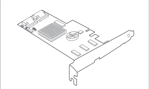
The RAID controller "RAID Ctrl SAS 6G 1GB (D3116)" is designed to drive the server's internal disk drives. The RAID stack is based on LSI MegaRAID® and offers powerful data throughput, extensive fault-tolerance and easy-to-use management.
Figure 16: "RAID Ctrl SAS 6G 1GB (D3116)" controller (based on LSI SAS2208)
I
Depending on the target system, the following bracket types are offered: – Full height perforated– Full height not perforated – Low profile perforated
3.4.1
Features
● Industry-proven MegaRAID® data protection ● Flexibility for both SAS 2.0 and SATA II / SATA III ● Advanced management and configuration suites ● Supports RAID levels 0, 1, 1E, 5, 6, 10, 50 and 60 ● Optional RAID controller cache backup unit
● Offers advanced MegaRAID functionality to integrated LSI SAS
● 3.3 V / 12 V PCIe add-in card ● 8-lane 5.0 / 8.0 Gbit PCIe host bus ● 8 SAS/SATA ports
● Each SAS/SATA port supports SSP, SMP and STP ● Support for the following STP features:
– Addressing of SATA targets through expander – Native Command Queuing (NCQ)
● Support of the following SSP features:
– Wide port functionality (2 or 4 Phys from a single quad port, or or 8 Phys over two quad ports)
– Narrow port functionality (1 Phy) – Compatible with SATA target devices
● 2 Mini SAS 4i SFF-8087 connectors ● Hot-plug drives
● SGPIO interfaces for signaling of SAS/SATA ports ● Hardware XOR for RAID parity calculations
3.4.2
Controller versions
3.4.3
Connectors and indicators
The following figure shows the location of the connectors and indicators on the SAS RAID controller.
Name Chip PCIe Cache No. of SAS channels
Bracket type
S26361-D3116-Bx LSI SAS2208 PCIe 2.0 1 GB 8
low profile full height
S26361-D3116-Cx LSI SAS2208 PCIe 3.0 1 GB 8
low profile full height
1 HDD LED connector 4 FBU connector on TFM 2 TFM indicator LEDs 5 Indicator LEDs
Connectors
RAID controller indicators
TFM indicators
Connector Type Description
SAS MLC1 x4 SAS, ports 0 - 3 SFF 8087 Mini SAS connector for SAS IO cable to backplane and hard drives SAS MLC2 x4 SAS, ports 4 - 7 SFF 8087 Mini SAS connector for SAS IO
cable to backplane and hard drives HDD LED Hard drive activity
indication LED
6-pin connector
Pin 4 to connect activity LED
FBU 1-6 Connector on TFM to attach FBU
LED Description
L1 (HB) Heart Beat
L2 (SE0) Error for Power PC0 L3 (SE1) Error for Power PC1
LED Description
L1 (green) Power available L2 (blue) TFM / FBU status L3 (yellow) Cache offload fault
3.4.4
Installation
This section describes how to install the SAS RAID controller in a server.
V
CAUTION!To safeguard against data loss, remember to back up your data before you change your system configuration.
To install the new controller, proceed as follows:
Step 1 Unpack the controller
Unpack the new controller in a static-free environment. Remove it from the anti-static bag and inspect it for damage.
If the controller appears to be damaged, contact the Fujitsu support service.
Step 2 Prepare the server
Turn off the server and remove the cover from the chassis.
Step 3 Install the new SAS RAID controller
Insert the controller in a suitable PCI Express slot on the system board. Press down gently but firmly to ensure the controller is properly seated in the slot. Secure the controller to the computer chassis with the PCI card hold down latches. Connect the SAS and/or SATA HDDs located in the system to the SAS cable connector(s) on the controller. Refer to your server specific Upgrade and Maintenance Manual for information on the PCI Express slot and installing the controller.
Step 4 Power-up the computer
Replace the computer cover and reconnect the power cable(s). Start up the computer. Ensure that the SAS and/or SATA II devices are properly connected to the controller.
During booting, a message similar to the following is displayed: LSI MegaRAID SAS-MFI BIOS Version NTxx (Build ..date..)
Copyright(c) 2009, LSI Logic Corporation
HA-x (Bus x Dev y) RAID Ctrl SAS 6G 1GB (D3116) FW package: xxxx
Step 5 Run the WebBIOS Configuration Utility
Run the WebBIOS Configuration Utility to configure the physical arrays and logical drives. Press CTRL+H immediately to run the utility, when the following message appears on the screen: Press <Ctrl><H> for WebBIOS
Step 6 Install the operating system driver
The controller can operate under various operating systems. To use these operating systems, you must install software drivers.The ServerView Suite DVD 1 includes drivers for the supported operating systems, along with documentation. You can view the supported operating systems and download the latest drivers for RAID adapters on the website at:
http://ts.fujitsu.com/support/
For the Japanese market please use the URL:
3.4.5
Installing an optional TFM / FBU module
3.4.5.1 Features
Using the LSI MegaRAID® CacheVault™ Technology offers better protection for controller cache with our eco-friendly, low-maintenance 6Gb/s LSI MegaRAID based controllers featuring CacheVault Technology.
This technology offloads data stored in the LSI MegaRAID based controller cache to the NAND flash in the event of a power failure or other system occurrence where the contents of controller cache are most at risk.
In addition, CacheVault technology eliminates the need for lithium ion (Li-ion) batteries, traditionally used to protect DRAM cache memory on PCI RAID controllers.
CacheVault technology offers:
CacheVault technology transfers the contents of the DRAM cache to NAND flash using power from the supercap module in the event of a power or server failure. With a traditional battery backup unit, after a limited time without restored power, the cached data is lost. However, CacheVault technology safely stores the contents of DRAM on NAND flash for up to three years.
3.4.5.2 Installation
The FBU supports remote connection to the Modular RAID Controller "RAID Ctrl SAS 6G 1GB (D3116)".
The FBU is not installed directly on the RAID controller. Instead, use one of the supplied cables to connect the FBU to the TFM on the RAID controller. The cache backup unit must be mounted inside the chassis.
I
Because server chassis vary, there is no standard mounting option that is compatible with all the different system configurations. Refer to your server’s Options Guide or Upgrade and Maintenance Manual for mounting details.Therefore, the FBU kit contains only the cache unit and a set of cables, allowing you to customize the location of the remote cache backup unit to provide the most flexibility within different environments.
I
For mounting the TFM, remove the controller from your system. When removing / connecting the FBU from / to the TFM, remove AC power from your system.To install the TFM and FBU, proceed as follows:
Figure 17: Installing the TFM
Ê Ground yourself, then fit the spacer bolts on the TFM on SAS RAID controller (1).
Ê Secure the TFM on the controller with the three screws from the TFM kit (2). Ê Remove the FBU from its package.
Figure 18: Installing the FBU in the FBU holder
Ê At a slight angle, fit the FBU under both retaining brackets of the FBU holder as shown (1). Push in the FBU until it locks in place (2).
Figure 19: Connecting the FBU adapter cable to the FBU
Ê Connect the cable end of the FBU cable to the FBU adapter cable as shown. Ê Secure the FBU to the server chassis as described in the server
3.5
RAID Controller "PY SAS RAID HDD Module
(D2816)"
V
ATTENTION!Make sure you observe the safety notes in section "Important notes" on page 7.
The RAID controller "PY SAS RAID HDD Module (D2816)" is designed to drive the BX920 server's internal or BX400 / BX900 external disk drives. The RAID stack is based on LSI MegaRAID® and offers powerful data throughput, extensive fault-tolerance and easy-to-use management.
3.5.1
Features
● Industry-proven MegaRAID® data protection ● Flexibility for both SAS 2.0 and SATA II / SATA III ● Advanced management and configuration suites ● 12V PCIe RAID HDD module
● Supports RAID levels 0, 1, 1E, 5, 6, 10, 50 and 60 ● Optional RAID controller cache backup unit
● Offers advanced MegaRAID functionality to integrated LSI SAS ● 8-lane 5.0 / 8.0 Gbit PCIe host bus
● 6 SAS/SATA ports, (2+2 ports for Storage Blade Connection and 2 ports for
Blade internal HDD Connection)
● Each SAS/SATA port supports SSP, SMP and STP ● Support for the following STP features:
– Addressing of SATA targets through expander – Native Command Queuing (NCQ)
● Support of the following SSP features:
– Wide port functionality (2x2 Phys from a single quad port) – Narrow port functionality (1 Phy)
– Compatible with SATA target devices
● Hot-plug drives
● SGPIO interfaces for signaling of SAS/SATA ports ● Hardware XOR for RAID parity calculations
3.5.2
Controller versions
3.5.3
Connectors and indicators
The following figure shows the location of the connectors and indicators on the SAS RAID controller.
Name Chip PCIe Cache No. of SAS channels
S26361-D2816-Ax LSI SAS2208 PCIe 2.0 512 MB
2+2 ports for Storage Blade Connection 2 ports for Blade internal HDD Connection
S26361-D2816-Cx LSI SAS2208 PCIe 3.0 512 MB
2+2 ports for Storage Blade Connection 2 ports for Blade internal HDD Connection
Connectors
Indicators
3.5.4
Installation
This section describes how to install the SAS RAID controller in a server.
V
CAUTION!To safeguard against data loss, remember to back up your data before you change your system configuration.
To install the new controller, proceed as follows:
Connector Type Description
FBU 1-6 Connector to attach FBU
LED Description
L1 (H322) Heart Beat
L2 (H321) Error for Power PC1 L3 (H320) Error for Power PC0 L4 (H102) Power available L5 (H101) Status
L6 (H100) Cache offload fault
Step 1 Unpack the controller
Unpack the new controller in a static-free environment. Remove it from the anti-static bag and inspect it for damage.
If the controller appears to be damaged, contact the Fujitsu support service.
Step 2 Prepare the server
Shut down and power off the server and remove the server blade from the chassis.
Step 4 Power-up the server
Replace the server cover and reinstall the server blade to the chassis. Start up the computer. Ensure that the SAS and/or SATA II devices are properly connected to the controller. During booting, a message similar to the following is displayed: LSI MegaRAID SAS-MFI BIOS Version NTxx (Build ..date..)
Copyright(c) 2010, LSI Logic Corporation
HA-x (Bus x Dev y) PY SAS RAID HDD Module (D2816) FW package: xxxx
Step 5 Run the WebBIOS Configuration Utility
Run the WebBIOS Configuration Utility to configure the physical arrays and logical drives. Press CTRL+H immediately to run the utility, when the following message appears on the screen: Press <Ctrl><H> for WebBIOS
Step 6 Install the operating system driver
The controller can operate under various operating systems. To use these operating systems, you must install software
drivers.The ServerView Suite DVD 1 includes drivers for the supported operating systems, along with documentation. You can view the supported operating systems and download the latest drivers for RAID adapters on the website at:
http://ts.fujitsu.com/support/
For the Japanese market please use the URL:
3.5.5
Installing an optional FBU module
3.5.5.1 Features
Using the LSI MegaRAID® CacheVault™ Technology offers better protection for controller cache with our eco-friendly, low-maintenance 6Gb/s LSI MegaRAID based controllers featuring CacheVault Technology.
This technology offloads data stored in the LSI MegaRAID based controller cache to the NAND flash in the event of a power failure or other system occurrence where the contents of controller cache are most at risk.
In addition, CacheVault technology eliminates the need for lithium ion (Li-ion) batteries, traditionally used to protect DRAM cache memory on PCI RAID controllers.
CacheVault technology offers:
CacheVault technology transfers the contents of the DRAM cache to NAND flash using power from the supercap module in the event of a power or server failure. With a traditional battery backup unit, after a limited time without restored power, the cached data is lost. However, CacheVault technology safely stores the contents of DRAM on NAND flash for up to three years.
3.5.5.2 Installation
The FBU supports remote connection to the Modular RAID Controller "PY SAS RAID HDD Module (D2816)". The FBU is directly connected to the RAID controller.
I
Because server chassis vary, there is no standard mounting option that is compatible with all the different system configurations. Refer to your server’s Options Guide or Upgrade and Maintenance Manual for mounting details.To install the FBU to the RAID controller, proceed as follows: Ê Ground yourself.
Figure 21: LSI FBU02A module
Ê Install the FBU into the system and connect it to the SAS RAID controller as described in the "PRIMERGY BX920 S3 Server Blade" Upgrade and Maintenance Manual.
3.6
SAS Controller "PY SAS RAID HDD Module
w/o Cache (D2837)"
V
ATTENTION!Make sure you observe the safety notes in section "Important notes" on page 7.
The RAID controller "PY SAS RAID HDD Module w/o Cache (D2837)" is designed to drive the BX400 and BX900 server's internal disk drives. The RAID stack is based on LSI MegaRAID® and offers powerful data throughput, extensive fault-tolerance and easy-to-use management.
3.6.1
Features
● Flexibility for both SAS 2.0 and SATA II / SATA III ● Advanced management and configuration suites ● 12V PCIe RAID HDD module
● Supports RAID levels 0, 1, 1E, 10
● Offers advanced MegaRAID functionality to integrated LSI SAS ● 8-lane 5.0 / 8.0 Gbit PCIe host bus
● 6 SAS/SATA ports, (2+2 ports for Storage Blade Connection and 2 ports for
Blade internal HDD Connection)
● Each SAS/SATA port supports SSP and STP ● Support for the following STP features:
– Addressing of SATA targets through expander – Native Command Queuing (NCQ)
● Support of the following SSP features:
– Wide port functionality (2x2 Phys from a single quad port) – Narrow port functionality (1 Phy)
– Compatible with SATA target devices
● SGPIO interfaces for signaling of SAS/SATA ports ● Drive spin-up sequencing control
● Hot-plug drives
● 1.5 Gbit/s, 3.0 Gbit/s and 6.0 Gbit/s link rates for both SAS an SATA
3.6.2
Controller versions
Name Chip PCIe No. of SAS channels
3.6.3
Connectors and indicators
The following figure shows the location of the connectors and indicators on the SAS controller.
Indicators
1 Indicators
LED Description
L1 (H322) Heart Beat
L2 (H321) Error for Power PC1 L3 (H320) Error for Power PC0
3.6.4
Installation
This section describes how to install the SAS RAID controller in a server.
V
CAUTION!To safeguard against data loss, remember to back up your data before you change your system configuration.
To install the new controller, proceed as follows:
Step 1 Unpack the controller
Unpack the new controller in a static-free environment. Remove it from the anti-static bag and inspect it for damage.
If the controller appears to be damaged, contact the Fujitsu support service.
Step 2 Prepare the server
Shut down and power off the server and remove the server blade from the chassis.
Step 3 Install the new SAS RAID controller
Refer to the server blade specific Options Guide or Upgrade and Maintenance Manual.
Step 4 Power-up the server
Replace the server cover and reinstall the server blade to the chassis. Start up the computer. Ensure that the SAS and/or SATA II devices are properly connected to the controller. During booting, a message similar to the following is displayed: LSI MegaRAID SAS-MFI BIOS Version NTxx (Build ..date..)
Copyright(c) 2010, LSI Logic Corporation
HA-x (Bus x Dev y) PY SAS RAID HDD Module w/o Cache (D2837)
Step 5 Run the WebBIOS Configuration Utility
Run the WebBIOS Configuration Utility to configure the physical arrays and logical drives. Press CTRL+H immediately to run the utility, when the following message appears on the screen:
Press <Ctrl><H> for WebBIOS
Step 6 Install the operating system driver
The controller can operate under various operating systems. To use these operating systems, you must install software drivers.The ServerView Suite DVD 1 includes drivers for the supported operating systems, along with documentation. You can view the supported operating systems and download the latest drivers for RAID adapters on the website at:
http://ts.fujitsu.com/support/
For the Japanese market please use the URL:
4.1
RAID Controller "PRAID EP400i / EP420i"
V
ATTENTION!Make sure you observe the safety notes in section "Important notes" on page 7.
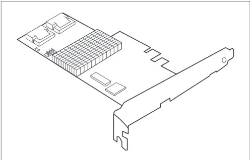
The RAID controller "PRAID EP400i / EP420i" (D3216) is designed to drive the server's internal disk drives. The RAID stack is based on LSI MegaRAID® and offers powerful data throughput, extensive fault-tolerance and easy-to-use management.
Figure 23: "PRAID EP400i / EP420i" (based on LSI SAS3108)
I
Depending on the target system, the following bracket types are offered: – Full height perforated4.1.1
Features
The RAID controller "PRAID EP400i / EP420i" implements the LSI SAS3108 which is an integrated SAS and I/O controller with dual embedded Power PC 476 cores running at speeds up to 1.2 GHz. The LSI SAS3108 also provides the following functionalities:
● Provides an 8-lane 5.0 / 8.0 Gbit PCIe 3.0 host bus.
● Provides an 8-port 12Gb/s SAS3 and 6Gb/s SATA3 interface.
● Provides a 1866-MHz DDR3 SDRAM interface with a hardware RAID assist
engine for parity calculations.
● Provides a full-featured hardware-based RAID solution that supports RAID
levels 0, 1, 1E, 5, 6, 10, 50, and 60.
● Six I2C interfaces used for Serial Boot strap ROM connection, memory
detection, PCI-E SMBus connectivity, battery / smart charger control, and SAS sideband control.
● Integrated dual UART for MegaRAID® diagnostic use only.
● Two banks of SGPIO signals to accompany the two sets of x4 SAS / SATA
ports.
● 16MB Flash
● 1kB Bootstrap EEPROM
● Mounting holes for TFM ● Raid-key chip onboard
4.1.2
Controller versions
Name Chip PCIe Cache No. of SAS channels Bracket type
PRAID EP400i S26361-D3216-Axx
LSI SAS3108 PCIe 3.0 1 GB 8 low profile full height PRAID EP420i
4.1.3
Connectors and indicators
The following figure shows the location of the connectors and indicators on the SAS RAID controller.
Figure 24: "PRAID EP400i / EP420i" board layout
1 SAS cable connectors 2 TFM (optional)
3 FBU connector on TFM 4 HDD LED connector 5 RAID controller indicator
Connectors
Indicators
4.1.4
Installation
This section describes how to install the SAS RAID controller in a server.
V
CAUTION!To safeguard against data loss, remember to back up your data before you change your system configuration.
To install the new controller, proceed as follows:
Connector Type Description
SAS MLC1 x4 SAS, ports 0- 3 SFF 8643 Mini SAS HD 4i connector for SAS IO cable to backplane and hard drives SAS MLC2 x4 SAS, ports 4- 7 SFF 8643 Mini SAS HD 4i connector for SAS
IO cable to backplane and hard drives HDD LED Hard drive activity
indication LED
6-pin connector
Pin 4 to connect activity LED FBU 1-6 Connector on TFM to attach FBU
LED Description
L1 (green blinking) Heart Beat
Step 1 Unpack the controller
Unpack the new controller in a static-free environment. Remove it from the anti-static bag and inspect it for damage.
If the controller appears to be damaged, contact the Fujitsu support service.
Step 2 Prepare the server