ARC-1680 Series
(PCIe to SAS RAID Controllers )
SAS RAID Cards
USER’S Manual
Version: 1.4
Copyright and Trademarks
The information of the products in this manual is subject to change without prior notice and does not represent a commitment on the part of the vendor, who assumes no liability or responsibility for any errors that may appear in this manual. All brands and trademarks are the properties of their respective owners. This manual contains materials protected under International Copyright Conventions. All rights
reserved. No part of this manual may be reproduced in any form or by any means, electronic or mechanical, including photocopying, without the written permission of the manufacturer and the author. All inquiries should be addressed to Areca Technology Corporation.
FCC STATEMENT
This equipment has been tested and found to comply with the lim-its for a Class B digital device, pursuant to part 15 of the FCC Rules. These limits are designed to provide reasonable protection against in-terference in a residential installation. This equipment generates, uses, and can radiate radio frequency energy and, if not installed and used in accordance with the instructions, may cause harmful interference to radio communications. However, there is no guarantee that interfer-ence will not occur in a particular installation.
Contents
1. Introduction ... 10
1.1 Overview ... 10
1.2 Features ... 12
2. Hardware Installation ... 16
2.1 Before Your Begin Installation ... 16
2.2 Board Layout ... 16
2.3 Installation ... 24
2.4 SAS Cables ... 31
2.4.1 Internal Min SAS 4i to SATA Cable ... 31
2.4.2 Internal Min SAS 4i to 4xSFF-8482 Cable ... 32
2.4.3 Internal Min SAS 4i to Internal Min SAS 4i cable ... 33
2.4.4 External Min SAS 4i Drive Boxes and Drive Expanders ... 33
2.5 LED Cables ... 34
2.6 Hot-plug Drive Replacement ... 39
2.6.1 Recognizing a Drive Failure ... 39
2.6.2 Replacing a Failed Drive ... 39
2.7 Summary of the installation ... 40
3. McBIOS RAID Manager ... 42
3.1 Starting the McBIOS RAID Manager ... 42
3.2 McBIOS RAID manager ... 43
3.3 Configuring Raid Sets and Volume Sets ... 44
3.4 Designating Drives as Hot Spares ... 44
3.5 Using Quick Volume /Raid Setup Configuration ... 45
3.6 Using RAID Set/Volume Set Function Method ... 46
3.7 Main Menu ... 48
3.7.1 Quick Volume/RAID Setup ... 49
3.7.2 Raid Set Function ... 53
3.7.2.1 Create Raid Set ... 54
3.7.2.2 Delete Raid Set ... 55
3.7.2.3 Expand Raid Set ... 56
• Migrating ... 57
3.7.2.4 Activate Incomplete Raid Set ... 57
3.7.2.5 Create Hot Spare ... 58
3.7.2.6 Delete Hot Spare ... 58
3.7.2.7 Raid Set Information ... 59
3.7.3 Volume Set Function ... 59
• Volume Name ... 62 • Raid Level ... 63 • Capacity ... 63 • Stripe Size ... 64 • SCSI Channel ... 65 • SCSI ID ... 65 • SCSI LUN ... 66 • Cache Mode ... 66 • Tag Queuing ... 67
3.7.3.2 Create Raid30/50/60 (Volume Set 30/50/60) ... 67
3.7.3.3 Delete Volume Set ... 68
3.7.3.4 Modify Volume Set ... 69
3.7.3.5 Check Volume Set ... 71
3.7.3.6 Stop Volume Set Check ... 72
3.7.3.7 Display Volume Set Info. ... 72
3.7.4 Physical Drives ... 72
3.7.4.1 View Drive Information ... 73
3.7.4.2 Create Pass-Through Disk ... 73
3.7.4.3 Modify a Pass-Through Disk ... 74
3.7.4.4 Delete Pass-Through Disk ... 74
3.7.4.5 Identify Selected Drive ... 75
3.7.4.6 Identify Enclosure ... 75
3.7.5 Raid System Function ... 76
3.7.5.1 Mute The Alert Beeper ... 77
3.7.5.2 Alert Beeper Setting ... 77
3.7.5.3 Change Password ... 78
3.7.5.4 JBOD/RAID Function ... 78
3.7.5.5 Background Task Priority ... 79
3.7.5.6 SATA NCQ Support ... 79
3.7.5.7 HDD Read Ahead Cache ... 80
3.7.5.8 Volume Data Read Ahead ... 81
3.7.5.9 Hdd Queue Depth Setting ... 81
3.7.5.10 Empty HDD Slot LED ... 82
3.7.5.11 Controller Fan Detection ... 83
3.7.5.12 SAS Mux Setting (ARC-1680 Only) ... 83
3.7.5.13 Auto Activate Raid Set ... 84
3.7.5.14 Disk Write Cache Mode ... 85
3.7.5.15 Capacity Truncation ... 85
3.7.6 HDD Power Management ... 86
3.7.6.1 Stagger Power On ... 87
3.7.6.2 Time to Hdd Low Power Idle ... 88
3.6.7.4 Time To Spin Down Idle Hdd ... 89
3.7.7 Ethernet Configuration ... 89
3.7.7.1 DHCP Function ... 90
3.7.7.2 Local IP address ... 91
3.7.7.3 HTTP Port Number ... 91
3.7.7.4 Telnet Port Number ... 92
3.7.7.5 SMTP Port Number ... 92
3.7.8 View System Events ... 94
3.7.9 Clear Events Buffer ... 94
3.7.10 Hardware Monitor ... 95
3.7.11 System Information ... 95
4. Driver Installation ... 96
4.1 Creating the Driver Diskettes ... 96
4.2 Driver Installation for Windows ... 98
4.2.1 New Storage Device Drivers in Windows 2003/Vista ... 98
4.2.2 Install Windows 2000/XP/2003/Vista on a SAS/SATA RAID Volume ... 98
4.2.2.1 Installation Procedures ... 98
4.2.2.2 Making Volume Sets Available to Windows System ... 100
4.2.3 Installing controller into an existing Windows 2000/ XP/2003/Vista Installation ... 100
4.2.3.1 Making Volume Sets Available to Windows System ... 102
4.2.4 Uninstall controller from Windows 2000/XP/2003/Vista .. 102
4.3 Driver Installation for Linux ... 103
4.4 Driver Installation for FreeBSD ... 104
4.5 Driver Installation for Solaris ... 104
4.6 Driver Installation for Mac X ... 104
4.6.1 Installation Procedures ... 105
4.6.2 Making Volume Sets Available to Mac OS X ... 106
5. ArcHttp Proxy Server Installation ... 107
5.1 For Windows... 108 5.2 For Linux ... 109 5.3 For FreeBSD ... 111 5.4 For Solaris 10 X86 ... 111 5.5 For Mac OS 10.X ... 111 5.6 ArcHttp Configuration ... 112
6. Web Browser-based Configuration ... 116
6.1 Start-up McRAID Storage Manager ... 116
• Start-up McRAID Storage Manager from Windows Local Administration ... 117 • Start-up McRAID Storage Manager from
Linux/FreeBSD/So-laris/Mac Local Administration ... 118
• Start-up McRAID Storage Manager Through Ethernet Port (Out-of-Band) ... 118
6.2 SAS RAID controller McRAID Storage Manager ... 119
6.3 Main Menu ... 120
6.4 Quick Function ... 120
6.5 Raid Set Functions ... 121
6.5.1 Create Raid Set ... 121
6.5.2 Delete Raid Set ... 122
6.5.3 Expand Raid Set ... 122
6.5.4 Activate Incomplete Raid Set ... 123
6.5.5 Create Hot Spare ... 124
6.5.6 Delete Hot Spare ... 124
6.5.7 Rescue Raid Set ... 125
6.5.8 Offline Raid Set ... 125
6.6 Volume Set Functions ... 125
6.6.1 Create Volume Set (0/1/10/3/5/6) ... 126
• Volume Name ... 127
• Volume Raid Level ... 127
• Capacity ... 127
• Greater Two TB Volume Support ... 127
• Initialization Mode ... 127
• Strip Size ... 127
• Cache Mode ... 128
• Tagged Command Queuing ... 128
6.6.2 Create Raid30/50/60 (Volume Set 30/50/60) ... 128
6.6.3 Delete Volume Set ... 129
6.6.4 Modify Volume Set ... 130
6.6.4.1 Volume Growth ... 130
6.6.4.2 Volume Set Migration ... 131
6.6.5 Check Volume Set ... 132
6.6.6 Stop Volume Set Check ... 132
6.7 Physical Drive ... 133
6.7.1 Create Pass-Through Disk ... 133
6.7.2 Modify Pass-Through Disk ... 133
6.7.3 Delete Pass-Through Disk ... 134
6.7.4 Identify Enclosure ... 134
6.8 System Controls ... 135
6.8.1 System Config ... 135
• System Beeper Setting ... 136
• Background Task Priority ... 136
• SATA NCQ Support ... 136
• HDD Read Ahead Cache ... 137
• Volume Data Read Ahead ... 137
• HDD Queue Depth ... 137
• Empty HDD Slot LED ... 137
• SES2 Support ... 137
• SAS Mux Setting (ARC-1680 Only) ... 137
• Auto Activate Incomplete Raid ... 138
• Disk Write Cache Mode ... 138
• Disk Capacity Truncation Mode ... 138
6.8.2 HDD Power Management ... 139
6.8.2.1 Stagger Power On Control ... 139
6.8.2.2 Time to Hdd Low Power Idle ... 140
6.8.2.3 Time To Hdd Low RPM Mode ... 140
6.8.2.4 Time To Spin Down Idle HDD ... 140
6.8.3 Ethernet Configuration ... 140
6.8.4 Alert By Mail Configuration ... 141
6.8.5 SNMP Configuration ... 142
6.8.6 NTP Configuration ... 143
6.8.7 View Events/Mute Beeper ... 144
6.8.8 Generate Test Event ... 144
6.8.9 Clear Events Buffer ... 145
6.8.10 Modify Password ... 145
6.8.11 Update Firmware ... 146
6.9 Information ... 146
6.9.1 Raid Set Hierarchy ... 146
6.9.2 System Information ... 147
6.9.3 Hardware Monitor ... 147
Appendix A ... 148
Upgrading Flash ROM Update Process ... 148
Upgrading Firmware Through McRAID Storage Manager ... 149
Upgrading Firmware Through nflash DOS Utility ... 150
Upgrading Firmware Through CLI ... 151
Appendix B ... 152
Battery Backup Module (ARC-6120-BAT-xxx) ... 152
BBM Components ... 152
Status of BBM ... 152
Installation ... 152
Battery Backup Capacity ... 153
Operation ... 153
BBM Specifications ... 154
Appendix C ... 155
SNMP Operation & Installation ... 155
Appendix D ... 162
Event Notification Configurations ... 162
A. Device Event ... 162
B. Volume Event ... 163
C. RAID Set Event ... 164
D. Hardware Monitor Event ... 164
Appendix E ... 166
RAID Concept ... 166
RAID Set ... 166
Volume Set ... 166
Ease of Use Features ... 167
• Foreground Availability/Background Initialization ... 167
• Online Array Roaming ... 167
• Online Capacity Expansion ... 167
• Online Volume Expansion ... 170
High availability ... 170
• Global Hot Spares ... 170
• Hot-Swap Disk Drive Support ... 171
• Auto Declare Hot-Spare ... 171
• Auto Rebuilding ... 172
• Adjustable Rebuild Priority ... 172
High Reliability ... 173
• Hard Drive Failure Prediction ... 173
• Auto Reassign Sector ... 173
• Consistency Check ... 174 Data Protection ... 174 • Battery Backup ... 174 • Recovery ROM ... 175 Appendix F ... 176 Understanding RAID ... 176 RAID 0 ... 176 RAID 1 ... 177 RAID 10(1E) ... 178 RAID 3 ... 178 RAID 5 ... 179 RAID 6 ... 180 RAID x0 ... 180 JBOD ... 181
INTRODUCTION
1. Introduction
This section presents a brief overview of the SAS RAID controller, ARC-1680 series. (PCIe to SAS RAID controllers)
1.1 Overview
SAS builds on parallel SCSI by providing higher performance, improving data availability, and simplifying system design. The SAS interface supports both SAS disk drives for data-intensive applications and Serial ATA (SATA) drives for low-cost bulk storage of reference data. The family includes 8-port model as well as industry-first 8/12/16/24 internal ports with additional 4 exter-nal ports. The ARC-1680LP/1680i/1680x support eight SAS ports via one internal & one external/two internal/two external Min SAS connector. The ARC-1680ix-8/12/16/24 or ARC-1680IXL-12/16 series attach directly to SATA/SAS midplanes with 2/3/4/6 SFF-8087 internal connector or increase capacity using one additional SFF-8088 external connector. When used with SAS expanders, the controller can provide up to (128) devices through one or more SAS JBODs, making it an ideal solution for enterprise-class storage applications that called for maximum configuration flexibility.
The ARC-1680LP/1680i/1680x/1680ix-8/1680IXL-12/1680IXL-16 RAID controllers are low-profile PCI cards, ideal for 1U and 2U rack-mount systems. These controllers utilize the same RAID ker-nel that has been field-proven in existing external RAID controller products, allowing Areca to quickly bring stable and reliable PCIe RAID controllers to the market.
Unparalleled Performance
The SAS RAID controllers raise the standard to higher performance levels with several enhancements including Intel new high-perfor-mance I/O Processor, a DDR2-533 memory architecture and high performance PCIe x8 Link host interface bus interconnection. The low profile controllers by default support on-board 512MB of ECC DDR2-533 SDRAM memory. The ARC-1680ix-8 and ARC-1680IXL-12/16 default supports on-board 512MB of ECC DDR2-533 SDRAM memory. The ARC-1680ix-12/16/24 controllers each include one
INTRODUCTION
DIMM socket with default 512MB of ECC DDR2-533 SDRAM with optional battery backup module, upgrade to 4GB. The test result is against overall performance compared to other SAS RAID control-lers. The powerful Intel new I/O processors integrated 8 SAS ports on chip delivers high performance for servers and workstations.
Unsurpassed Data Availability
As storage capacities continue to rapidly increase, users need greater level of disk drive fault tolerance, which can be implement-ed without doubling the investment in disk drives. The RAID
6 can offer fault tolerance greater that RAID 1 or RAID 5 but only consumes the capacity of 2 disk drives for distributed parity data. The SAS RAID controllers with extreme performance RAID 6 engine installed provide the highest RAID 6 feature to meet this require-ment. The controller can concurrently compute two parity blocks and get very similar RAID 5 performance.
The SAS RAID controllers can also provide RAID levels 0, 1, 10(1E), 3, 5, 6, 30, 50, 60, Single Disk or JBOD for maximum con-figuration flexibility. Its high data availability and protection derives from the following capabilities: Online RAID Capacity Expansion, Array Roaming, Online RAID Level / Stripe Size Migration, Global Online Spare, Automatic Drive Failure Detection, Automatic Failed Drive Rebuilding, Disk Hot-Swap, Online Background Rebuilding, Instant Availability/Background Initialization, Auto Reassign Sec-tor, Redundant Flash Image and Battery Backup Module. Greater than Two TB Support allows for very large volume set application in 64-bit environment such as data-mining and managing large databases.
Maximum Interoperability
The SAS RAID controller support broad operating system including Windows Vista/Server 2003/XP/2000, Linux (Open Source), Free-BSD (Open Source), Solaris (Open Source), Mac and more, along with key system monitoring features such as enclosure manage-ment (SES2,SMP, & SGPIO) and SNMP function. Our products and technology are based on extensive testing and validation process; leverage Areca SATA RAID controller field-proven compatibility with operating systems, motherboards, applications and device drivers.
INTRODUCTION
Easy RAID Management
The controllers contain an embedded McBIOS RAID manager that can access via hot key at M/B BIOS boot-up screen. This pre-boot McBIOS RAID manager can use to simplify the setup and manage-ment of RAID controller. The controller firmware also contains a browser-based McRAID storage manager which can be accessed through the Ethernet port or ArcHttp proxy server in Windows, Linux, FreeBSD and more environments. The McRAID storage man-ager allows local and remote to create and modify RAID set, vol-ume set, and monitor RAID status from standard web browser. The Single Admin Portal (SAP) monitor utility can support one applica-tion to scan multiple RAID units in the network. The Disk Stress Test (DST) utility kicks out disks meeting marginal spec before the RAID unit is actually put on-line for real business.
1.2 Features
Adapter Architecture
• Intel Dual Core 1200MHz IOP348 I/O processor for RAID core and SAS microcode
• PCIe x8 Link host interface
• 512MB on-board DDR2-533 SDRAM with ECC (ARC-1680LP/ 1680i/1680x/1680ix-8/1680IXL-12/16)
• One 240-pin DDR2-533 DIMM socket with default 512MB of SDRAM with ECC protection, upgrade to 4GB (ARC-1680ix- 12/16/24)
• Write-through or write-back cache support
• Support up to 4/8/12/16/24 internal and 4/8 external SAS ports • Multi-adapter support for large storage requirements
• BIOS boot support for greater fault tolerance
• BIOS PnP (plug and play) and BBS (BIOS boot specification) support
• Intel RAID engine support extreme performance RAID 6 function • NVRAM for RAID event & transaction log
• Redundant flash image for adapter availability • Battery Backup Module (BBM) ready (Option) • RoHS Compliant
INTRODUCTION
RAID Features
• RAID level 0, 1, 10(1E), 3, 5, 6, 30, 50, 60, Single Disk or JBOD • Multiple RAID selection
• Online array roaming
• Online RAID level/stripe size migration
• Online capacity expansion and RAID level migration simultane- ously
• Online volume set growth
• Instant availability and background initialization
• Automatic drive insertion/removal detection and rebuilding • Greater than 2TB per volume set (64-bit LBA support)
• Support spin down drives when not in use to extend service life (MAID)
• Support NTP protocol synchronize RAID controller clock over the on board Ethernet port
Monitors/Notification
• System status indication through global HDD activity/fault nector, individual activity/fault connector, LCD/I2C connector and alarm buzzer
• SMTP support for email notification • SNMP support for remote manager
• Enclosure management (SES2, SMP and SGPIO) ready
RAID Management
• Field-upgradeable firmware in flash ROM
In-Band Manager
• Hot key "boot-up" McBIOS RAID manager via M/B BIOS
• Web browser-based McRAID storage manager via ArcHttp proxy server for all operating systems
• Support Command Line Interface (CLI)
• API library for customer to write monitor utility • Single Admin Portal (SAP) monitor utility • Disk Stress Test (DST) utility for production
Out-of-Band Manager
• Firmware-embedded web browser-based McRAID storage man- ager, SMTP manager, SNMP agent and Telnet function via Ethernet port
INTRODUCTION
• API library for customer to write monitor utility • Support Push Button and LCD display panel (option)
Operating System (Same as Areca SATA ll RAID adapter field-proven device drivers)
• Windows 2000/XP/server 2003/Vista • Linux
• FreeBSD
• Novell Netware 6.5 • Solaris 10 x86/x86_64 • SCO UnixWare 7.1.4
• Mac OS 10.x (EFI BIOS support)
(For latest supported OS listing visit http://www.areca.com.tw)
SAS RAID card
Model name ARC-1680ix-12 ARC-1680ix-16 ARC-1680ix-24
I/O Processor Intel IOP348 1200MHz
Form Factor Full Height: 98.4(H) x 237.5(L) mm
Host Bus Type PCIe x8 Lanes
Driver Connector 3xSFF-8087
1xSFF-8088 4xSFF-80871xSFF-8088 6xSFF-80871xSFF-8088
Drive Support Up to 128 SAS/SATA HDDs
RAID Level 0, 1, 10(1E), 3, 5, 6, 30, 50, 60, Single Disk, JBOD
On-Board Cache One DDR2-533 Socket with Default 512MB Upgrade to 4GB
Management Port
In-Band: PCIe
Out-of-Band: BIOS, LCD, LAN Port Enclosure
Ready
Individual Activity/Faulty Header, SGPIO, SMP, SES2 (For External Port)
INTRODUCTION
SAS RAID card
Model name ARC-1680i ARC-1680LP ARC-1680x
I/O Processor Intel IOP348 1200MHz (*1)
Form Factor Low Profile: 69(H) x 168(L) mm
Host Bus Type PCIe x8 Lanes
Driver Connector 2xSFF-8087 1xSFF-8087
1xSFF-8088 2xSFF-8088
Drive Support Up to 128 SAS/SATA HDDs
RAID Level 0, 1, 10(1E), 3, 5, 6, 30, 50, 60, Single Disk, JBOD
On-Board Cache DDR2-533 512MB (*2)
Management Port
In-Band: PCIe
Out-of-Band: BIOS, LCD, LAN Port Enclosure
Ready
Individual Activity/Faulty Header, SGPIO, SMP, SES2
SAS RAID card
Model name ARC-1680ix-8 ARC-1680IXL-12 ARC-1680IXL-16
I/O Processor Intel IOP348 1200MHz
Form Factor 69(H) x 210(L) mm 69(H) x 240(L) mm
Host Bus Type PCIe x8 Lanes
Driver Connector 2xSFF-8087
1xSFF-8088 3xSFF-80871xSFF-8088 4xSFF-80871xSFF-8088
Drive Support Up to 128 SAS/SATA HDDs
RAID Level 0, 1, 10(1E), 3, 5, 6, 30, 50, 60, Single Disk, JBOD On-Board Cache 512MB on-board DDR2-533 SDRAM Management
Port
In-Band: PCIe
Out-of-Band: BIOS, LCD, LAN Port Enclosure
Ready
Individual Activity/Faulty Header, SGPIO, SMP, SES2 (For External Port)
Note:
*1: IOP348 speed from 800MHz to 1200MHz (ARC-1680i/LP: ver-sion 1.0. ARC-1680x: verver-sion 2.0)
*2: On-Board Cache 256MB to 512MB (ARC-1680i/LP: version 1.0. ARC-1680x: version 2.0)
HARDWARE INSTALLATION
2. Hardware Installation
This section describes the procedures for installing the SAS RAID con-trollers.
2.1 Before Your Begin Installation
Thanks for purchasing the SAS RAID controller as your RAID data storage subsystem. This user manual gives simple step-by-step instructions for installing and configuring the SAS RAID controller. To ensure personal safety and to protect your equipment and data, reading the following information package list carefully before you begin installing.
Package Contents
If your package is missing any of the items listed below, con-tact your local dealers before you install. (Disk drives and disk mounting brackets are not included)
• 1 x SAS RAID controller in an ESD-protective bag
• 1 x Installation CD – containing driver, relative software, an electronic version of this manual and other related manual
• 1 x User Manual
2.2 Board Layout
The controller can support a family included 8 ports models as well as industry-first 8/12/16/24 internal ports with additional 4 exter-nal ports. This section provides the board layout and connector/ jumper for the SAS RAID controller.
HARDWARE INSTALLATION
Connector Type Description
1. (J3) Battery Backup Module Connector 12-pin box header 2. (J4) RS232 Port for SAS Expander Firmware
upgrade RJ11 connector 3. (CN1) SAS 25-28 Ports (External) Min SAS 4x 4. (J10) Ethernet Port RJ45 5. (J7) Manufacture Purpose Port 10-pin header 6. (J9) Individaul Fault LED Header 24-pin header 7. (J11) Individual Activity (HDD) LED Header 24-pin header 8. (J1) Global Fault/Activity-Cache Write
Pend-ing LED
4-pin header
9. (J2) I2C/LCD Connector 8-pin header 10. (SCN1) SAS 21-24 Ports (Internal) Min SAS 4i 11. (SCN2) SAS 17-20 Ports (Internal) Min SAS 4i 12. (SCN3) SAS 13-16 Ports (Internal) Min SAS 4i 13. (SCN4) SAS 9-12 Ports (Internal) Min SAS 4i 14. (SCN5) SAS 5-8 Ports (Internal) Min SAS 4i 15. (SCN6) SAS 1-4 Ports (Internal) Min SAS 4i
Table 2-1, ARC-1680ix-12/16/24 connectors
HARDWARE INSTALLATION
Connector Type Description
1. (J2) Battery Backup Module Connector 12-pin box header 2.(SCN2) SAS 9-12 Ports (External) Min SAS 4x 3. (J4) Ethernet Port RJ45 4. (J5) Individual Activity (HDD) LED Header 8-pin header 5. (J8) Individual Fault LED Header 8-pin header 6. (J6) Global Fault/Activity-Cache Write
Pend-ing LED
4-pin header
7. (J3) I2C/LCD Connector 8-pin header 8. (J1) Manufacture Purpose Port 10-pin header 9. (SCN1) SAS 1-4 Ports (Internal) Min SAS 4i 10. (SCN3) SAS 5-8 Ports (Internal) Min SAS 4i
Figure 2-2, ARC-1680ix-8 Internal/External SAS RAID Controller
HARDWARE INSTALLATION
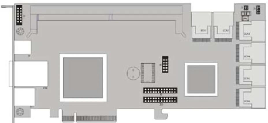
Figure 2-3, ARC-1680LP SAS RAID Controller
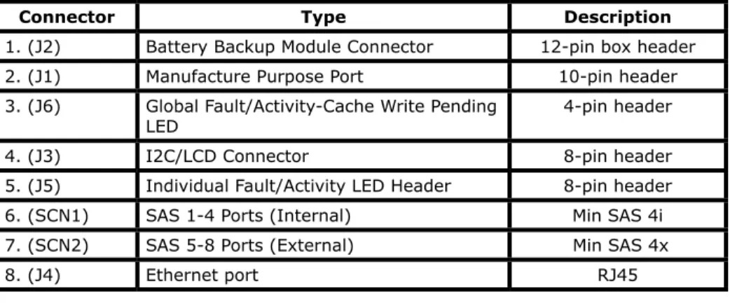
Connector Type Description
1. (J2) Battery Backup Module Connector 12-pin box header 2. (J1) Manufacture Purpose Port 10-pin header 3. (J6) Global Fault/Activity-Cache Write Pending
LED 4-pin header
4. (J3) I2C/LCD Connector 8-pin header 5. (J5) Individual Fault/Activity LED Header 8-pin header 6. (SCN1) SAS 1-4 Ports (Internal) Min SAS 4i 7. (SCN2) SAS 5-8 Ports (External) Min SAS 4x 8. (J4) Ethernet port RJ45
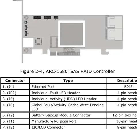
HARDWARE INSTALLATION
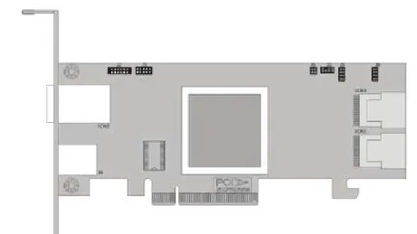
Connector Type Description
1. (J4) Ethernet Port RJ45 2. (JP2) Individual Fault LED Header 4-pin header 3. (J5) Individual Activity (HDD) LED Header 4-pin header 4. (J6) Global Fault/Activity-Cache Write Pending
LED 4-pin header
5. (J2) Battery Backup Module Connector 12-pin box header 6. (J1) Manufacture Purpose Port 10-pin header 7. (J3) I2C/LCD Connector 8-pin header 8. (SCN1) SAS 1-4 Ports (Internal) Min SAS 4i 9. (SCN2) SAS 5-8 Ports (Internal) Min SAS 4i
Table 2-4, ARC-1680i Connectors
HARDWARE INSTALLATION
Connector Type Description
Front Side
1. (SCN5) SAS 5-8 Ports (External) Min SAS 4x 2. (J4) Ethernet port RJ45 3. (J1) Manufacture Purpose Port 10-pin header 4. (J6) Global Fault/Activity-Cache Write Pending
LED 4-pin header
5. (J8) Individual Fault LED Header 8-pin header 6. (J5) Individual Fault LED Header 8-pin header 7. (J3) I2C/LCD Connector 8-pin header 8. (SCN2) SAS 5-8 Ports (Internal) Min SAS 4i 9. (SCN1) SAS 1-4 Ports (Internal) Min SAS 4i Back Side
10. (SCN4) SAS 13-16 Ports (Internal) Min SAS 4i 11. (SCN3) SAS 9-12 Ports (Internal) Min SAS 4i
Table 2-5, ARC-1680IXL-12/16 Connectors Figure 2-5, ARC-1680IXL-12/16 SAS RAID Controller
Front Side
HARDWARE INSTALLATION
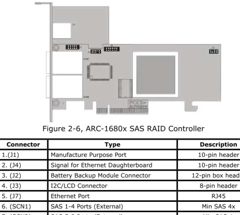
Connector Type Description
1.(J1) Manufacture Purpose Port 10-pin header 2. (J4) Signal for Ethernet Daughterboard 10-pin header 3. (J2) Battery Backup Module Connector 12-pin box header 4. (J3) I2C/LCD Connector 8-pin header 5. (J7) Ethernet Port RJ45 6. (SCN1) SAS 1-4 Ports (External) Min SAS 4x 7. (SCN2) SAS 5-8 Ports (External) Min SAS 4x
Table 2-6, ARC-1680x Connectors
Figure 2-6, ARC-1680x SAS RAID Controller
LED Status
Link LED
(Green light) When link LED illuminate that indicates the link LED is connected. Activity LED
(Blue light) The activity LED illuminate that indicates the adapter is active.
HARDWARE INSTALLATION
Tools Required
An ESD grounding strap or mat is required. Also required are stan-dard hand tools to open your system’s case.
System Requirement
The SAS RAID controller can be installed in a universal PCIe slot and requires a motherboard that:
ARC-1680 series SAS RAID controller requires: • Comply with the PCIe x8
It can work on the PCIe x1, x4, x8, and x16 signal with x8 or x16 slot M/B.
Installation Tools
The following items may be needed to assist with installing the SAS RAID controller into an available PCIe expansion slot. • Small screwdriver
• Host system hardware manuals and manuals for the disk or enclosure being installed.
Personal Safety Instructions
Use the following safety instructions to help you protect your computer system from potential damage and to ensure your own personal safety.
Warning:
High voltages may be found inside computer equipment. Before installing any of the hardware in this package or removing the protective covers of any computer equipment, turn off power switches and disconnect power cords. Do not reconnect the power cords until you have replaced the covers.
HARDWARE INSTALLATION
• Always wear a grounding strap or work on an ESD-protective mat.
• Before opening the system cover, turn off power switches and unplug the power cords. Do not reconnect the power cords until you have replaced the covers.
Electrostatic Discharge
Static electricity can cause serious damage to the electronic com-ponents on this SAS RAID controller. To avoid damage caused by electrostatic discharge, observe the following precautions:
• Do not remove the SAS RAID controller from its anti-static packaging until you are ready to install it into a computer case. • Handle the SAS RAID controller by its edges or by the metal mounting brackets at its each end.
• Before you handle the SAS RAID controller in any way, touch a grounded, anti-static surface, such as an unpainted portion of the system chassis, for a few seconds to discharge any built-up static electricity.
2.3 Installation
Use the following instructions below to install a PCIe SAS RAID controller.
Step 1. Unpack
Unpack and remove the PCIe SAS RAID controller from the pack-age. Inspect it carefully, if anything is missing or damaged, contact your local dealer.
Step 2. Power PC/Server Off
Turn off computer and remove the AC power cord. Remove the system’s cover. For the instructions, please see the computer sys-tem documentation.
Step 3. Check Memory Module
Be sure of the cache memory module is present and seated firmly in the DIMM socket (DDR2-533) for ARC1680ix-12/16/24 models.
HARDWARE INSTALLATION
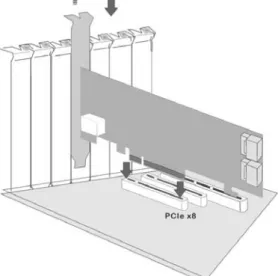
Figure 2-7, Insert SAS RAID controller into a PCIe slot
Step 5 Mount the Drives
You can connect the SAS/SATA drives to the controller through direct cable and backplane solutions. In the direct connection, SAS/SATA drives are directly connected to SAS RAID controller PHY port with SAS/SATA cables. The SAS RAID controller can support up to 28 PHY ports. Remove the front bezel from the computer chassis and install the cages or SAS/SATA drives in the computer chassis. Loading drives to the drive tray if cages are installed. Be sure that the power is connected to either the cage backplane or the individual drives.
Step 4. Install the PCIe SAS RAID Cards
To install the SAS RAID controller, remove the mounting screw and existing bracket from the rear panel behind the selected PCIe slot. Align the gold-fingered edge on the card with the selected PCIe slot. Press down gently but firmly to ensure that the card is prop-erly seated in the slot, as shown in Figure 2-7. Then, screw the bracket into the computer chassis. ARC-1680 series cards require a PCIe x8 slot.
HARDWARE INSTALLATION
In the backplane solution, SAS/SATA drives are directly connected to SAS system backplane or through an expander board. The number of SAS/SATA drives is limited to the number of slots available on the backplane. Some backplanes support daisy chain expansion to the next backplanes. The SAS RAID controller can support daisy-chain up to 8 enclosures. The maximum drive no. is 128 devices through 8 enclosures. The following figure shows how to connect the external Min SAS cable from the SAS RAID controller that has external connectors to the external drive boxes or drive enclosures.
The following table is the max no. of SAS RAID controller supported:
Disks/Enclosure Expander Disks/Controller Volume
Max No. 32 8 128 128
Figure 2-8, External connector to a drive box or drive enclosure
Note:
1. The maximum no. is 32 disk drives included in a single RAID set.
HARDWARE INSTALLATION
Figure 2-10, SAS Cable Connect to Backplane Figure 2-9, SAS Cable Connect to HD
Step 6. Install SAS Cable
HARDWARE INSTALLATION
Step 7. Install the LED Cable (option)
The preferred I/O connector for server backplanes is the Min SAS 4i internal connector. This connector has eight signal pins to support four SAS/SATA drives and six pins for the SGPIO (Serial General Purpose Input/Output) side-band signals. The SGPIO bus is used for efficient LED management and for sensing drive Locate status. See SFF 8485 for the specification of the SGPIO bus. For backplane without SGPIO supporting, Please refer to Section 2.4 LED cables for fault/activity LED cable installation.
LED Management: The backplane may contain LEDs to indicate drive status. Light from the LEDs could be transmitted to the out-side of the server by using light pipes mounted on the SAS drive tray. A small microcontroller on the backplane, connected via the SGPIO bus to a SAS RAID controller, could control the LEDs. Activ-ity: blinking 5 times/second and Fault: solid illuminated
Drive Locate Circuitry: The location of a drive may be detected by sensing the voltage level of one of the pre-charge pins before and after a drive is installed.
The following signals define the SGPIO assignments for the Min SAS 4i internal connector (SFF-8087) in the SAS RAID controller.
PIN Description PIN Description
SideBand0 SClock (Clock signal) SideBand1 SLoad (Last clock of a bit stream) SideBand2 Ground SideBand3 Ground SideBand4 SDataOut (Serial data
output bit stream) SideBand5 SDataIn (Serial data input bit stream) SideBand6 Reserved SideBand7 Reserved
Step 8. Adding a Battery Backup Module (optional)
Please refer to Appendix B for installing the BBM in your SAS RAID controller.
HARDWARE INSTALLATION
Step 9. Re-check Fault LED Cable Connections (optional)
Be sure that the proper failed drive channel information is dis-played by the fault LEDs. An improper connection will tell the user to ‘‘Hot Swap’’ the wrong drive. This can result in removing the wrong disk (one that is functioning properly) from the controller. This can result in failure and loss of system data.
Step 10. Power up the System
Throughly check the installation, reinstall the computer cover, and reconnect the power cord cables. Turn on the power switch at the rear of the computer (if equipped) and then press the power but-ton at the front of the host computer.
Step 11. Install the Controller Driver
For a new system:
• Driver installation usually takes places as part of operating sys-tem installation. Please refer to Chapter 4 Diver Installation for the detailed installation procedure.
In an existing system:
• To install the controller driver into the existing operating system. For the detailed installation procedure, please refer to the Chapter 4, Driver Installation.
Note:
For lastest release versions of drivers, please download from http://www.areca.com.tw
Step 12. Install ArcHttp Proxy Server
The SAS RAID controller firmware has embedded the web-browser McRAID storage manager. ArcHttp proxy server will launch the web-browser McRAID storage manager. It provides all of the cre-ation, management and monitor SAS RAID controller status. Please refer to the Chapter 5 for the detail ArcHttp Proxy Server Installa-tion. For SNMP agent function, please refer to Appendix C.
HARDWARE INSTALLATION
Step 13. Configure Volume Set
The controller configures RAID functionality through the McBIOS RAID manager. Please refer to Chapter 3, McBIOS RAID Manager, for the detail. The RAID controller can also be configured through the McRAID storage manager with ArcHttp proxy server installed, LCD module (refer to LCD manual) or through on-board LAN port. For this option, please refer to Chapter 6, Web Browser-Based Con-figuration.
Step 14. Determining the Boot Sequences
For PC system:
• The SAS RAID controller is a bootable controller. If your system already contains a bootable device with an installed operating system, you can set up your system to boot a second operating system from the new controller. To add a second bootable control-ler, you may need to enter setup of motherboard BIOS and change the device boot sequence so that the SAS RAID controller heads the list. If the system BIOS setup does not allow this change, your system may not configurable to allow the SAS RAID controller to act as a second boot device.
For Mac Pro system:
•The currently Mac OS X 10.4.7 or 10.5 Leopard can not directly boot up from Areca controller’s volume (We do not support the Open Firmware) on the Power Mac G5 machine and can only use as a secondary storage. All Intel based Mac Pro machines use EFI to boot (not Open Firmware, which was used for PPC Macs) the system. Areca has supported the EFI BIOS on its PCIe SAS RAID adapter. You have other alternatively to add Areca volume set on the Mac Pro bootable device listing. You can follow the following procedures to add Areca PCIe SAS RAID controller on the Mac Pro bootable device listing.
(1). Upgrade the EFI BIOS from shipping <CD-ROM>\Firmware\ Mac\ directory or from the www.areca.com.tw, if the adapters default ship with a legacy BIOS for the PC. Please follow the Ap-pendix A Upgrading Flash ROM Update Process to update the lega-cy BIOS to EFI BIOS for Mac Pro to boot up from Areca controller’s volume.
HARDWARE INSTALLATION
(2).Ghost (such as Carbon Copy Cloner ghost utility) the Mac OS X 10.4.X or 10.5 system disk on the Mac Pro to the Areca Exter-nal PCIe SAS RAID adapter volume set. Carbon Copy Cloner is an archival type of back up software. You can take your whole Mac OS X system and make a carbon copy or clone to Areca volume set like an other hard drive. You can also directly install the Mac OS X 10.5 Leopard to Areca Intel IOP Based volume set without using the Ghost utility.
(3). Power up the Mac Pro machine, it will take about 30 seconds for controller firmware ready. This periodic will let the boot up screen blank before Areca volume in the bootable device list.
2.4 SAS Cables
You can connect the end devices to each other through direct ca-bles or through the SAS expander/backplane connections. The SAS RAID controller supports daisy-chain expansion up to 8 enclosures. The following is an example of some internal SAS/SATA cables and an external SAS cable.
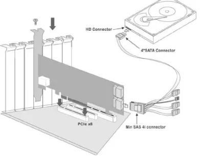
2.4.1 Internal Min SAS 4i to SATA Cable
The Min SAS 4i to SATA cables are used for connection between the SAS RAID controller internal connectors and connectors on the SAS/SATA disk drives or SAS/SATA connector backplane. The SAS controllers has 1-6 Min SAS 4i (SFF-8087) internal connec-tors, each of them can support up to four SAS/SATA drives. These adapters can be installed in a server RAID enclosure with standard SATA connectors backplane. The following diagram shows the picture of Min SAS 4i to 4*SATA cables. Backplane sup-ports SGPIO header can leverage the SGPIO function on the SAS RAID controller through the sideband cable.
The sideband cable is reserved for the backplane with header on it.
HARDWARE INSTALLATION
Figure 2-11, Internal Min SAS 4i to 4x SATA Cable
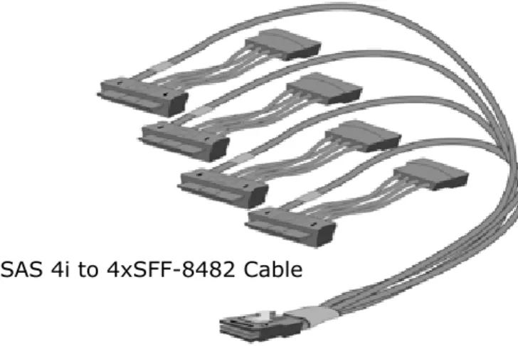
Figure 2-12, Min SAS 4i to 4xSFF-8482 Cable
2.4.2 Internal Min SAS 4i to 4xSFF-8482 Cable
These controllers can be installed in a server RAID enclosure with out a backplane. The kind of cable will attach directly to the SAS disk drives. The following diagram shows the picture of Min SAS 4i to 4xSFF-8482 cables.
HARDWARE INSTALLATION
Figure 2-13, Min SAS 4i to Min SAS 4i Cable
Figure 2-14, Min SAS 4x to Min SAS 4x Cable
2.4.3 Internal Min SAS 4i to Internal Min SAS 4i
cable
The SAS RAID controllers have 1-6 Min SAS 4i internal connec-tors, each of them can support up to four SAS/SATA signals. These adapters can be installed in a server RAID enclosure with Min SAS 4i internal connectors backplane. This Min SAS 4i cable has eight signal pins to support four SAS/SATA drives and six pins for the SGPIO (Serial General Purpose Input/Output) side-band signals. The SGPIO bus is used for efficient LED management and for sensing drive Locate status.
2.4.4 External Min SAS 4i Drive Boxes and Drive
Expanders
The Min SAS 4X external cables are used for connection between the SAS controller external connectors and connectors on the ex-ternal drive boxes or drive expanders (JBOD). The SAS controller has Min SAS 4x (SFF-8088) external connector, each of them can support up to four SAS/SATA signals.
HARDWARE INSTALLATION
Note:
A cable for the global indicator comes with your computer system. Cables for the individual drive LEDs may come with a drive cage, or you may need to purchase them.
2.5 LED Cables
There is no SGPIO supported in the most of old version SATA backplane. The SAS controller also provides two kinds of alterna-tive LED cable header to support the fault/activity status for those backplanes. The Global Indicator Connector is used by the server global indicator LED.
The following electronics schematic is the SAS RAID controller logi-cal of fault/activity header. The signal for each pin is cathode (-) side.
The following diagrams and descriptions describe each type of con-nector.
A: Individual Activity/Fault LED and Global Indicator Con-nector
Most of the backplane has supported the HDD activity from the HDD. The SAS RAID controller also provides the fault activity for fault LED. Connect the cables for the drive fault LEDs between the backplane of the cage and the respective connector on the SAS RAID controller.
HARDWARE INSTALLATION
LED Normal Status Problem Indication
Fault LED When the fault LED is solid illuminated, there is no disk present. When the fault LED is off, then disk is present and status is normal.
When the fault LED is slow blinking (2 times/sec), that disk drive has failed and should be hot-swapped immediately. When the activity LED is illuminated and fault LED is fast blinking (10 times/sec) there is rebuilding activity on that disk drive.
Figure 2-16, ARC-1680ix-8 individual LED for each channel drive and global indicator connector for computer case. Figure 2-15, ARC-1680ix-12/16/24 individual LED for each channel drive and global indicator connector for computer case.
If the system will use only a single global indicator, attach the LED to the two pins of the global activity/cache write-pending connector. The global fault pin pair connector is the overall fault signal. This signal will light up in any disk drive failure.
HARDWARE INSTALLATION
Figure 2-17, ARC-1680LP individual LED for each channel drive and global indicator connector for computer case.
Figure 2-18, ARC-1680i
individual LED for each channel drive and global indicator connector for computer case.
Figure 2-19, ARC-1680IXL-12/16 individual LED for each channel drive and global indicator connector for computer case.
HARDWARE INSTALLATION
Figure 2-20, Activity/Fault LED I2C connector connected between SAS RAID Controller & 4 SATA HDD backplane.
B: I2C Connector
You can also connect the I2C interface to a proprietary SAS/SATA backplane enclosure. This can reduce the number of activity LED and/or fault LED cables. The I2C interface can also cascade to another SAS/SATA backplane enclosure for the additional channel status display.
PIN Description PIN Description
1 Power (+5V) 2 GND 3 LCD Module Interrupt 4 Protect Key 5 LCD Module Serial Data 6 Fault/Activity Clock 7 Fault/Activity Serial Data 8 LCD Module Clock
The following picture and table is the I2C signal name description for LCD & fault/activity LED.
HARDWARE INSTALLATION
PIN Description PIN Description
SideBand0 SClock (Clock signal) SideBand1 SLoad (Last clock of a bit stream) SideBand2 Ground SideBand3 Ground SideBand4 SDataOut (Serial data
output bit stream) SideBand5 SDataIn (Serial data input bit stream) SideBand6 Reserved SideBand7 Reserved
C: SGPIO bus
The preferred I/O connector for server backplanes is the Min SAS 4i (SFF-8087) internal serial-attachment connector. This connector has eight signal pins to support four SATA drives and six pins for the SGPIO (Serial General Purpose Input/Output) sideband signals which use to replace the individual LED cable.
The SGPIO bus is used for efficient LED management and for sensing drive locate status. See SFF 8485 for the specification of the SGPIO bus. The number of drives supported can be increased, by a factor of four, by adding similar backplane to maximum of 24 drives (6 backplanes)
LED Management: The backplane may contain LEDs to indicate drive status. Light from the LEDs could be transmitted to the out-side of the server by using light pipes mounted on the SATA drive tray. A small CPLD on the backplane, connected via the SGPIO bus to a SAS RAID controller, could control the LEDs. Activity: blink-ing/controller access Fault: solid illuminated
Drive Locate Circuitry: The locate of a drive may be detected by sensing the voltage level of one of the pre-charge pins before and after a drive is installed. Fault blinking 2 times/second.
The following signal defines the SGPIO assignments for the Min SAS 4i connector (SFF-8087) in SAS RAID controller.
HARDWARE INSTALLATION
The following signal defines the sideband connector which can work with Areca sideband cable on its SFF-8087 to 4 SATA cable. The sideband header is located at backplane. For SGPIO to work properly, please connect Areca 8-pin sideband cable to the sideband header as shown above. See the table for pin definitions.
2.6 Hot-plug Drive Replacement
The RAID controller supports the ability of performing a hot-swap drive replacement without powering down the system. A disk can be disconnected, removed, or replaced with a different disk without taking the system off-line. The RAID rebuilding will be processed automatically in the background. When a disk is hot swap, the RAID controller may no longer be fault tolerant. Fault tolerance will be lost until the hot swap drive is subsequently replaced and the rebuild operation is completed.
2.6.1 Recognizing a Drive Failure
A drive failure can be identified in one of the following ways: 1. An error status message lists failed drives in the event log. 2. A fault LED illuminates on the front of RAID subsystem if failed drives are inside.
2.6.2 Replacing a Failed Drive
With RAID subsystem drive tray, you can replace a defective physical drive while your computer is still operating. When a new drive has been installed, data reconstruction will be automatically started to rebuild the contents of the disk drive.
HARDWARE INSTALLATION
Configuration Utility Operating System supported McBIOS RAID Manager OS-Independent
McRAID Storage Manager
(Via Archttp proxy server) Windows 2000/XP/Server 2003/Vista, Linux, FreeBSD, Solaris and Mac SAP Monitor (Single Admin Portal to
scan for multiple RAID units in the net-work, via ArcHttp proxy server)
Windows 2000/XP/Server 2003/Vista
SNMP Manager Console Integration Windows 2000/XP/Server 2003/Vista, Linux, FreeBSD, Solaris and Mac
2.7 Summary of the installation
The flow chart below describes the installation procedures for SAS RAID controllers. These procedures includes hardware installa-tion, the creation and configuration of a RAID volume through the McBIOS/McRAID manager, OS installation and installation of SAS RAID controller software.
The software components configure and monitor the SAS RAID controllers as following table.
Note:
The capacity of the replacement drives must be at least as large as the capacity of the other drives in the raid set. Drives of insufficient capacity will be failed immediately by the RAID adapter without starting the Automatic Data Rebuild.
HARDWARE INSTALLATION
McRAID Storage Manager
Before launching the firmware-embedded web server, McRAID storage manager through the PCIe bus, you need first to install the ArcHttp proxy server on your server system. If you need additional information about installation and start-up of this function, see the McRAID Storage Manager section in Chapter 6
SNMP Manager Console Integration • Out of Band-Using LAN Port
Before launching the controller's firmware-embedded SNMP agent, you need first to enable the firmware-embedded SNMP agent function and install the SNMP extension agent software on your server system. If you need additional information about installation and start-up this function, see the section 6.8.4 SNMP Configuration.
• In-Band-Using PCIe Bus
Before launching the SNMP agent in the sever, you need first to enable the firmware-embedded SNMP community configuration and install Areca SNMP extension agent in your server system. If you need additional information about installation and start-up the function, see the SNMP Operation & Installation section in the Appendix C
Single Admin Portal (SAP) Monitor
This utility can scan for multiple RAID units on the network and monitor the controller set status. It also includes a Disk Stress Test (DST) utility to identify marginal spec disks before the RAID unit is put into a production environment. For additional information, see the utility manual (SAP) in the packaged CD or download it from the web site http://www.areca.com.tw
BIOS CONFIGURATION
3. McBIOS RAID Manager
The system mainboard BIOS automatically configures the following SAS RAID controller parameters at power-up:
• I/O Port Address
• Interrupt Channel (IRQ) • Adapter ROM Base Address
Use McBIOS RAID manager to further configure the SAS RAID control-ler to suit your server hardware and operating system.
3.1 Starting the McBIOS RAID Manager
This section explains how to use the McBIOS RAID manager to configure your RAID system. The McBIOS RAID manager is de-signed to be user-friendly. It is a menu-driven program, residing in the firmware, which allows you to scroll through various menus and sub-menus and select among the predetermined configuration options.
When starting a system with a SAS RAID controller installed, it will display the following message on the monitor during the start-up sequence (after the system BIOS startup screen but before the operating system boots):
The McBIOS RAID manager message remains on your screen for about nine seconds, giving you time to start the configurarion menu by pressing Tab or F6. If you do not wish to enter configu-ration menu, press ESC to skip configuration immediately. When activated, the McBIOS RAID manager window appears showing a selection dialog box listing the SAS RAID controllers that are in-stalled in the system.
The legend at the bottom of the screen shows you what keys are enabled for the windows.
Bus/Dev/Fun= 1/0/0, I/0-Port=28000000h, IRQ=9, BIOS=CB00 : 0h No BIOS disk found. RAID controller BIOS not installed!
Press <Tab/F6> to enter SETUP menu. 9 second(s) left <ESC to Skip>..
ARC-1680 PCIEx4 RAID Controller - DRAM: 256(MB) / #Channels: 16
BIOS CONFIGURATION
Areca Technology Corporation RAID Setup <V1.40, 2006/08/8>
ArrowKey Or AZ:Move Cursor, Enter: Select, **** Press F10 (Tab) to Reboot **** Select An Adapter To Configure
( 001/ 0/0) I/O=28000000h, IRQ = 9
Use the Up and Down arrow keys to select the controller you want to configure. While the desired controller is highlighted, press the
Enter key to enter the main menu of the McBIOS RAID manager.
3.2 McBIOS RAID manager
The McBIOS RAID manager is firmware-based and is used to con-figure RAID sets and volume sets. Because the utility resides in the SAS RAID controller firmware, operation is independent of any operating systems on your computer. This utility can be used to:
• Create RAID sets, • Expand RAID sets,
I/O Port Addr : 28000000h, F2(Tab): Select Controller, F10: Reboot System
ArrowKey Or AZ:Move Cursor, Enter: Select, ESC: Escape, L:Line Draw, X: Redraw
Areca Technology Corporation RAID Controller
Main Menu Raid Set Function Volume Set Function Physical Drives Raid System Function Hdd Power Management Ethernet Configuration View System Events Clear Event Buffer Hardware Monitor System information
Quick Volume/Raid Setup
Verify Password
Note:
T h e m a n u f a c t u r e default password is set to 0000; this p a s s w o r d c a n b e modified by selecting Change Passwordin the Raid System Function section.
BIOS CONFIGURATION
3.4 Designating Drives as Hot Spares
Any unused disk drive that is not part of a RAID set can be desig-nated as a hot spare. The “Quick Volume/Raid Setup” configuration will add the spare disk drive and automatically display the appro-priate RAID level from which the user can select. For the “Raid Set Function” configuration option, the user can use the “Create Hot Spare” option to define the hot spare disk drive.
When a hot spare disk drive is being created using the “Create Hot Spare” option (in the “Raid Set Function”), all unused physical de-vices connected to the current controller appear:
Choose the target disk by selecting the appropriate check box. Press Enter key to select a disk drive, and press Yes in the “Cre-ate Hot Spare” to design“Cre-ate it as a hot spare.
• Add physical drives, • Define volume sets, • Modify volume sets,
• Modify RAID level/stripe size, • Define pass-through disk drives, • Modify system functions and • Designate drives as hot spares.
3.3 Configuring Raid Sets and Volume Sets
You can configure RAID sets and volume sets with McBIOS RAID manager automatically. Using “Quick Volume/Raid Setup” or manu-ally using “Raid Set/Volume Set Function”. Each configuration method requires a different level of user input. The general flow of operations for RAID set and volume set configuration is:
Step Action
1 Designate hot spares/pass-through drives (optional). 2 Choose a configuration method.
3 Create RAID sets using the available physical drives.
4 Define volume sets using the space available in the RAID set.
5 Initialize the volume sets and use volume sets (as logical drives) in the host OS.
BIOS CONFIGURATION
3.5 Using Quick Volume /Raid Setup
Con-figuration
“Quick Volume / Raid Setup configuration” collects all available drives and includes them in a RAID set. The RAID set you created is associated with exactly one volume set. You will only be able to modify the default RAID level, stripe size and capacity of the new volume set. Designating drives as hot spares is also possible in the “Raid Level” selection option. The volume set default settings will be:
Parameter Setting Volume Name ARC-1680-VOL#00 SCSI Channel/SCSI ID/SCSI LUN 0/0/0
Cache Mode Write Back Tag Queuing Yes
The default setting values can be changed after configuration is completed. Follow the steps below to create arrays using the “RAID Set / Volume Set” method:
Step Action
1 Choose “Quick Volume /Raid Setup” from the main menu. The available RAID levels with hot spare for the current volume set drive are displayed. 2 It is recommended that you use drives of the same capacity in a specific
array. If you use drives with different capacities in an array, all drives in the RAID set will be set to the capacity of the smallest drive in the RAID set.
The numbers of physical drives in a specific array determines which RAID levels that can be implemented in the array.
RAID 0 requires 1 or more physical drives. RAID 1 requires at least 2 physical drives. RAID 10(1E) requires at least 3 physical drives. RAID 3 requires at least 3 physical drives. RAID 5 requires at least 3 physical drives. RAID 3 +Spare requires at least 4 physical drives. RAID 5 + Spare requires at least 4 physical drives. RAID 6 requires at least 4 physical drives.
RAID 6 + Spare requires at least 5 physical drives.
Highlight the desired RAID level for the volume set and press the Enter
BIOS CONFIGURATION
3.6 Using RAID Set/Volume Set Function
Method
In “Raid Set Function”, you can use the “Create Raid Set” function to generate a new RAID set. In “Volume Set Function”, you can use the “Create Volume Set” function to generate an associated volume set and configuration parameters.
If the current controller has unused physical devices connected, you can choose the “Create Hot Spare” option in the “Raid Set Function” to define a global hot spare. Select this method to con-figure new RAID sets and volume sets. The “Raid Set/Volume Set Function” configuration option allows you to associate volume sets with partial and full RAID sets.
3 The capacity for the current volume set is entered after highlighting the desired RAID level and pressing the Enter key.
The capacity for the current volume set is displayed. Use the UP and
DOWN arrow keys to set the capacity of the volume set and press the
Enter key to confirm. The available stripe sizes for the current volume set are then displayed.
4 Use the UP and DOWN arrow keys to select the current volume set stripe size and press the Enter key to confirm. This parameter specifies the size of the stripes written to each disk in a RAID 0, 1, 10(1E), 5 or 6 volume set. You can set the stripe size to 4 KB, 8 KB, 16 KB, 32 KB, 64 KB, or 128 KB. A larger stripe size provides better read performance, especially when the computer preforms mostly sequential reads. How-ever, if the computer preforms random read requests more often, choose a smaller stripe size.
5 When you are finished defining the volume set, press the Yes key to confirm the “Quick Volume And Raid Set Setup” function.
6 Foreground (Fast Completion) Press Enter key to define fast initialization or selected the Background (Instant Available) or No Init (To Rescue Vol-ume). In the “Background Initialization”, the initialization proceeds as a background task, the volume set is fully accessible for system reads and writes. The operating system can instantly access to the newly created arrays without requiring a reboot and waiting the initialization complete. In “Foreground Initialization”, the initialization proceeds must be com-pleted before the volume set ready for system accesses. In “No Init”, there is no initialization on this volume.
7 Initialize the volume set you have just configured
8 If you need to add additional volume set, using main menu “Create Vol-ume Set” function.
BIOS CONFIGURATION
Step Action
1 To setup the hot spare (option), choose “Raid Set Function” from the main menu. Select the “Create Hot Spare” and press the Enter key to define the hot spare.
2 Choose “RAID Set Function” from the main menu. Select “Create Raid Set” and press the Enter key.
3 The “Select a Drive For Raid Set” window is displayed showing the SAS/ SATA drives connected to the SAS RAID controller.
4 Press the UP and DOWN arrow keys to select specific physical drives. Press the Enter key to associate the selected physical drive with the cur-rent RAID set.
It is recommended that you use drives of the same capacity in a specific array. If you use drives with different capacities in an array, all drives in the RAID set will be set to the capacity of the smallest drive in the RAID set.
The numbers of physical drives in a specific array determines which RAID levels that can be implemented in the array.
RAID 0 requires 1 or more physical drives. RAID 1 requires at least 2 physical drives. RAID 10(1E) requires at least 3 physical drives. RAID 3 requires at least 3 physical drives. RAID 5 requires at least 3 physical drives. RAID 6 requires at least 4 physical drives. RAID 30 requires at least 6 physical drives. RAID 50 requires at least 6 physical drives. RAID 60 requires at least 8 physical drives.
5 After adding the desired physical drives to the current RAID set, press the Enter to confirm the “Create Raid Set” function.
6 An “Edit The Raid Set Name” dialog box appears. Enter 1 to 15 alphanu-meric characters to define a unique identifier for this new RAID set. The default RAID set name will always appear as Raid Set. #. Press Enter to finish the name editing.
7 Press the Enter key when you are finished creating the current RAID set. To continue defining another RAID set, repeat step 3. To begin vol-ume set configuration, go to step 8.
8 Choose the “Volume Set Function” from the main menu. Select “Create Volume Set” and press the Enter key.
9 Choose a RAID set from the “Create Volume From Raid Set” window. Press the Yes key to confirm the selection.
BIOS CONFIGURATION
3.7 Main Menu
The main menu shows all functions that are available for executing actions, which is accomplished by clicking on the appropriate link.
Note:
The manufacture default password is set to 0000; this password can be modified by selecting “Change Password” in the “Raid System Function” section.
I/O Port Addr : 28000000h, F2(Tab): Select Controller, F10: Reboot System
ArrowKey Or AZ:Move Cursor, Enter: Select, ESC: Escape, L:Line Draw, X: Redraw
Areca Technology Corporation RAID Controller
Main Menu Raid Set Function Volume Set Function Physical Drives Raid System Function Hdd Power Management Ethernet Configuration View System Events Clear Event Buffer Hardware Monitor System information
Quick Volume/Raid Setup
Verify Password
10 Choosing Foreground (Fast Completion) Press Enter key to define fast initialization or selected the Background (Instant Available) or No Init (To Rescue Volume). In the “Background Initialization”, the initialization proceeds as a background task, the volume set is fully accessible for system reads and writes. The operating system can instantly access to the newly created arrays without requiring a reboot and waiting the initialization complete. In “Foreground Initialization”, the initialization proceeds must be completed before the volume set ready for system accesses. In “No Init”, there is no initialization on this volume.
11 If space remains in the RAID set, the next volume set can be configured. Repeat steps 8 to 10 to configure another volume set.
BIOS CONFIGURATION
Option Description
Quick Volume/Raid Setup Create a default configuration based on the number of physical disk installed
Raid Set Function Create a customized RAID set Volume Set Function Create a customized volume set Physical Drives View individual disk information Raid System Function Setup the RAID system configuration Hdd Power Management Manage HDD power based on usage patterns Ethernet Configuration Ethernet LAN setting
View System Events Record all system events in the buffer Clear Event Buffer Clear all information in the event buffer Hardware Monitor Show the hardware system environment status System Information View the controller system information
This password option allows user to set or clear the RAID control-ler’s password protection feature. Once the password has been set, the user can only monitor and configure the RAID controller by pro-viding the correct password. The password is used to protect the internal RAID controller from unauthorized entry. The controller will prompt for the password only when entering the main menu from the initial screen. The RAID controller will automatically return to the initial screen when it does not receive any command in twenty seconds.
3.7.1 Quick Volume/RAID Setup
“Quick Volume/RAID Setup” is the fastest way to prepare a RAID set and volume set. It requires only a few keystrokes to com-plete. Although disk drives of different capacity may be used in the RAID Set, it will use the capacity of the smallest disk drive as the capacity of all disk drives in the RAID Set. The “Quick Vol-ume/RAID Setup” option creates a RAID set with the following properties:
1. All of the physical drives are contained in one RAID set. 2. The RAID level, hot spare, capacity, and stripe size options are selected during the configuration process.
3. When a single volume set is created, it can consume all or a portion of the available disk capacity in this RAID set.
BIOS CONFIGURATION
I/O Port Addr : 28000000h, F2(Tab): Select Controller, F10: Reboot System
ArrowKey Or AZ:Move Cursor, Enter: Select, ESC: Escape, L:Line Draw, X: Redraw
Areca Technology Corporation RAID Controller
Main Menu Raid Set Function Volume Set Function Physical Drives Raid System Function Hdd Power Management Ethernet Configuration View System Events Clear Event Buffer Hardware Monitor System information
Quick Volume/Raid Setup
Total 5 Drives Raid 0 Raid 1 + 0 Raid 1 + 0 + Spare Raid 3 Raid 5 Raid 3 + Spare Raid 5 + Spare Raid 6 Raid 6 + Spare
If volume capacity will exceed 2TB, controller will show the “Greater Two TB Volume Support” sub-menu.
• No
It keeps the volume size with max. 2TB limitation. • LBA 64
This option use 16 bytes CDB instead of 10 bytes. The maximum volume capacity up to 512TB.
I/O Port Addr : 28000000h, F2(Tab): Select Controller, F10: Reboot System
ArrowKey Or AZ:Move Cursor, Enter: Select, ESC: Escape, L:Line Draw, X: Redraw
Areca Technology Corporation RAID Controller
Main Menu Raid Set Function Volume Set Function Physical Drives Raid System Function Hdd Power Management Ethernet Configuration View System Events Clear Event Buffer Hardware Monitor System information
Quick Volume/Raid Setup
Total 5 Drives Raid 0 Raid 1 + 0 Raid 1 + 0 + Spare Raid 3 Raid 5 Raid 3 + Spare Raid 5 + Spare Raid 6 Raid 6 + Spare Raid 0
Greater Two TB Volume Support No
Use 64bit LBA Use 4K Block
No
4. If you need to add an additional volume set, use the main menu “Create Volume Set” function.
The total number of physical drives in a specific RAID set deter-mine the RAID levels that can be implemented within the RAID set. Select “Quick Volume/Raid Setup” from the main menu; all possible RAID level will be displayed on the screen.
BIOS CONFIGURATION
This option works on different OS which supports 16 bytes CDB. Such as:
Windows 2003 with SP1 Linux kernel 2.6.x or latter
• Use 4K Block
It change the sector size from default 512 Bytes to 4k Bytes. the maximum volume capacity up to 16TB. This option works under Windows platform only. And it can not be converted to “Dynamic Disk”, because 4k sector size is not a standard format.
For more details, please download pdf file from ftp://ftp. areca.com.tw/RaidCards/Documents/Manual_Spec/ Over2TB_050721.zip
A single volume set is created and consumes all or a portion of the disk capacity available in this RAID set. Define the capacity of volume set in the “Available Capacity” popup. The default value for the volume set, which is 100% of the available capacity, is displayed in the selected capacity. use the UP and DOWN arrow key to set capacity of the volume set and press Enter key to ac-cept this value. If the volume set uses only part of the RAID set capacity, you can use the “Create Volume Set” option in the main menu to define additional volume sets.
I/O Port Addr : 28000000h, F2(Tab): Select Controller, F10: Reboot System
ArrowKey Or AZ:Move Cursor, Enter: Select, ESC: Escape, L:Line Draw, X: Redraw
Areca Technology Corporation RAID Controller
Main Menu Raid Set Function Volume Set Function Physical Drives Raid System Function Hdd Power Management Ethernet Configuration View System Events Clear Event Buffer Hardware Monitor System information
Quick Volume/Raid Setup
Total 5 Drives Raid 0 Raid 1 + 0 Raid 1 + 0 + Spare Raid 3 Raid 5 Raid 3 + Spare Raid 5 + Spare Raid 6 Raid 6 +Spare Raid 6 Available Capacity : 2400.0GB Selected Capacity: 2400.0GB
Stripe Size This parameter sets the size of the stripe written to each disk in a RAID 0, 1, 10, 5, or 6 logical drive. You can set the stripe size to 4 KB, 8 KB, 16 KB, 32 KB, 64 KB, or 128 KB.