Wireless LAN
Access Network Architecture for
Mobile Operators
A
BSTRACT
The evolution of IP-based office applications has created a strong demand for public wireless broadband access technology offering capacity far beyond current cellular systems. Wireless LAN access technology provides a perfect broadband complement for the operators’ existing GSM and GPRS services in an indoor environment. Most commercial public wireless LAN solutions have only modest authentication and roaming capability compared to traditional cellular networks. This article describes a new wireless LAN system archi-tecture that combines the WLAN radio access technology with mobile operators’ SIM-based sub-scriber management functions and roaming infra-structure. In the defined system the WLAN access is authenticated and charged using GSM SIM. This solution supports roaming between cellular and WLAN access networks and is the first step toward an all-IP network architecture. The proto-type has been implemented and publicly verified in a real mobile operator network.
I
NTRODUCTION
Seamless access to modern office tools is one of the most valuable assets for mobile business pro-fessionals today. Most corporate information sys-tems and databases can be accessed remotely through the Internet (IP) backbone, but the high bandwidth demand of typical office applications, such as large e-mail attachment downloading, often exceeds the transmission capacity of cellu-lar networks. Mobile professionals are looking for a public wireless access solution that could cover the demand for data-intensive applications and enable smooth online access to corporate data services.
Wireless local area networking (WLAN) radio technology provides superior bandwidth compared to any cellular technology. The state-of-the-art Wi-Fi™ wireless LAN standard (IEEE 802.11b) offers a maximum throughput of 11 Mb/s over a license exempt 2.4 GHz frequency band [1, 2]. The maximum data rate of a single
user in a public WLAN radio network is 11 Mb/s (typical 6.5 Mb/s), while a General Packet Radio Service (GPRS) handset offers a data rate up to 172 kb/s (typically 42 kb/s) and the third-genera-tion terminal up to 2 Mb/s (typically 144 kb/s). From the end users’ perspective the perfor-mance difference is huge, which makes WLAN a competitive option to cellular data indoors.
Most WLAN terminals are laptops or PDAs with separate WLAN network adapters. The market analysts forecast a major growth of WLAN PC card market in 2001. The WLAN terminal business is gradually moving toward more integrated devices; the leading high-end laptop models shall have integrated wireless LAN interfaces during 2001. Furthermore, the terminal category is expanding with WLAN PDA phones and integrated PDA devices.
The business professionals’ desire for broad-band public data access and the rapidly growing WLAN terminal penetration create a fascinating business opportunity for mobile operators to extend their services to cover WLAN access. Today, there are about 50 million mobile laptop users, of which 30 million also have GSM sub-scription [3]. WLAN can complement mobile operators’ traditional wide-area GPRS and GSM service portfolio by offering a cost-efficient wire-less broadband data solution indoors. Target places for WLAN access services are airports, railway stations, hotels, business parks, and office buildings where most mobile laptop users typically work.
The key question is how to utilize mobile operator strengths: large GSM customer base, cellular infrastructure investments, and well estab-lished roaming agreements in operator WLAN networks. The authors have been involved in the development of a new WLAN system architecture which is targeted to mobile operators. The defined solution, called an operator WLAN
(OWLAN) system, combines GSM subscriber management and billing mechanisms with WLAN access technology. The OWLAN enables IP roam-ing between different operator access networks. The operator WLAN solution is available for
Juha Ala-Laurila, Jouni Mikkonen, and Jyri Rinnemaa, Nokia Mobile Phones
any wireless LAN terminal device that provides GSM SIM card reader and defined operator WLAN signaling module. The reference system was implemented as part of the company research project and was successfully piloted in a real mobile operator network in 2000. The obser-vations and learnings from the trial proved the usability of the concept, and the first commercial system was launched in July 2001 and has been successfully piloted by several mobile operators.
This article describes the OWLAN architec-ture, main system components and their func-tionality. The focus is on the SIM based authentication, roaming and billing mechanisms.
O
PERATOR
WLAN
S
OLUTION
O
VERVIEW
D
ESIGNO
BJECTIVESThe future mobile operator network shall be a combination of several radio communication technologies, such as GSM/GPRS, the third gen-eration radio access and wireless LAN. A single subscriber identity should be used in all access networks to enable smooth roaming and seam-less service availability. The operator WLAN system should maintain compatibility with the existing GSM/GPRS core network roaming and billing functions [4, 5], which minimizes the number of modifications in the GSM core equip-ment and the standardization effort needed. A GSM Subscriber Identity Module (SIM) is a nat-ural choice for WLAN subscriber management since it is widely deployed and enables roaming to existing GSM/GPRS handsets and networks.
In the first phase the focus of WLAN business is on data applications. Thus, the OWLAN
sys-tem should be optimized for terminal initiated IP data services, which reduces system complexity. The evolution to all-IP services in the wireless LAN shall follow in the next step as mobile oper-ator all-IP service infrastructure is available.
To minimize the installation costs and com-plexity, the OWLAN should utilize the existing GPRS charging system. GPRS operators have defined a mechanism for exchanging billing data between operators’ networks [6]. The same mechanism should be used for transmitting WLAN charging records.
O
PERATORWLAN S
YSTEMA
RCHITECTURE The OWLAN system architecture, depicted in Fig. 1, consists of the public LAN access net-work and the cellular operator site, which com-municate over the IP backbone. The main design challenge was to transport standard GSM sub-scriber authentication signaling [4] from the ter-minal to the cellular site using the IP protocol framework. One could call the resulting operator WLAN architecture the first instance of a mobile operator all-IP network.The OWLAN system contains four key
physi-■Figure 1.An overview of the operator WLAN system architecture.
SS7 Operator IP core GPRS charging gateway Cellular operator site Cellular operator core 1) Terminal authentication to WLAN RAN with SIM
3) GSM authentication and charging messaging
2) SIM authentication and user accounting signalling over IP Public WLAN access GPRS RAN GSM base station WLAN terminal with SIM 2,4 GHz 11 Mb/s WLAN access
points controllerAccess GGSN
SGSN
Authentication server
MSC/ HLR
■Table 1.OWLAN vs. GPRS network elements.
OWLAN GPRS Function
Authentication server (AS) SGSN User authentication, access billing Access controller (AC) GGSN End point of IP packet network,
IP address allocation
Access point (AP) BTS Radio coverage
cal entities: authentication server, access con-troller, access point, and mobile terminal (Fig. 1). The system architecture resembles a GPRS net-work. Each system component has a counterpart in the GPRS network, as illustrated in Table 1.
The significant difference compared to the GPRS architecture is that in the OWLAN system only the control signaling data is transported to the cellular core. The access controller routes user data packets directly to the IP backbone, which is used for accessing the public and private services. This architecture avoids the GPRS kind of roam-ing complexity since the user’s IP traffic does not have to be carried via the cellular core to the home network. Consequently, the operator WLAN approach decreases the load of the cellular core.
The subscriber authentication works as follows. First a WLAN terminal associates with a WLAN access point, gets an IP address from the access controller, and initiates the network authentica-tion by sending a dedicated authenticaauthentica-tion request to the access controller (1). The access controller relays the authentication request to the authenti-cation server (2), which implements the gateway between the access network and the GSM signal-ing network. The authentication server queries the GSM home location register (HLR) for the authentication data and performs user authentica-tion using this informaauthentica-tion (3).
S
YSTEM
E
LEMENTS
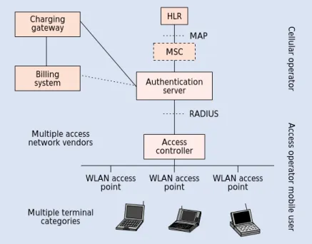
Figure 2 depicts the main operator WLAN sys-tem elements and interfaces in more detail.
T
HEA
UTHENTICATIONS
ERVERThe authentication server is the main control point of the OWLAN subscriber management. A single entity may support several access con-trollers and provide authentication and billing ser-vices for thousands of roaming users in different access zones. The authentication server communi-cates with the access controller using RADIUS
authentication protocol [7], which is a de facto authentication, authorization, and accounting (AAA) protocol in the IP industry. When the user disconnects, the authentication server receives the accounting data from the access con-troller, converts it into GPRS billing format [6], and issues the ticket to the cellular billing system.
The authentication server hides the cellular infrastructure from the access network. It pro-vides a gateway to the cellular core network ele-ments, namely the GSM home location register (HLR) and GPRS charging gateway. The authentication server sends standard GSM authentication signaling to the HLR using the SS7 signaling network that connects various operator networks together. The cellular net-work identifies the user with GSM International Mobile Subscriber Identity (IMSI) code stored in the SIM card.
In the prototype system the authentication server has been implemented using a Windows NT server platform that has been connected directly to the Nokia Mobile Switching Centre (MSC). An IP-compliant vendor-specific protocol carries the authentication requests from the AS to the MSC. Figure 2 shows the applied configura-tion in which the MSC offers a redundant high-performance MAP interface and allows us to balance the signaling traffic from the WLAN with normal GSM signaling. In this setup WLAN requests can never block GSM signaling. Alterna-tively, the authentication server could be imple-mented with a native MAP interface.
A predefined bit pattern in the HLR sub-scriber service profile indicates the WLAN service subscription. The authentication server always checks if the roaming user has subscribed to the WLAN service. In the future the service profile could be extended to include, for example, the quality of service class of a WLAN subscriber. The current GSM standard does not define a WLAN service bit pattern, and the service profile bit interpretation rules are operator-dependent.
A
CCESSC
ONTROLLERThe access controller provides an Internet gate-way between the radio access network and the fixed IP core. It allocates IP addresses to the mobile terminals and maintains a list of the authenticated terminals’ IP addresses. The AC acts as a traffic filter monitoring the address of each incoming or outgoing IP packet and discard-ing the packets that come from a nonauthenticat-ed terminal. The access controller separates the mobile terminals using a terminal IP address and a unique WLAN link-layer-specific MAC address. The MAC address verification ensures that a duplicate IP address cannot simultaneously be used by a hostile user. The access controller gath-ers accounting information for billing purposes. The access controller prototype has been imple-mented using an IP router platform, more pre-cisely, Nokia IPSO IP330 series router.
T
HEW
IRELESSLAN A
CCESSP
OINT The access point offers a wireless Ethernet link between the mobile terminal and the fixed LAN. Access points are connected to the same LAN with the access controller. The access points are Wi-Fi compliant and support the data rates of 1,■Figure 2.The elements of the OWLAN system.
Cellular operator MAP RADIUS Multiple access network vendors Multiple terminal categories WLAN access point
Access operator mobile user
HLR Access controller Authentication server MSC Charging gateway Billing system WLAN access point WLAN access point
2, 5.5, and 11 Mb/s [1, 2]. The typical coverage range of a single Wi-Fi access point is 50–100 m indoors. The coverage can be extended using directional antennas and radio network planning tools. The access point offers a shared radio interface. Consequently, the amount of active terminals affects the perceived user data rate. If there are no other terminals in the same access point, a single user may use the complete 11 Mb/s radio link. This is one significant difference from GPRS radio access [5].
M
OBILET
ERMINALOWLAN service is available for any terminal with WLAN radio access capability, a SIM reader, and a SIM authentication software module. The end user may deploy either a WLAN card with an integrated SIM reader or a WLAN card and an external smart card reader. Laptop vendors have also indicated that some laptop models shall have integrated smart card readers in the future.
The OWLAN terminal may detect the correct roaming WLAN network by using predefined net-work profiles that contain the list of the roaming partners’ radio network identifiers. When enter-ing a new location the terminal compares the names of available WLAN networks with the roaming profile and associates to the correct WLAN. The operator may distribute the profiles, say, in a SIM card or using a Web server.
S
YSTEM
O
PERATION
The requirement to maintain compatibility with existing WLAN devices and the cellular core implicitly lead to an architecture in which the nec-essary SIM specific signaling messages are trans-ported using the IP protocol. The IP approach makes an OWLAN system independent of the WLAN standard and allows us to deploy the same concept for future 5 GHz WLAN systems, such as IEEE 802.11 and HIPERLAN/2.
The functional division between the access controller and the authentication server keeps the
complexity of the core network low. The comput-ing-intensive IP packet filtering and routing func-tions reside on the access network side where the processing load can be distributed among a num-ber of access controllers. This improves system scalability and robustness. Figure 3 illustrates the resulting control plane architecture.
The core component of the mobile terminal software is the Roaming Control module, which offers a graphical control user interface to roam-ing services. This module communicates with the SIM card. The operator WLAN-specific Net-work Access Authentication and Accounting Protocol (NAAP) protocol encapsulates GSM authentication messages inside IP packets. The NAAP utilizes a connectionless User Datagram Protocol (UDP) transport layer but includes a retransmission mechanism that ensures reliable relay of the control messages.
The key component of the access controller is the Access Manager which controls IP routing and collects accounting statistics. The RADIUS protocol [7] carries SIM specific authentication parameters inside vendor specific attributes while the accounting data is submitted using standard RADIUS accounting attributes [8].
The most important module in the authenti-cation server is the Authentiauthenti-cation Controller which handles the RADIUS authentication mes-sages and communicates with the GSM core. The Accounting module receives and stores the accounting information from the access network. The Accounting module interfaces with the GPRS charging gateway using GTP’ billing pro-tocol [6]. There is no uniquely defined open GTP’ interface available, but rather there exists a combination of several GTP’ versions and vari-ous billing data formats. The authentication server offers an open FTP interface which can be used for transferring the accounting data directly to various billing systems. The following paragraphs describe the key system procedures, such as authentication, billing and secure access to the corporate network in detail.
■Figure 3.OWLAN control plane architecture.
802.11 802.11 Ethernet
IP IP
TCP UDP
Mobile terminal Access point
Ethernet WANlink
UDP TCP IP Access controller WAN link TCP/UDP IP Authentication server Auth. controller RADIUS RADIUS RADIUS authentication transmissionCDR RADIUS accounting MAP link to HLR IP-SIM authentication signaling NAAP NAAP SIM Roaming control GTP' GTP' Ethernet TCP/UDP IP Charging gateway Ethernet Access manager Accounting
A
UTHENTICATIONThe core part of the operator wireless LAN sys-tem is the SIM-based authentication. The access controller acts as a relay between the terminal and the authentication server. The authentica-tion sequence is as follows:
The first step is to activate the user terminal with the personal identity number (PIN). The SIM card and user identity are secured with PIN code protection. When the authentication phase is started, the software prompts the user for the PIN code. This functionality is equivalent to GSM, and makes it impossible to use a stolen SIM card that has PIN query enabled without knowledge of the correct PIN code.
The phases of the SIM-based authentication are illustrated in Fig. 4. The steps are numbered both in the figure and in the text below. Initially, the terminal locates the access controller in the network by sending a NAAP solicitation mes-sage to which the access controller replies (1). After receiving the IP address of the access con-troller, the terminal sends the initial authentica-tion request to the access controller, where the IMSI is encapsulated into the Network Access Identifier (NAI) (2). NAI is a well-known part of the standard IETF AAA framework [9]. The domain part of the NAI identifies the home operator domains, e.g. [email protected]. The access controller and RADIUS infra-structure use the domain part for relaying the authentication request to the correct authentica-tion server (3).
The authentication server requests GSM triplets from the home location register using
an MSC connection (4). Then the authentica-tion server sends the GSM RAND to the mobile terminal along with a message authenti-cation code calculated over the RAND (5, 6). The message authentication code authenticates the cellular network to the terminal, enabling mutual authentication. The terminal calculates the message authentication code and compares it to the one it received from the network (7). If the calculated message authentication code does not match with the received one, the ter-minal can suspect a fraudulent service and stop answering the authentication request. This mechanism makes it impossible for an attacker to gather RAND and SRES pairs from the IMSI, and thus makes it impossible to find out the secret key Ki stored on the SIM card. The message authentication procedure utilizes the HMAC mechanism presented in [10]. Next the terminal calculates the signed response (SRES) using the algorithms stored on the SIM card and also calculates a message authentication code over the SRES (8).
The terminal sends the response to the access controller which relays it to the authentication server (9, 10). The authentication server verifies the response by calculating the similar message authentication code over the SRES (11). The authentication server sends the result code of the authentication to the access controller (12). If the authentication was successful, the access con-troller sends the authentication server an indica-tion that a new accounting session has been started (13). Finally, the access controller enables routing for the terminal data packets, and sends the acknowledgment to the terminal (14, 15).
■Figure 4.The SIM-based authentication sequence.
AC address solicitation and advertisement
MT:
AC_MT_AUTHSTART_RESP (RAND, MAC_RAND)
AC_MT_AUTHANSWER_RESP (result) MT_AC_AUTHSTART_REQ (IMSI,nonce) AC_AS_AUTHSTART_REQ (IMSI,nonce) AS_MSC_GETTRIPLETS_REQ (IMSI) MSC_AS_GETRIPLETS_RESP (triplets) AC_AS_AUTHANSWER_REQ (MAC,SRES) AC_AS_STARTACCOUNTING_REQ AS_AC_AUTHSTART_RESP (IMSI,nonce) AS_AC_AUTHANSWER_RESP (result) AS_AC_STARTACCOUNTING_RESP MT_AC_AUTHSTART_REQ (MAC_SRES) 1 2 6 3 4 5 7 9 AC: AS: MSC: MT verifies MAC_RAND AS verifies MAC_SRES 8 MT generates MAC_SRES MT checks result 11 12 13 14 10 15
The authentication procedure may be abort-ed due to the following reasons: the IMSI is not known in HLR, the WLAN service has not been subscribed, the access operator does not support roaming of the specific IMSI, or the authentica-tion server does not receive the triplets from the HLR. In these cases, the terminal remains nonauthenticated and the access controller does not route the IP traffic of the terminal.
During the authentication sequence the authentication server sends the terminal and the access controller a session lifetime value, which indicates how long the authenticated session is valid. When the session lifetime expires in the access controller or the terminal disconnects, the access controller closes the terminal’s connec-tion. It also notifies the authentication server, which closes the accounting session for the ter-minal. The terminal must initiate a reauthentica-tion sequence before the session lifetime expires, if it wishes to continue the session. The reau-thentication procedure allows the operator to grant an access that is valid only for a certain period. This is a useful feature for prepaid sys-tems as well as for environments where charging could be bound to certain access times. This also allows the operator to authenticate the terminal periodically during an active session just like in the GSM system.
A
CCOUNTING ANDB
ILLINGThe access controller monitors the data traffic and periodically sends the traffic statistics infor-mation to the authentication server. The follow-ing accountfollow-ing methods are supported:
• Time-based: connection start time and end time are recorded
• Volume-based: the amount of transferred data is recorded
• Flat rate
The authentication server converts the account-ing data to standard GPRS chargaccount-ing data record (CDR) format. WLAN CDRs are marked with a WLAN-specific identifier code. More details on the CDR format can be found in [6].
The authentication server verifies the received accounting data related to an authenti-cated terminal (IMSI). This ensures that charg-ing records are not generated for a connection that has not been properly authenticated. Fur-thermore, accounting data is protected using the shared secret mechanism in RADIUS pro-tocol [7]. This mechanism prevents fraudulent insertion of accounting data in the IP network side since the access controller and authentica-tion server that share the secret key notice if the data has been altered during transmission. The shared secret key is entered in the access controller and authentication server during sys-tem configuration. The transferred data can also be encrypted using IP Security (IPSEC) protocol [11] between access controller and authentication server.
Finally, the authentication server delivers the generated CDRs to the charging gateway or billing system. The explicit rules according to which the connection is eventually billed are configured in the back-end process of the opera-tor billing system.
R
OAMING TOF
OREIGNWLAN N
ETWORKS Mobile operator consortia have the infra-structure and the culture to support roaming between different access networks as well as between operator networks. Unlike most Inter-net service providers, mobile operators have the infrastructure and the culture to support roam-ing between different access networks as well as between operator networks. The mobile opera-tors have agreed on how to exchange theauthen-■Figure 5.WLAN roaming to a foreign operator network.
4) Billing data exchange as in GSM
3) Billing info stored to GPRS/GSM billing system
2) Authentication to HLR using MAP
1) SIM authenticationsignaling Roaming user, operator A SIM 2,4 GHz 11 Mb/s WLAN RAN WLAN access points WLAN access points Internet core HLR B HLR A SS7 Operator A IP network Cellular operator A GPRS core Cellular operator B GPRS core Operator B IP network Access controller Access controller Auth. server Auth. server Charging gateway Billing system Charging gateway Billing system
tication and accounting data between the roam-ing and the home operatotr. The existroam-ing opera-tor billing systems are also capable of exchanging accounting information with each other. Figure 5 illustrates how the operator-to-operator roaming scenario works in the operator WLAN system.
First, the roaming mobile terminal associ-ates to the foreign operator WLAN network and initializes authentication by sending an authentication request to the access controller, which relays it to the authentication server (1). The authentication server analyzes the IMSI and verifies that the operators have a valid roaming agreement for WLAN services. Next, the authentication server sends the authentica-tion query to the correct HLR using the GSM SS7 network (2) [4]. The corresponding HLR responds with user profile and authentication triplets, and the authentication procedure is completed in a normal way. After the terminal disconnects, the authentication server sends the charging record to the foreign operator’s billing system (3). The IMSI code indicates that the CDR is generated for a roaming ter-minal. The operator billing systems regularly communicate with each other, and exchange GSM/GPRS and WLAN-specific billing records generated by roaming users. Using this mecha-nism the foreign operator’s billing system relays the WLAN CDR to the user’s home operator billing system, which finally submits the end-user bill (4).
S
ECURER
EMOTEA
CCESS FORC
ORPORATEU
SERSThe target customers of the operator wireless LAN service are mobile business users who use wireless LAN extension to access the corporate network. In order to guarantee the privacy of business-critical information, an end-to-end encrypted connection needs to be established between the terminal and the corporate network. Typically this is provided using a virtual private networking (VPN) server in the corporate net-work side and a corresponding VPN client soft-ware in the remote terminal [11]. The usability of the remote access may further be improved by
storing the VPN authentication certificate in the SIM. This makes it possible to protect the VPN keys and to launch seamless VPN authentication after SIM-based authentication to the access network. In this approach the operator could offer both VPN and access service in close coop-eration with the corporate information manage-ment departmanage-ment.
A few VPN clients support only the use of routable IP addresses instead of private IP addresses. This is a common constraint for all remote access services as the operator has to allocate a large number of routable IP addresses for roaming users. The operator WLAN archi-tecture requires the usage of modern VPN prod-ucts with private addressing support, which improves the scalability and usability of the pub-lic WLAN access system.
S
CALABILITY AND
S
YSTEM
R
OBUSTNESS
The mobile operators have extremely high error tolerance and resilience requirements for the networking infrastructure. To meet these requirements the operation of the access point, the access controller and the authentication serv-er must be reliable and the system has to offserv-er sufficient redundancy characteristics.
The critical part of the operator WLAN sys-tem is the fault tolerance of the authentication server since a single AS may serve several radio access networks and tens of thousands of mobile users simultaneously. A minimum installation of the operator WLAN consists of two authentica-tion servers. Fault tolerance of the authenticaauthentica-tion server is supported using standard RADIUS proxy infrastructure, depicted in Fig. 6. The access controller is connected to both proxies, one being the primary and the other the secondary RADIUS proxy. If the authentication server does not reply to the access controller’s messages, the access controller sends the message to the sec-ondary RADIUS proxy, which relays the mes-sages to the secondary authentication server. Consequently, redundant IP routing infrastructure and RADIUS proxies ensure seamless switching
■Figure 6.Using RADIUS proxies for system redundancy.
Billing system Charging gateway MSC/ HLR GTP' SS7 Authentication IP backbone Primary AS Secondary AS Public WLAN RAN WLAN access point Radius proxy WLAN AS1 Cellular backbone WLAN AS2 Access controller Radius proxy
between the authentication servers in the case of an error. This approach allows the mobile opera-tor to increase the system capacity by adding more authentication servers to the network. It must be noted that only interoperability-tested proxy servers should be deployed.
The risk of losing accounting data is mini-mized by updating it periodically to the authenti-cation server. The operator may further improve system robustness by installing a secondary access controller which is used if the primary access controller is broken or under heavy load. The access controller platform also monitors its internal functionality. If the platform is not working correctly it shall send alarms to the net-work management system and/or automatically reboot.
The redundancy of the access point is not extremely critical. If an access point is not function-ing well it shall turn its radio off, after which the terminal automatically roams to a new access point.
S
UMMARY AND
C
ONCLUSIONS
The increasing amount of roaming data users and broadband Internet services has created a strong demand for public high-speed IP access with suffi-cient roaming capability. Wireless LAN systems offer high bandwidth but only modest IP roaming capability and global user management features.This article describes a system that efficiently integrates wireless LAN access with the widely deployed GSM/GPRS roaming infrastructure. The designed architecture exploits GSM authen-tication, SIM-based user management, and billing mechanisms, and combines them with public WLAN access.
With the presented solution cellular opera-tors can rapidly enter the growing broadband access market and utilize their existing sub-scriber management and roaming agreements. The OWLAN system allows cellular subscribers to use the same SIM and user identity for WLAN access. This gives the cellular operator a major competitive advantage over ISP operators, who have neither a large mobile customer base nor a cellular kind of roaming service.
The designed architecture combines cellular authentication with native IP access. This can be considered the first step toward all-IP net-works. The system proposes no changes to existing cellular network elements, which mini-mizes the standardization effort and enables rapid deployment. The reference system has been commercially implemented and successful-ly piloted by several mobile operators. The GSM SIM-based WLAN authentication and accounting signaling has proved to be a robust
and scalable approach that offers a very attrac-tive opportunity for mobile operators to extend their mobility services to also cover indoor wireless broadband access.
R
EFERENCES[1] IEEE Std 802.11b, “Supplement to ANSI/IEEE Std 802.11, 1999 Edition, IEEE Standard for Wireless LAN Medium Access Control (MAC) and Physical Layer (PHY) Specifications,” PDF: ISBN 0-7381-1812-5, Jan. 2000. [2] Wireless Ethernet Compatibility Alliance, http://www.
wirelessethernet.org, June 2001.
[3] IDC Personal Computer bulletin, “Worldwide Portable PC Forecast Update 1999-2003,” doc. 21555, Feb. 2000.
[4] M. Mouly and M. Pautet, “The GSM System for Mobile Communications,” 1992, p. 701.
[5] J. Hämäläinen, “Design of GSM High Speed Data Ser-vices,” Ph.D. thesis, Tampere Univ. of Technology, Aug. 1996.
[6] ETSI TS 101 393, “Digital Cellular Telecommunications System (Phase 2+); General Packet Radio Service (GPRS); GPRS Charging,” v. 7.6.0.
[7] C. Rigney et al., Remote Authentication Dial In User Ser-vice (RADIUS), IETF RFC 2865, 2000.
[8] C. Rigney, “RADIUS Accounting,” IETF RFC 2866, 2000. [9] B. Aboba and M. Beadles, “The Network Access
Identifi-er,” IETF RFC 2486, 1999.
[10] H. Krawczyk, M. Bellare, and R. Canetti, “HMAC: Keyed-Hashing for Message Authentication,” RFC 2104, 1997.
[11] D. Fowler, Virtual Private Networks — Making the Right Connection, Morgan Kaufmann, 1999.
B
IOGRAPHIESJUHAALA-LAURILA([email protected]) received his M.Sc. degree in telecommunications from Tampere Univer-sity of Technology in 1997. He has been with Nokia since 1995. He has been involved in the development of various wireless broadband data services both in the Nokia Mobile Phones and in Nokia Internet Communications. Between September 1995 and October 1998, he worked as the workpackage leader in the Magic WAND (Wireless ATM Network Demonstrator) project, which was the European Union funded activity within the Fourth Framework pro-gramme called Advanced Communications Technologies and Services (ACTS). In June 1998 he was nominated tech-nology officer within Nokia. In this position he managed research and development activities related to wireless LAN quality of service, security, and IP mobility. Between 1999 and 2001 he has been responsible for development on the Nokia operator WLAN system.
JOUNIMIKKONENreceived his Ph.D. degree in telecommuni-cations from the Technical University of Tampere in 1999. He has been with Nokia since 1992. He has been involved in the development of GSM network and new data services at both Nokia Telecommunication and Nokia Mobile Phones. Between September 1995 and October 1998 he worked as technical manager of the Magic WAND project, which was the European Union funded activity within the Fourth Framework programme called ACTS. In April 2000 he was nominated senior technology manager of wireless broadband technologies within Nokia.
JYRIRINNEMAAreceived his M.Sc. degree from the Tampere University of Technology, Finland, in 1999. He joined Nokia in 1997. From 1999 tp 2001 he has been involved in the development of the wireless LAN networking security fea-tures and mobile operator wireless LAN system solutions.