IP Multicast
Conf iguration
7
7
Introduction
The previous chapters have discussed in great detail the methods of trans-mitting unicast and broadcast streams through the campus network. This chapter will explore the need for multicast and the mechanisms for carry-ing multicast traffic.
Objectives Covered in the Chapter
The following topics will be covered in this chapter: ■ Network transmission models
■ Multicast addressing
■ Multicast group maintenance
The first subject to be covered in multicasting is the need for multicast-ing. The approach will be to build on the network transmission models that have been discussed in previous chapters. Here, we will review unicast and broadcast transmission models and see where multicast fits in.
After we understand the need for multicasting, we will delve into multi-cast addressing schemes. This discussion will be based on IP multimulti-casting due to its prevalence in modern networking. Here we will cover the concept of an IP multicast group address and how it maps to Ethernet MAC addresses.
With an understanding of IP multicast group addressing, we will explore the ways to manage an IP multicast group. This is accomplished via an IP multicast group management protocol. This protocol will handle the man-agement tasks of a host joining and leaving an IP multicast group.
Network Transmission Models
This section helps define the need for multicast in the campus network. This discussion begins by discussing the three basic network transmission models. These models are as follows:
A B C D C C Figure 7-1 Unicast transmission model ■ Unicast ■ Broadcast ■ Multicast
The number of transmitters (sources) and receivers (destinations) delin-eate the different transmission models. The models will be covered in more detail in the following text. Some of these will sound very familiar.
Unicast Transmission
We have covered unicast routing and switching in great detail in the pre-vious chapters. Unicast traffic streams have one transmitter and one receiver (see Figure 7-1). This traffic model is the foundation for the other types of traffic patterns. This is what TCP does well. In TCP, there is an IP/port pair that defines a flow. The unicast flow is the fundamental build-ing block found in all networks.
Broadcast Transmission
Broadcasting is another fundamental network transmission model. We have seen this model in operation in some of our previous discussions (see
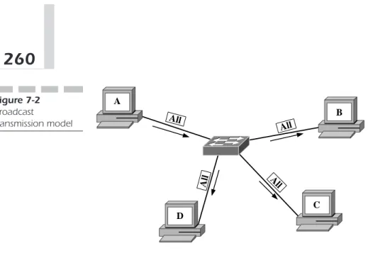
A B C D All All A ll All Figure 7-2 Broadcast transmission model
Figure 7-2). Broadcasting is simply one host transmitting to all hosts. In the case of Ethernet, broadcast traffic is bound to all the hosts in a broadcast domain. In IP, a broadcast is bound to an IP subnet.
As we have seen, broadcasting can cause problems due to its global nature. Because all broadcast packets are sent to all hosts, probably not all the hosts need to receive the packet. This global transmission can lead to unnecessary traffic.
An example of broadcasting is the Address Resolution Protocol (ARP) request. ARPs are sent to all hosts to find a host that knows the MAC address associated with a particular IP address. More than one host may have the information, but in other cases only one may have it. This situation requires the use of the broadcast transmission model.
Multicast Transmission
Multicasting is similar to broadcasting in that there is a one-to-many traf-fic pattern. The difference is the receiving hosts are a subset of all the hosts. Already, we can see that multicasting can increase the efficiency of the net-work by reducing the amount of unnecessary netnet-work traffic.
Creating many unicast streams can mimic multicasting (see Figure 7-3). Each of these streams will have the same originating host and each stream will terminate to a different host in the multicast group. However, using many unicast streams to implement one multicast stream is inefficient across a large internetwork.
A B C D M M M M Figure 7-4
One multicast stream
A B C D C D B B C D Figure 7-3
Many unicast streams
If many unicast streams originate from the same source and each termi-nates to a different user and carries the same traffic, the intermediate links could be burdened with lots of redundant traffic. The solution is to create a group of hosts and an addressing scheme for the group and let the network decide how to replicate the source stream to all receivers. The traffic stream will then be addressed to the multicast address (see Figure 7-4). The net-work is left to decide how to organize traffic over its links to best utilize available bandwidth.
Multicasting can be deployed for a number of applications. The most obvious application is video transmission over the campus network. In this case, the same traffic is sent from one source to many hosts. Video traffic
can be very bandwidth-intensive. Duplicating the traffic to many hosts can be detrimental to a network, if not impossible. Multicasting helps alleviate this problem by having the source send one stream to a multicast group address and let the network decide what links should carry the multicast traffic.
Multicast Addressing
Multicast addressing involves both Layer 2 and Layer 3 addressing. The IP layer specifies the IP multicast group address. The Layer 2 MAC address is changed according to the Layer 3 IP multicast address. The Layer 2 MAC addresses are derived from the Layer 3 multicast address so multicast ARPs are not needed.
Note that implementing multicast ARP could be a horrendous task. Imagine if a multicast group address exists and a host needs to send a packet to the multicast group. After the IP header is addressed with the IP multicast address as the destination IP addresses, the host needs to deter-mine the MAC addresses of all the hosts in the multicast group. In most cases, this would be nearly impossible because the multicast address can span multiple broadcast domains. Therefore this imaginary multicast ARP would have to trasverse all subnets, VLANs, and broadcast domains. After multicast becomes a staple for a campus network, the network could come to a standstill just from a multicast ARP transaction using this method.
Both Layer 3 and Layer 2 multicast addressing is discussed in the fol-lowing sections.
IP Multicast Addressing
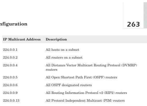
Multicast IP addressing uses class D IP addresses. Recall from Chapter 6, “Unicast Layer 3 Configuration,” that class D addresses start with the bit pattern 1110. Therefore, the first four bits of an IP multicast address are fixed. The following 28 bits of the IP multicast address can be anything, so the range of IP multicast addresses starts with 224.0.0.0 and ends with 239.255.255.255. The bit pattern of the IP multicast following the initial byte has no structure. There are some well-known IP multicast addresses, however. The Internet Assigned Numbers Authority (IANA) defines these well-known IP multicast addresses. Table 7-1 lists a few.
Table 7-1
Well-known IP multicast addresses
IP Multicast Address Description
224.0.0.1 All hosts on a subnet
224.0.0.2 All routers on a subnet
224.0.0.4 All Distance Vector Multicast Routing Protocol (DVMRP) routers
224.0.0.5 All Open Shortest Path First (OSPF) routers
224.0.0.6 All OSPF designated routers
224.0.0.9 All Routing Information Protocol v2 (RIP2) routers 224.0.0.13 All Protocol Independent Multicast (PIM) routers
Ethernet Multicast Addressing
Ethernet multicast addressing is a little trickier. As discussed previously, the Layer 2 multicast MAC address is derived from the Layer 3 IP multi-cast address. The process is as follows.
IANA has defined that all Ethernet multicast addresses always begin with the hex values “01 00 5E” in the first three bytes. The next bit of the address is “0.” That takes care of 25 of the 48 bits in the Ethernet MAC address (see Figure 7-5). The remaining 23 bits are derived from the lowest order 23 bits from the IP Multicast address.
Here is an example of how this Ethernet multicast-addressing scheme works. For the multicast address 224.0.1.1, the resulting Ethernet MAC address is derived as follows.
The lowest 23 bits of the IP multicast address are as follows.
Because all multicast Ethernet MAC addresses always begin with (01-00-5e)16, this defines the Ethernet Multicast address as
100000001000000000101111000000000000000010000000122 10000000.00000001.0000000122
224 E0 1110 0000 01 0000 0001 01 0000 0001 65 41 0100 0001 00 0000 0000 00 0000 0000 10 0A 0000 1010 5E 0101 1110 5E 0101 1110 00 0000 0000 0A 0000 1010 00 0000 0000 9A 1001 1010 0 154 9A 1001 1010 00 0000 0000 41 100 0001
8
8
32 bits
32 bits
16
16
48 bits
48 bits
16
Figure 7-5 IP multicast to Ethernet MAC address mappingNote that because 23 bits of a 32-bit IP multicast address are mapped to a MAC multicast address, a chance exists that two different IP multicast groups can have the same multicast MAC address.
For example, map the following IP Multicast addresses to multicast MAC addresses: 224.1.1.1 and 225.1.1.1.
For the case of 224.1.1.1:
The resulting multicast MAC address is
or
For the case of 225.1.1.1:
The resulting multicast MAC address is
or .101005e010101216 100000001000000000101111000000001000000010000000122 1225.1.1.1210 111100001.00000001.00000001.0000000122 101005e010101216. 100000001000000000101111000000001000000010000000122 1224.1.1.1210111100000.00000001.00000001.0000000122
Both of the MAC addresses are identical for different IP multicast addresses.
Note that applications typically use UDP port numbers in multicasting to distinguish what stream belongs to a particular application on a host. A host would not be able to distinguish two multicast streams with identical destination MAC addresses and identical UDP port addresses. Fortunately, this is an unlikely case.
Multicast Group Management
Multicast traffic management works by forwarding multicast traffic onto a particular port if at least one device on the port is a member of the multi-cast group to which the multimulti-cast traffic corresponds. If no hosts connected to a port are members of that particular multicast group, no multicast pack-ets are forwarded to that port for that group.
If more than one host on a port is a member of a particular multicast group, all the hosts will receive the multicast group traffic because all the hosts have the same multicast MAC address.
This operation makes group management a necessity. This section describes three mechanisms for managing multicast group management. These mechanisms are as follows:
■ Internet Group Management Protocol, Version 1 (IGMPv1)
■ Internet Group Management Protocol, Version 2 (IGMPv2)
■ Cisco Group Management Protocol (CGMP)
Internet Group Management Protocol
Version 1 (IGMPv1)
IGMPv1 is encapsulated in an IP packet with a protocol identifier of 2.
IGMP Version 1 Packet Format The packet format for IGMP Version 1 is shown in Figure 7-6.
The version field is a four-bit value that is always set to 1 because the version 2 packet format is different.
Version Type Unused Checksum Group Address
8
8
8
8
32 bits
32 bits
Figure 7-6 IGMP version 1 packet format Table 7-2 IGMP v1 type field values Value Description1 Host Membership Query
2 Host Membership Report
The Type field is a four-bit field that specifies the type of IGMP message the packet represents. The valid values for this field are shown in the Table 7-2.
The next byte of the IGMPv1 packet is unused and set to all zeros. The receiver ignores this field.
The checksum field is two bytes long and is a 16-bit complement of the entire IGMPv1 message.
The Group Address field holds a four-byte IP multicast address of the multicast group that a host is a member of. The use of this field is explained in more detail later. This field is used for a Host Membership Report only. This field is set to all zeros if the packet is a Host Membership Query message.
IGMPv1 Operation The operation of IGMPv1 is very simple. The router sends Host Membership Queries and the hosts respond with Host Mem-bership Reports. The idea is for the router to keep up with what group traf-fic must be forwarded to each of its interfaces. The following discussion describes the details of IGMPv1 operation.
A router sends an IGMP Host Membership Query to determine the group membership information for all the multicasting hosts on each of its interfaces. If any host responds, the router must send all traffic for that group to the interface. IGMP Host Membership Queries are sent to an IP
multicast address of 224.0.0.1, which is the All Hosts well-known IP multi-cast address. The TTL value in the IP header is set to 1.
The host responds with one or more Host Membership Report packets to let the router know what groups it is a member of. The host places the mul-ticast group address of the group it has joined in the Group Address field in the IGMPv1 packet.
Close examination shows us that this type of operation could cause a flooding problem. When the router sends a Host Membership Query, all multicast enabled hosts can respond to the query with a Host Membership Report packet for each group of which the host is a member.
Multicast hosts do two things to diminish the effects of Host Membership Report flooding:
■ Implement a Host Membership Report timer
■ Implement a selective Host Membership Report scheme
A Host Membership Report timer is used to reduce the frequency of the reports from a particular multicast host. This timer can be configurable by the user.
Because the router only needs to know that one host is a member of a particular group for an interface, the router doesn’t need to see multiple Host Membership Reports for any multicast group. To reduce the occur-rence of multiple Host Membership Reports, the hosts can implement the Host Membership Timer and listen for Host Membership Reports for other hosts on the network that are members of the same groups. If the host sees a Multicast Host Membership Report from another host that is a member of the same group, the host no longer needs to send the report. If all multi-cast hosts implement the Host Membership Timer, the amount of band-width consumed with Host Membership Report packets is greatly reduced.
IGMPv1 States Figure 7-7 shows the state diagram of a multicast host with IGMPv1 enabled.
Three states for each IGMPv1 multicast host are in each multicast group: ■ Non-member
■ Delaying member ■ Idle member
A host in the non-member State is not a member of the particular mul-ticast group.
DELA
DELAYING
YING
MEMBER
MEMBER
NON-MEMBER
MEMBER
IDLE
IDLE
MEMBER
MEMBER
leave group leave group
join group query recvd report recvd timer expired query recvd Figure 7-7 IGMPv1 state
A host in the Delaying Member State has received a Host Membership Query from the router and has started its Host Membership timer. The host will not send the Host Membership Report until its Host Membership timer has expired.
A host enters the Idle State when the Host Membership Report is sent or it has seen a Host Membership Query from another host.
The following events cause the host’s transition between states: ■ A host joins a group
■ A host leaves a group
■ A Host Membership Query is received
■ A Host Membership Report is received from another host ■ The Host Membership timer expires
Joining and Leaving Multicast Groups A host joins a multicast group by simply sending a Host Membership Report message. The host does not need to wait for a Host Membership Query from the router.
A host leaves a group by not sending any Host Membership Reports. The router knows to stop forwarding packets to a group when no more Host
Membership Reports are received in response to its Host Membership Queries.
Configuring IGMPv1 To enable IGMP on a router, use the following global Cisco IOS command:
Router(config)# ip multicast-routing
By default the router will then enable IGMPv2 on all interfaces. To spec-ify IGMPv1, enter the following interface sub-command:
Router(config-int)# ip igmp version 1
To verify the IGMP version on a particular interface, enter the following:
Router# show ip igmp interface [interface]
Without specifying a particular interface, it will display information for all interfaces. To verify proper IGMP operation after you have hosts attached, you may view the requested groups using the following:
Router# show ip igmp groups
Now that you have an active router sending Host Membership Queries, you must enable IGMP on your switches to keep multicast under control on each network segment.
To enable IGMP on a Set-Command based switch, use the following:
Switch(enable) set igmp enable
To turn off IGMP, use the disable form of the command.
Switch(enable) set igmp disable
To verify operation, enter the following:
Note that switches using Cisco IOS do not include IGMP operation. With an understanding of IGMPv1, let us look at the improvements in Version 2.
Internet Group Management Protocol
Version 2 (IGMPv2)
IGMPv2 is fully specified in RFC 2236.
IGMPv2 Packet Format Figure 7-8 shows the packet format for an IGMPv2 packet. The format is very similar to the IGMPv1 packet format. The type field represents the type of IGMPv2 message. Table 7-3 lists the possible values.
The Membership Query message can be either a general query or a group-specific query. The general query is used to determine which groups have active members. The group-specific query is used to determine if a par-ticular multicast group has active members. The group address field is the way to distinguish between a general query and a specific query. A general
Type Max RTime Checksum
Group Address
8
8
8
8
32 bits
Figure 7-8 IGMPv2 packet format Table 7-3IGMPv2 type field values
Type Field Value Description
0x11 Membership Query
0x16 Version 2 Membership Report
0x17 Leave Group
query will have zeros in the group address field and the group-specific query will have a valid IP multicast address.
The Max RTime is an eight-bit field that specifies the maximum amount of time a host can wait before responding to a Membership Query message. This field is only applicable to Membership Query messages. The Maximum Response time is represented in tenths of seconds.
The checksum field is identical to the two-byte checksum field in an IGMPv1 packet. The checksum is a 16-bit complement of the entire IGMPv2 message.
The Group Address is a four-byte IP multicast address.
The Querier Router IGMPv2 handles the case of multiple routers on a multiple access network. All routers begin in a querier state. Routers will transition from a querier state to a non-querier state when they receive a membership query from another router with a lower IP address. Therefore, only one router eventually remains in the querier state. This router has the lowest IP address of all the multicast routers on the network.
IGMPv2 also handles the situation when the querier router fails. The non-querier routers maintain an Other Querier Present Interval timer. This timer is reset every time the router receives a Membership Query message. If the timer expires, the router begins sending Query messages and the querier router elections begin.
The querier router must send periodic Membership Query requests to make sure that other routers on the network understand that the querier router is still operational. To do this, the querier router maintains a Query Interval timer. This timer is reset when a Membership Query message is sent. When the Query Interval Timer reaches zero or out of necessity, the querier router sends another Membership Query.
Multicast Router Initialization When the router first comes up, it sends a number of General Query messages to see which multicast groups should be forwarded on a particular interface. The number of General query messages a router sends is based on the Startup Query Count value con-figured in the router. The amount of time between the initial General Query messages is defined by the Startup Query Interval value.
IGMPv2 Host Operation The host sets a delay timer when a General Query message is received. This value is set to a random number between
1 and the Maximum Response Time for each multicast group of which the host is a member. When any of these delay timers reach zero before the host receives a Membership Report for any of its groups, the host sends a Mem-bership Query report.
If the host receives a Membership Report, the delay timer for that group is reset and the Membership Report is canceled. When the host receives a Membership Query for a group that has a delay timer that hasn’t expired, the host will reset the timer only if the time remaining on the delay timer is greater than the Maximum Response Time in the Membership Query packet.
Joining and Leaving a Multicast Group When a host intends to join a multicast group, it sends a Membership Report for the group it wants to join. The host waits a predetermined amount of time and sends another Membership Report. The host sends two Membership Reports to lessen the possibility of the Membership Report not making it to the router. The length of time between the Membership Reports is called the Unsolicited Report Interval.
To leave a group, the host that sent the last Membership Report for a group sends a leave message to the all router multicast address, 224.0.0.2. If a host intends to leave a group, but wasn’t the last host to send a Member-ship Report for the group, it is not necessary for the host to send a leave mes-sage. In either case, a host can send a leave mesmes-sage. The use of the leave message in IGMPv2 is different than in IGMPv1 where the group eventually times out.
When the querier router receives a leave message, it must send a Group-Specific Membership Query to find out if the host is the last to leave the group. The router sends a number of these messages before stop-ping to forward packets for that group. This number is equal to the Last Member Query Count. The router sends more than one Group-Specific Membership Query to make sure there are no more members in that group. These queries are sent every Last Member Query Interval seconds to pace the queries. When no responses are received for the queries, the router stops forwarding multicast traffic for this group address on that particular interface.
IGMPv2 Timers Table 7-4 summarizes the timers and counters dis-cussed above in describing IGMPv2 operation.
Table 7-4
IGMPv2 timers and counters
Variable Default Value
Query Interval (QI) 125 seconds
Query Response Interval (QRI) 10 seconds
Startup Query Interval 0.25(Query Interval)=31 seconds Startup Query Count (SQC) 2
Other Querier Present Interval (SQC*QI)+QRI/2=255 seconds Group Membership Interval (SQC*QI)+QRI=260 seconds Last Member Query Interval 1 second
Last Member Query Count SQC
Unsolicited Report Interval 10 seconds Version 1 Router Preset Timeout 400 seconds
IGMPv2 State Diagrams Figure 7-9 illustrates the host state diagram for IGMPv2.
Note that the host can be in one of three states—Non-Member, Delaying Member, or Idle Member. This state diagram is kept for all groups. A host in a Non-Member State is not a member of the multicast group. A host in the Delaying Member State has just tried to join the multicast group. A host in the Idle Member State has either an expired timer or has received a Mem-bership Report for the group from another host. If a query is received for the group, the host returns to the Delaying Member State.
Multicast hosts keep up with the version of IGMP routers on the net-work according to Figure 7-10.
Figure 7-11 summarizes the querier router election process.
The router can be either a querier router or a non-querier router (see Fig-ures 7-12 and 7-13).
Configuring IGMPv2 To enable IGMP on a router, use the following global Cisco IOS command:
DELA
DELAYING
YING
MEMBER
MEMBER
NON-MEMBER
MEMBER
IDLE
IDLE
MEMBER
MEMBER
leave group leave group
join group query recvd report recvd timer expired query recvd Figure 7-9 IGMPv2 host state
IGMPv1 Query Recvd timer expires
IGMPv1
IGMPv1
ROUTER
OUTER
PRESENT
PRESENT
NO IGMPv1
NO IGMPv1
ROUTER
OUTER
PRESENT
PRESENT
IGMPv1 Query Recvd Figure 7-10 IGMPv1 and IGMPv2 interoperability stateBy default, the router will then enable IGMPv2 on all interfaces. However, if you need to specify IGMPv2, enter the following interface sub-command:
Router(config-int)# ip igmp version 2
To verify the IGMP version on a particular interface, enter the following:
leave group leave group leave recvd v2 report recvd v1 report recvd v2 report recvd v1 report recvd
v1 report recvd timer expired
timer expired v1 report recvd Members Present No Members Present Checking Member-ship v1 report recvd v2 report recvd v2 report recvd retransmit timer expired Version 1 Members Present v1 host timer expired Figure 7-12 Querier router state
send general query set timer
INITIAL
INITIAL
STATE
TE
NON-QUERIER
UERIER
QUERIER
UERIER
query recvd from router with lower IP
address set other querier
present timer
other querier timre expired send general query
set timer
query recvd from router with lower IP
address set other querier
present timer
Figure 7-11 Querier and non-querier router state
timer expired timer expired report recvd report recvd g-s query recvd report recvd
MEMBERS
MEMBERS
PRESENT
PRESENT
NO
NO
MEMBERS
MEMBERS
PRESENT
PRESENT
CHECKING
CHECKING
MEMBERSHIP
MEMBERSHIP
Figure 7-13 Non-querier router stateThe following shows an example output of the command. You can see the status and version information.
Router#show ip igmp interface Vlan1 is up, line protocol is up
Internet address is 100.1.1.7/24 IGMP is enabled on interface Current IGMP version is 2 CGMP is enabled on interface IGMP query interval is 60 seconds IGMP querier timeout is 120 seconds IGMP max query response time is 10 seconds Inbound IGMP access group is not set IGMP activity: 19 joins, 13 leaves Multicast routing is enabled on interface Multicast TTL threshold is 0
Multicast designated router (DR) is 100.1.1.233 IGMP querying router is 100.1.1.1
Multicast groups joined (number of users):
224.2.127.254(1) 239.255.255.255(1) 224.0.1.40(1)
Without specifying a particular interface, it will display information for all interfaces. To verify proper IGMP operation after you have hosts attached, you may view the requested groups using the following:
The following shows an example output from the command:
Router# show ip igmp groups IGMP Connected Group Membership
Group Address Interface Uptime Expires Last Reporter 239.255.255.255 Vlan1 3d20h never 100.1.1.7 239.255.255.253 Vlan116 21:41:44 00:02:47 100.1.121.125 239.255.255.253 Vlan114 2d19h 00:02:08 100.1.11.71 239.255.255.253 Vlan109 3d20h 00:02:45 100.1.76.22 224.2.127.255 Vlan113 3d20h 00:02:51 100.1.193.55
Now that you have an active router sending Host Membership Queries, you must enable IGMP on your switches to keep multicast under control on each network segment.
To enable IGMP on a Set-Command based switch, use the following:
Switch(enable) set igmp enable
To turn off IGMP, use the disableform of the command.
Switch(enable) set igmp disable
To verify operation, enter the following:
Switch(enable) show igmp statistics [vlan_id]
For IGMPv2, you can also enable fastleave. This feature, when enabled, decreases the delay between receiving a Leave Group packet and disabling forwarding of multicast to the port for that specific group. The default timer value is the Group Membership Interval (default, 260 sec-onds). Enabling IGMP fastleave reduces this value to the Query Response Interval (default 10 seconds). This works based on the assump-tion that the querier router will send a Group-Specific Membership Query when a Leave Group packet is received from a host. The Group-Specific Membership Query would force other hosts receiving that group to respond with a Membership Report packet. If a Membership Report packet is received for the same group the Leave Group packet specified, multicast for that group is not interrupted. If the timer expires, traffic is no longer for-warded to the port for the specified multicast group.
IGMP is supported, although not in the Catalyst 1900 series. Cisco Sys-tems’ CGMP is their multicast management protocol of choice and is fully supported across the entire product line.
Cisco Group Management Protocol (CGMP)
CGMP Overview So far, we have covered how a host can communicate with a router to enable a multicast flow onto the host’s broadcast domain. As mentioned before, the router needs to know only that one host on an interface needs traffic from a particular multicast group to turn on multi-cast traffic for that group. IGMPv1 and IGMPv2 both handle the commu-nication between the host and the router to turn on this multicast flow.Let’s look a little deeper into the multicast network. A host wants to join a multicast group and uses IGMPv2 to let the router know that it needs that particular multicast traffic. The router begins to forward the multicast traffic onto the same interface to which the host is connected. Note that the broadcast domain to which the router’s interface is connected is flooded with the multicast group’s traffic. Every host in the broadcast domain sees the traffic because all the switches in the broadcast domain know to flood packets to all ports that are destined for a multicast MAC address.
This is not an ideal situation. It would be better if there was a way to let the switches know what interfaces need to forward multicast traffic. The
Cisco Group Management Protocol (CGMP) provides this functionality.
Note that CGMP is a Cisco proprietary protocol and it does not interoper-ate with other vendors’ switches.
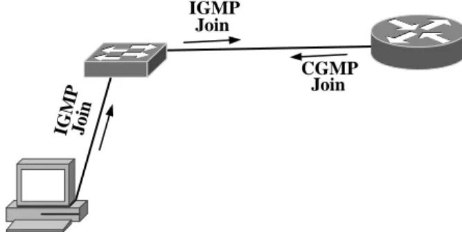
Figure 7-14 shows the interaction between IGMP and CGMP.
IG M P Join IGMP Join CGMP Join Figure 7-14 IGMP and CGMP interaction
8
8
8
8
Version Type Reserved Count
GDA USA USA GDA
32 bits
32 bits
Figure 7-15 CGMP packet formatThe hosts send IGMP messages that the routers receive and process. The routers in turn communicate with the Layer 2 switches on the net-work via CGMP. This communication between the routers and switches gives the switches the information they need to know to forward multicast traffic.
CGMP Packet Format Figure 7-15 shows the CGMP packet format. The version field is a four-bit field that gives the CGMP version number. CGMP has only one version. This field always has a 0x1 value.
The type field is a four-bit field that describes the CGMP message type. The valid values are 0x0 for Join or 0x1 for Leave.
The reserved field is 16 bits long and is set to all zeros. This field is not currently used.
The count field is an eight-bit field that gives the number of group desti-nation address and unicast source address pairs in the rest of the message. The Group Destination Address (GDA) field is six bytes long. It holds the multicast group destination address.
The Unicast Source Address (USA) field is a 6-byte field that contains the MAC address of a host.
CGMP Operation The router sends a CGMP Join message to the switches on the network to let them know which of their ports is connected to the router. The CGMP packet is formatted as a Join message with the GDA as all zeros and the USA as the router’s MAC address.
To notify all the switches that a particular group is no longer active, the router sends a Leave message to the switches with the GDA of the inactive group and the USA field all zeros. The switches then know to delete all the
entries associated with that particular group. If no groups are active, the router sends a Leave message with both the GDA and USA fields set to zero. When a switch receives an all-group leave packet, the switch begins flooding all multicast traffic as if CGMP is disabled.
After a router receives an IGMP join message, it then sends a CGMP Join message to the switches on the same interface. The switches respond by setting their forwarding tables appropriately to only forward multicast traffic for the group listed in the CGMP message to the host listed in the CGMP message. IGMPv2 leave messages received by the router are fol-lowed by CGMP leave messages from the router to the switches.
Configuring CGMP To enable CGMP on a router, you use the following global Cisco IOS command:
Router(config)# ip multicast-routing
By default, the router will then enable IGMPv2 on all interfaces. In addi-tion to IGMP, you must also specifically enable CGMP. To enable CGMP, enter the following interface sub-command.
Router(config-int)# ip cgmp
To verify CGMP operation on a particular interface, enter the following:
Router# show ip igmp interface [interface]
Without specifying a particular interface, it will display information for all interfaces. To verify proper IGMP operation after you have hosts attached, you may view the requested groups using the following:
Router# show ip igmp groups
Now that you have an active router sending IGMP Host Membership Queries and sending CGMP Join messages on the network, you must enable CGMP on your switches to keep multicast under control on each net-work segment.
To enable CGMP on a Set-Command based switch, use the following:
On a switch, you may only enable IGMP or CGMP, not both. To turn off CGMP, use the disableform of the command.
Switch(enable) set cgmp disable
To verify operation, enter the following:
Switch(enable) show cgmp statistics [vlan_id]
For CGMP, you can also enable IGMPv2 leave processing. This feature, when enabled, decreases the delay between receiving a Leave Group packet and disabling forwarding of multicast to the port for that specific group. When a Leave Group packet is received, the switch sets a Query Response timer (default 10 seconds). If the timer expires before receiving a CGMP Join message, traffic is no longer forwarded to the port for the specified mul-ticast group. By default, with IGMPv2 leave processing disabled, the switch will wait for the CGMP Hold Timer to expire (default 300 seconds) before halting multicast traffic forwarding to the port.
Switch(enable) set cgmp leave {enable | disable}
To view CGMP leave statistical information, use the command
Switch(enable) show cgmp leave
To enable CGMP on Cisco IOS-based devices, you would use the follow-ing global command:
Switch(config)# cgmp
To verify CGMP operation, use the following command:
Switch# show cgmp
Chapter Summary
As we have seen in this chapter, multicast traffic management is quite dif-ferent from unicast traffic management. IP multicast addressing spans the entire Internet and can not be subnetted like unicast IP addressing.
IGMPv1, IGMPv2, and CGMP exist simply to manage the flow of multicast traffic into and within a broadcast domain because unbridled multicast traffic can bring a campus network to its knees.
In summary, the following topics were covered in this chapter: ■ Multicast traffic overview
■ IP Multicast Addressing
■ Internet Group Management Protocol Version 1 (IGMPv1)
■ Internet Group Management Protocol Version 2 (IGMPv2)
■ Cisco Group Management Protocol (CGMP)
Multicast is an important type of traffic in the campus network. Multi-cast traffic can be achieved by having multiple uniMulti-cast streams in the net-work, but the redundant packets are an inefficient use of bandwidth. Multicast traffic provides a mechanism for one host to send one stream to multiple destinations.
IP multicast addressing uses the class D IP address space. All the add-resses are in one subnet. In other words, there is no concept of a subnet mask in IP multicasting. An IP multicast address represents a group of des-tination hosts. The multicast MAC addresses are generated by mapping part of the IP multicast address into part of the MAC address and vice versa.
IGMPv1 and IGMPv2 exist to restrict the flow of multicast traffic to broadcast domains that need the multicast traffic. This goes a long way to thin out unneeded multicast traffic to optimize the use of bandwidth. These protocols operate between the hosts and their routers on the network.
CGMP exists to restrict the flow of multicast traffic within a broadcast domain. This helps restrict multicast traffic to only be forwarded to the Layer 2 switch ports that need multicast traffic. CGMP operates between the router and the switches in a broadcast domain.
At this point, you are equipped to implement IP multicasting in your broadcast domains on your campus network. You are able to efficiently manage the multicast traffic throughout the broadcast domains in your campus network to make good use of available bandwidth.
When you review and thoroughly understand the concepts of IP multi-casting and how to apply them to the broadcast domains in your campus network, you are ready to move on to managing the multicast traffic between your broadcast domains with IP multicast routing. These princi-ples will allow you to efficiently route and manage IP multicast streams throughout your entire campus network.
Frequently Asked Questions (FAQ)
Question: Why is there no “multicast ARP” mechanism?
Answer: On the surface, it would make sense to design a protocol
to resolve a multicast address to the MAC addresses associated with it. Because multicast groups can span the Internet, one simple “multicast ARP” could be flooded to all Internet connected hosts. The other problem is how to cache the potentially large number of MAC addresses that could be members of a particular multicast group. Therefore, a “multicast ARP” mechanism isn’t feasible.
Question: How do other vendors typically manage multicast on the
network?
Answer: Other vendors implement IGMP on the switch and the
router. When a host sources an IGMP request, the router uses the IGMP request to start forwarding multicast packets for the group. The switch uses the request to set a filter for the port to allow only the requested multicast group traffic to that port.
Case Study
Objective: CPI management has decided to build a video conferencing sys-tem to allow employees to meet without having to constantly move from one building to another. Studies have shown that CPI managers consume countless hours traveling between meetings across CPI’s large campus.
You are to prepare for the coming application by implementing IP mul-ticast traffic management in each of the VLANs before mulmul-ticast traffic is turned on across the entire campus network.
Approach
The following tasks must be completed to achieve your objective: ■ Decide where multicast traffic will be used throughout the campus
network
■ Decide how to handle multicast traffic within the broadcast domains in CPI’s network
■ Implement your multicast traffic management design within the CPI campus network
Where Is Multicast Traffic Needed?
Multicast will be required on the Administrative, Information Technologies, and Research and Development VLANs. The employees of those depart-ments spend the most time going to meetings.
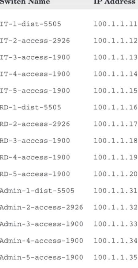
Table 7-5 shows the VLAN identifiers that are in place. Table 7-6 lists the device names and their IP addresses.
Multicast Traffic Management in the
Broadcast Domains
For each VLAN, a multicast management protocol is required to prevent multicast traffic from disturbing other users. Because our network is com-prised entirely of Cisco Systems equipment, we will implement CGMP.
Table 7-6
Switch names and IP addresses
Switch Name IP Address
IT-1-dist-5505 100.1.1.11 IT-2-access-2926 100.1.1.12 IT-3-access-1900 100.1.1.13 IT-4-access-1900 100.1.1.14 IT-5-access-1900 100.1.1.15 RD-1-dist-5505 100.1.1.16 RD-2-access-2926 100.1.1.17 RD-3-access-1900 100.1.1.18 RD-4-access-1900 100.1.1.19 RD-5-access-1900 100.1.1.20 Admin-1-dist-5505 100.1.1.31 Admin-2-access-2926 100.1.1.32 Admin-3-access-1900 100.1.1.33 Admin-4-access-1900 100.1.1.34 Admin-5-access-1900 100.1.1.35 Table 7-5
VLANs and their identifiers VLAN VLAN ID Management R&D 1 Mfg 2 SR 3 Admin 4 IT 5
Implementing Multicast Traffic Management
in the Broadcast Domains
Implementation will begin with enabling CGMP on the routers. First, the Administrative router:
Admin-1-dist-5505(config)# ip multicast-routing Admin-1-dist-5505(config)# interface Vlan4 Admin-1-dist-5505(config-if)# ip cgmp
Repeat for the Information Technologies and Research and Development routers, substituting the appropriate VLAN identifier.
IT-1-dist-5505(config)# ip multicast-routing IT-1-dist-5505(config)# interface Vlan5 IT-1-dist-5505(config-if)# ip cgmp
RD-1-dist-5505(config)# ip multicast-routing RD-1-dist-5505(config)# interface Vlan1 RD-1-dist-5505(config-if)# ip cgmp
Next, CGMP must be enabled on all access layer switches. For the Catalyst 2926 series, use the following commands:
Admin-2-access-2926(enable) set cgmp enable
Also, enable CGMP leave processing:
Admin-2-access-2926(enable) set cgmp leave enable
Repeat for the other Catalyst 2926 switches.
For the Catalyst 1900’s, enter the following command:
Admin-3-access-1900(config)# cgmp
Repeat for the rest of the Catalyst 1900s. Recall that the Catalyst 1900 does not support CGMP leave processing.
Case Study Summary
The CPI campus network now supports multicast applications on the Administrative, Information Technologies, and Research and Development VLANs. Now those departments may utilize video conference software to
help minimize travel requirements to attend meetings. This will help save money by cutting staff down time.
The following steps were completed to get to this point. We started with an optimal Layer 2 and Layer 3 configuration and then
■ Defined where multicast traffic will be used throughout the campus network
■ Defined protocol to be used to handle multicast traffic within the broadcast domains in CPI’s network
■ Implemented multicast traffic management design within the CPI campus network
CPI’s network is now configured to handle multicast traffic within the three VLANs in an optimal fashion. Later chapters will explore how to implement routing features optimized for multicast transmission.
Questions
1. _____________ can be used to implement IP multicast transmissions. a. unicast
b. multicast c. broadcast
d. none of the above
2. The IP multicast address 236.43.5.1 is translated to which of the
following Ethernet MAC addresses?
a. 01-00-5e-43-05-01 b. 01-00-5e-2b-05-01 c. 00-00-5e-2b-05-01 d. none of the above
3. The IP address 224.43.5.1 is translated to which of the following
Ethernet MAC addresses?
a. 01-00-5e-43-05-01 b. 01-00-5e-2b-05-01 c. 00-00-5e-2b-05-01 d. none of the above
4. Using the conventional Ethernet MAC to IP multicast address
mappings, the resulting multicast addresses are _________________.
a. unique b. not unique c. inverted d. six bytes long
5. IGMPv1 is not supported on the Catalyst ________. a. 2926
b. 5505 c. 1900 d. 6513
6. IGMPv2 is not supported on the Catalyst ________. a. 2926
b. 5505 c. 1900 d. 6513
7. IGMP is a _____________ ______________ protocol. a. group management
b. host management c. multicast routing d. Internet routing
8. IGMPv2 is IGMPv1 with the addition of __________________. a. leave-support
b. one c. routing d. CGMP
9. IGMPv2 can support _______ querier routers. a. 10
b. 125 c. 400 d. infinite
10. Which of the following does not describe a multicast application? a. one sender, many receivers
b. many senders, many receivers c. video conference d. telephone 11. CGMP was developed by ____________ ______________. a. 3Com Corporation b. Cisco Systems c. Nortel Networks d. CG and MP 12. CGMP is a replacement for a. IGMPv1 b. IGMPv2 c. Both a and b d. Neither a or b
13. CGMP defines communication between a. hosts and switches
b. hosts and routers c. switches and routers d. switches and switches
14. Using Cisco IOS,ip multicast-routingmust be enabled for
a. IGMPv1 b. IGMPv2 c. CGMP d. all the above
15. With cgmpand cgmp leaveenabled on a switch and ip cgmpenabled on a router, which device(s) receive and process IGMP requests?
a. both switch and router b. only router
c. neither switch nor router d. only switch
16. When configured for IGMPv2 operation, a router will also listen for
____________ packets.
a. SDR b. CGMP c. NTP d. IGMPv1
17. CGMP consists of two types of packets: a. request/reply
b. send/receive c. join/leave d. forward/reply
18. The all router IP multicast address is _______________. a. 224.0.0.1
b. 224.0.0.2 c. 224.0.0.3 d. 239.255.255.255
19. IGMPv2 handles multiple routers on a single network by designating a
___________ router.
a. querier b. standby c. active d. default
20. CGMP uses ______________ to communicate multicast group
joins/leaves between routers and switches.
a. unicast b. multicast c. broadcast d. simulcast
Answers
1. _____________ can be used to implement multicast transmissions. a. unicast
Multicast transmissions can be implemented with many unicast streams. This is not recommended because sending multiple unicast streams is less efficient than one multicast stream.
2. The IP address 236.43.5.1 is translated to which of the following
Ethernet MAC addresses?
b. 01-00-5e-2b-05-01
All Ethernet MAC address begin with 01-00-5e and a “0” in the next bit position. The last 23 bits of the MAC address are the last 23 bits of the multicast IP address.
3. The IP address 224.43.5.1 is translated to which of the following
Ethernet MAC addresses?
b. 01-00-5e-2b-05-01
All Ethernet MAC address begin with 01-00-5e and a “0” in the next bit position. The last 23 bits of the MAC address are the last 23 bits of the multicast IP address.
4. Using the conventional Ethernet MAC to IP multicast address
mappings, the resulting multicast addresses are _________________.
b. not unique
Because the last 23 bits of the multicast IP address are used for the MAC address, this address mapping technique between multicast IP and multicast Ethernet MAC addresses is not a one-to-one mapping.
5. IGMPv1 is not supported on the Catalyst ________. c. 1900
6. IGMPv2 is not supported on the Catalyst ________. c. 1900
7. IGMP is a _____________ ______________ protocol. a. group management
8. IGMPv2 is IGMPv1 with the addition of __________________. a. leave-support
9. IGMPv2 can support _______ querier routers. d. infinite
10. Which of the following does not describe a multicast application? d. telephone
A telephone call is a one-to-one (point-to-point) connection. A multicast transmission is a one-to-many transmission.
11. CGMP was developed by ____________ ______________. b. Cisco systems
12. CGMP is a replacement for
c. Both a and b (IGMPv1 and IGMPv2)
13. CGMP defines communication between c. switches and routers
IGMP acts as a mechanism to handle multicast group maintenance. With IGMP, hosts communicate group maintenance information to routers. CGMP is a protocol to communicate the group maintenance information to switches in Layer 2 networks.
14. Using Cisco IOS,IP multicast-routingmust be enabled for
d. all of the above IGMPv1, IGMPv2, CGMP
15. With CGMPand CGMPleave enabled on a switch and IP CGMP enabled on a router, which device(s) receive and process IGMP requests?
a. both switch and router
16. When configured for IGMPv2 operation, a router will also listen for
____________ packets.
d. IGMPv1
IGMPv2 is backwardly compatible with IGMPv1
17. CGMP consists of two types of packets: c. Join/Leave
18. The all router IP multicast address is _______________. b. 224.0.0.2
19. IGMPv2 handles multiple routers on a single network by designating a
___________ router.
a. querier
20. CGMP uses ______________ to communicate multicast group joins/
leaves between routers and switches.