Step by Step:
Ethernet Communication
between OPC Server and
S7-200 incl. CP243-1
Manual
Contents
Overview and
Environment
1
Configuration and
Programming
2
Download and
Commissioning
3
Operator Control and
Monitoring
4
Copyright Siemens AG, 1998 to 2003, All rights reserved
The reproduction, transmission or use of this document or its contents is
Disclaimer
We have checked the contents of this manual for agreement with the
notices are highlighted in the manual by a warning triangle and are marked as follows according to the level of danger:
!
Dangerindicates that death or severe personal injury will result if proper precautions are not taken.
!
Warningindicates that death or severe personal injury can result if proper precautions are not taken.
!
Cautionwith warning triangle indicates that minor personal injury can result if proper precautions are not taken.
Caution
without warning triangle indicates that damage to property can result if proper precautions are not taken.
Notice
indicates that an undesirable result or status can result if the relevant notice is ignored.
Note
highlights important information on the product, using the product, or part of the documentation that is of particular importance and that will be of benefit to the user.
are registered trademarks of Siemens AG.
Third parties using for their own purposes any other names in this document which refer to trademarks might infringe upon the rights of the trademark owners.
Safety Instructions Regarding your Product
Before you use the product described here, read the safety instructions below thoroughly.
Qualified Personnel
Only qualified personnel should be allowed to install and work on this equipment. Qualified persons are defined as persons who are authorized to commission, to ground, and to tag circuits, equipment, and systems in accordance with established safety practices and standards.
Correct Usage of Hardware Products
Please note the following instructions regarding the correct usage of hardware products:
Caution
This device and its components may only be used for the applications described in the catalog or the technical description, and only in connection with devices or
components from other manufacturers which have been approved or recommended by Siemens.
This product can only function correctly and safely if it is transported, stored, set up, and installed correctly, and operated and maintained as recommended.
Before you use the supplied sample programs or programs you have written yourself, make certain that no injury to persons nor damage to equipment can result in your plant or process.
EU Directive: Do not start up until you have established that the machine on which you intend to run this component complies with the directive 89/392/EEC
Caution
This software may only be used for the applications described in the catalog or the technical description, and only in connection with software products, devices, or components from other manufacturers which have been approved or recommended by Siemens.
Before you use the supplied sample programs or programs you have written yourself, make certain that no injury to persons nor damage to equipment can result in your plant or process.
Prior to Startup
Prior to startup, please note the following warning:
Caution
Prior to startup you must observe the notes in the relevant documentation. For ordering data of the documentation please refer to catalogs or contact your local SIEMENS representative.
Preface
Purpose of the Manual
This manual supports you when creating user programs and configurations in the OPC environment. The activities involved in creating a program and the required configuration work are presented in the form of a sequential series of steps. The configurations used are created with the basic software SIMATIC STEP 7 or NCM PC.
This manual serves as a reference work for configuration and communication with OPC components.
Aims
This manual should help you to expand the components described and to integrate them in your program.
We assume that you are thoroughly familiar with your programs and development environment.
The Package
This sample project consists of the following parts:
● Documentation commissioning, documentation Excel
● Microsoft Excel file incl. VBA implementation as example
● MicroWIN project file for download
● SimaticNet OPC project file for observing variables
Validity of this Manual
● SIMATIC MicroWin V3.2 + SP1 or higher
● SIMATIC NET S7 OPC Server is part of the SOFTNET S7/Windows 6.0 package of Industrial Ethernet
Baugruppen MLFB
SimaticNet S7-OPC Server 6GK1704-1CW60-3AA0
Simatic S7-224 (DC-Version) Simatic S7-224 (Relais-Version)
6ES7 214-1AD22-0XB0 6ES7 214-1BD22-0XB0
Simatic CP243-1 6GK7 243-1EX00-0XE0
Required Documentation
The following documentation contains additional information on the MicroWIN basic software of the SIMATIC S7-200 programmable controller and can be obtained from your local Siemens office.
Topic Document Order Number
S7-200 Dokumentation Automation System S7-200
• System Manual
6ES7 298-8FA22-8BH0 Basic information on the OPC
interface and installation and commissioning of the SIMATIC NET OPC Server.
Industrial Communication with SIMATIC NET
• User Manual
6GK1 971-1GA00-0AA1
Orientation in the General Documentation Landscape
To set up the S7 controller and to prepare for operation, you require the following documentation:
● Automation System S7-200, System Manual
Structure of the Documentation
The SIMATIC NET Documentation includes the following:
● Manual
● Product information
● Installation instructions
Finding Your Way Through the Manual
To help you to locate specific information quickly, the manual includes the following tools:
● At the start of the manual, you will find a full table of contents and a list of figures and tables contained in the manual.
● In the chapters, you will see a brief overview of the contents of the sections in the left margin.
● After the appendix, there is a glossary that defines the most important technical terms used in the manual.
● At the back of the manual, there is a detailed index that allows you to locate information quickly.
Documentation on Programming
The appendix includes a list of the documentation you require to program and commission the S7 controller. You will also find a list of technical books on the topic of programmable controllers.
CD-ROM
You can also order the entire SIMATIC S7 documentation as a collection on CD-ROM.
Personnel Qualification Requirements
Only qualified personnel should be allowed to install and work on this equipment. Qualified personnel as referred to in the operating instructions or in the warning notes are defined as persons who are familiar with the installation, assembly, startup and operation of this product and who possess the relevant qualifications for their work, for example:
● Training in or authorization for connecting up, grounding or labeling circuits and devices or systems in accordance with current standards in safety technology;
● Training in or authorization for the maintenance and use of suitable safety equipment in accordance with current standards in safety technology;
Further Support
If you have further questions on SIMATIC products, please contact your local Siemens office or representative. You will find the addresses in the catalogs, on the Internet and in CompuServe (go autforum).
Who to Contact
If you have technical questions about using the software and your problem is not dealt with in the documentation or in the integrated help system, please contact your Siemens representative or dealer.
You will find the addresses:
● In the "Readme.rtf" file in the main folder of the SIMATIC NET CD
● Internethttp://www.siemens.de/simatic-net
● In Catalog IK PI
License
Note that you can only use the samples described on this CD if you have valid licenses for the software required.
Note
You can obtain demonstration versions of the required software products for test or demonstration purposes and to familiarize yourself with the functions.
Certification
The products and systems listed in this document are manufactured and marketed using a quality management system complying with DIN ISO 9001 and certified by DQS (certificate registration no. 2613). The DQS certificate is recognized in all IQNet countries (Reg. No.: 2613).
Standards and Approvals
The S7 controllers meet the requirements and criteria of IEC 1131, Part 2. The S7 controllers meet the requirements for the CE Mark. CSA, UL and FM approvals have been obtained for the S7 controllers.
You will find more detailed information on the approvals and standards in the appendix ....
Contents
1
Overview and Environment ... 10
1.1
Schematic of the Environment ... 11
1.2
General Description ... 12
1.3
Function Diagram... 14
1.4
Required Software ... 15
1.5
Required Hardware ... 16
1.6
Suitability for a Different Hardware Configuration ... 17
2
Configuration and Programming ... 18
2.1
PC Station ... 19
2.2
PLC Station ... 29
2.2.1 Parameters of Subroutine (ETH0_CTRL) ... 34
2.2.2 Cyclic Program (Main)... 35
3
Download and Commissioning... 36
3.1
Overview ... 37
3.2
PC Station ... 38
3.3
PLC Station ... 39
4
Operator Control and Monitoring ... 40
4.1
Overview ... 41
4.2
OPC Client (OPC Scout) ... 42
4.3
MicroWin (Chart Status) ... 44
In this chapter the sample plant and the functional principles of the environment are described. Additional the required hard- and software will be listed.
1.1
Schematic of the Environment
Block Diagram
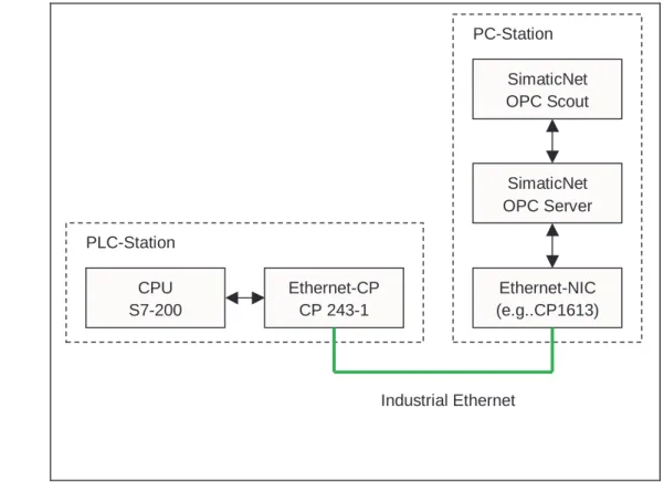
The following figure shows the components of the sample plant in principle:
Figure 1-1 Block Diagram
Environment
The controller consists of S7-200 PLC including the Ethernet communication processor (CP243-1). Via Ethernet (TP: Twisted-Pair) the controller is connected to the PC (Personal Computer). Inside the PC an Ethernet adapter (e.g. 3Com, CP1613 or others) is connected through its driver to SimaticNet OPC Server, which provides the data. The OPC Scout, an OPC Client that is shipped with SimaticNet, displays the data from the OPC Server.
Note
Using a direct connection between two Ethernet communication devices, a so-called Cross Cable is required.
PC-Station SimaticNet OPC Server SimaticNet OPC Scout Ethernet-NIC (e.g..CP1613) PLC-Station CPU S7-200 Ethernet-CP CP 243-1 Industrial Ethernet
1.2
General Description
PLC Station
When using the CP243-1 in an S7-200 environment the S7-Protocoll over Ethernet is supported. The S7-Protocoll includes different services for communication. The so-called Variable services (Put/Get) are used in this example. Here the S7-200 acts as the passive communication partner, meaning the S7-200 awaits the connection request and responds on Put-Requests (write data into the PLC) or responds on Get-Request (read data from the PLC). The S7-200 is passive and reacts on active requests, thus the functionality is called a server. Inside the S7-200 a passive S7-connection must be configured.
PC Station
The PC supports the S7-Protocoll over Ethernet. Here the protocol is executed on the network interface controller (e.g. CP1613) and the S7-OPCServer provides the data from the PLC. The OPC Client (OPC Scout) starts the OPC Server and the server runs the S7-Protocoll services (Put/Get) on the NIC. The active call of services is described as client functionality.
Communication Relations
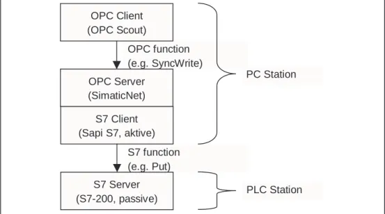
The S7 OPC Server provides, with respect to the OPC Client, a server interface compliant to the dedicated OPC Standard. With respect to the PLC the OPC Server acts as S7 Client and the PLC serves data as S7 Server.
Figure 1-2 Client – Server Relations
OPC function (e.g. SyncWrite) S7 function (e.g. Put) OPC Client (OPC Scout) OPC Server (SimaticNet) S7 Client (Sapi S7, aktive)
S7 Server (S7-200, passive)
PC Station
Connection Type
For communication between PC and controller this example uses the S7 Protocol (Put/Get services) on TCP/IP. Between the two devices a S7 Connection must be established. When communicating to OPC Server, S7-200 are always passive, thus the PC-Station actively establishes the connection. The S7 Connection is configured using NetPro (Network Projection Tool as part of NCM software package).
Note
Booth communication partners need information about the connection. The single sided specified S7 Connection must be loaded into the PC-Station. The
configuration will not be loaded into the PLC using NetPro. However, the connection (also single sided specified) must be configured and loaded into the S7-200.
1.3
Function Diagram
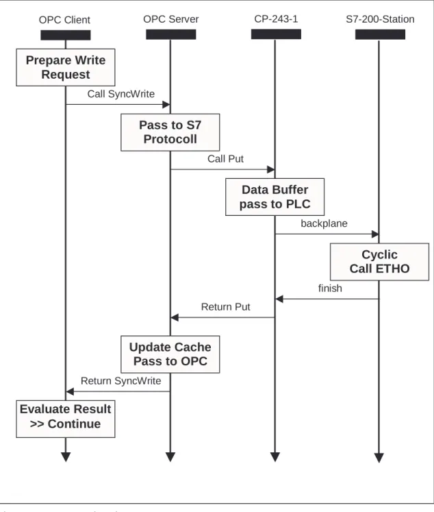
The following diagram shows the principle function of this example regarding a writing call to the PLC.
Figure 1-3 Function Diagram
OPC Client OPC Server CP-243-1
Prepare Write
Request
Pass to S7
Protocoll
Data Buffer
pass to PLC
Call SyncWriteCall Put
Return Put
Update Cache
Pass to OPC
Return SyncWriteEvaluate Result
>> Continue
S7-200-StationCyclic
Call ETHO
backplane finish1.4
Required Software
To run this example the following software packages are required.
Operating System
● Microsoft Windows 2000 Professional SP3 or Windows XP Professional SP1
SIMATIC
● SimaticNet CD 7/02, PC-Software V6.0 for Windows 2000 or SimaticNet CD 7/02, PC-Software V6.1 for Windows XP
This software package includes drivers for the communication processor CP1613 and other Ethernet cards (NIC), das S7 Protocol and the S7 OPC Server including the OPC Scout.
● SIMATIC NCM S7 IE V5.2 or SIMATIC STEP 7 V5.2
This software package includes configuration software HWKonfig and NetPro with the required Hardware Catalog.
● SIMATIC STEP 7 MicroWin V3.2 SP1
This software package includes programming- and configuration tool for S7-200 controllers.
1.5
Required Hardware
PC Station
IBM PC including Ethernet Card (e.g. Communication Processor CP1613)
PLC Station
SIMATIC S7-224 Controller including Ethernet Communication Processor CP243-1
Miscellaneous
Ethernet Hub and 2x Ethernet Cable with RJ45 connector, so-called patch cable or 1x Cross Cable for direct connection devices.
1.6
Suitability for a Different Hardware Configuration
Important
The samples relate to specific hardware configurations. These must exist to ensure problem-free operation.
If you want to use a different configuration, adaptations will be necessary. (See also the notes below)
Note
Using a different CPU (e.g.: CPU 222)
If you want to use a different CPU, you only need to run the Ethernet-Assistant as part of Step7-MicroWin again and the Module-Command-Byte must be changed. Using a different Ethernet card in the PC
If you want to use a different PCI adapter from the CP1613, you only need to replace the adapter in the hardware configuration (HWKonfig). When using third party NIC the CP „IE General“ must be selected.
In this chapter the configuration of the PC Station and the programming of the Controller is shown in form of a Step-by-Step description.
2.1
PC Station
General
After placing the Ethernet adapter (e.g. CP1613) in the PC Station, the SimaticNet PC Software V6.x must be installed. Installing the card, the SimaticNet Software including the required license is described in a different document. Refer to the notes in the product manual and related product information including the read me files.
Note
Regarding this documentation fault free placement and fault free installation of SimaticNet PC Software and NCM PC Software is assumed.
Step-by-Step
The following steps describe the configuration and set up of connections. Important dialogs are illustrated.
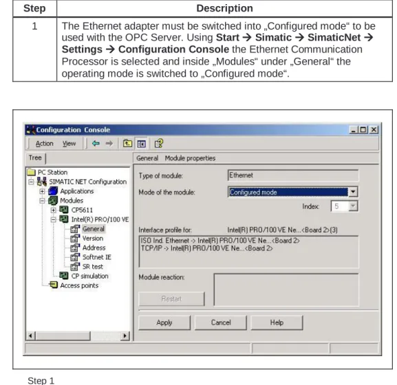
Step Description
1 The Ethernet adapter must be switched into „Configured mode“ to be used with the OPC Server. Using StartÆÆÆÆSimaticÆÆÆÆSimaticNetÆÆÆÆ SettingsÆÆÆÆConfiguration Console the Ethernet Communication
Processor is selected and inside „Modules“ under „General“ the operating mode is switched to „Configured mode“.
Step Description
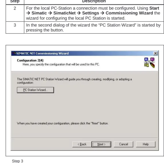
2 For the local PC-Station a connection must be configured. Using Start
Æ ÆÆ
ÆSimaticÆÆÆÆSimaticNetÆÆÆÆSettingsÆÆÆÆCommissioning Wizard the
wizard for configuring the local PC Station is started.
3 In the second dialog of the wizard the “PC Station Wizard” is started by pressing the button.
Step Description
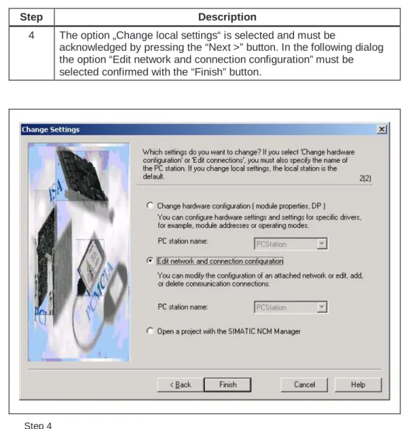
4 The option „Change local settings“ is selected and must be
acknowledged by pressing the “Next >” button. In the following dialog the option “Edit network and connection configuration” must be selected confirmed with the “Finish” button.
Step Description
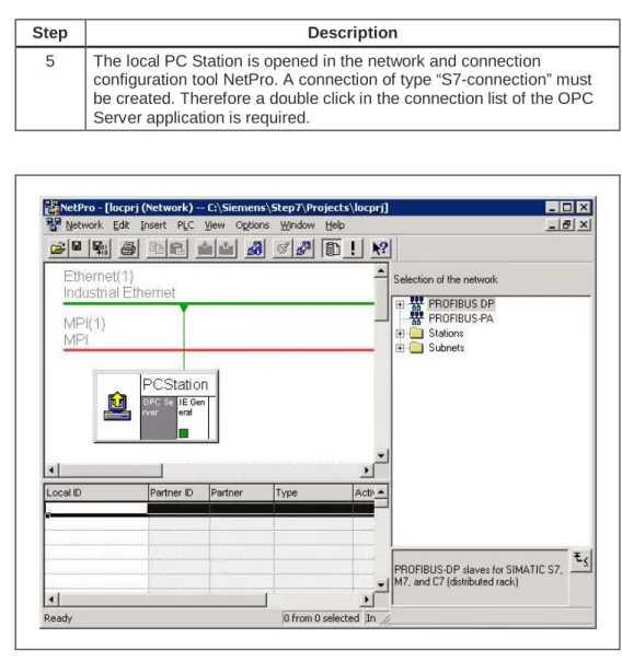
5 The local PC Station is opened in the network and connection configuration tool NetPro. A connection of type “S7-connection” must be created. Therefore a double click in the connection list of the OPC Server application is required.
Step Description
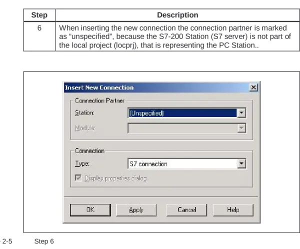
6 When inserting the new connection the connection partner is marked as “unspecified”, because the S7-200 Station (S7 server) is not part of the local project (locprj), that is representing the PC Station..
Step Description
7 The properties dialog of the S7 connection needs the IP-Address of the partner device (here CP 243-1).
Figure 2-6 Step 7
Note
Step Description
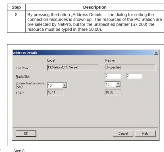
8 By pressing the button „Address Details...“ the dialog for setting the connection resources is shown up. The resources of the PC Station are pre selected by NetPro, but for the unspecified partner (S7 200) the resource must be typed in (here 10.00).
Step Description
9 After closing all properties dialogs the new configuration must be complied using “Save and Compile”. Than the S7 connection must be loaded into the PC Station using PLCÆÆÆÆDownloadÆÆÆÆSelected Stations
Figure 2-8 Step 9
Note
After downloading the PC Station a yellow exclamation mark flashes in the down right in the taskbar. This indicates a new diagnostic message in the Station Configuration Editor stating a successful restart of the OPC Server and Ethernet adapter as well as the station manager. Opening the Configuration Editor is interpreted as confirmation and the yellow exclamation mark disappears.
Note
In the case of a faulty download the diagnostic messages of the Station
Step Description
10 After confirmation of all following steps of the Commissioning Wizard using the buttons “Next >” and “Finish” the Configuration Console opens up automatically. Here the selection of protocols should be set to the actually used ones only.
Figure 2-9 Step 10
Note
Depending on the selection of protocols the address space of the OPC Server can look different.
2.2
PLC Station
General
After installing the Communication Processor CP243-1 in the PLC Station, a passive S7 connection must be configured. When communication to the OPC Server the 200 must always be configured as S7 Server, additionally the S7-200 will always be the passive communication partner.
The installation of the Communication Processor, the wiring and commissioning is described in an additional document. Refer to the stated notes and the related product information.
Note
Regarding this documentation a fault free installation, wiring and commissioning of the Communication Processor CP 243-1 is assumed.
Step by Step
The following steps describe the configuration of connections and programming of the CPU. Important dialogs are illustrated.
Step Description
1 From Step7-Microwin “Ethernet Wizard is started. This can be done using the menu bar ToolsÆÆÆÆEthernet Wizard or directly using the
Navigation Bar (left side).
2 The module position is set in the second dialog of the Wizard. The default position “0” is located directly next to the CPU, all other positions increase from there on.
3 The IP Address and the Subnet mask is set in the third dialog of the Wizard.
Figure 2-10 Step 3
Note
The IP-Addresses shown in the Figure are examples and can be different.
Note
The BOOTP Server for dynamically assigning the IP-Address should not be selected because configuration of the OPC Server’s connection (PC Station) expects a fixed IP Address.
Step Description
4 To calculate the Command Byte all output bytes (QB), that are located before the CP243-1, must be added. The next following (not taken) byte will be the Command Byte. E.g. the onboard output bytes of CPU 224 use QB0 and QB1, the next unused Command Byte will be QB2. Additionally the number of connections is set, to be configured during the following dialogs.
Step Description
5 The required properties are set for the requested connection. The S7-200 runs as server and responds to connection requests of the OPC Server (PC Station). Additionally the local properties of the connection (CP243-1) are set to the IP-Address from which connect requests will be accepted (here the IP of the PC Station must be typed in). Within the remote properties of the communication partner the TSAP is defined (here “10.11” compare NetPro S7 connection PropertiesÆÆÆÆ
Address Details)
Figure 2-12 Step 5
Note
The settings of the IP-Address and TSAP must be identically to the settings made during the connection configuration in NetPro (PC Station).
Step Description
6 After finishing the connection configuration the required memory must be reserved to avoid overwriting of configuration data.
7 The configuration data is stored within the V-memory. Memory area of correct size must be provided. The Wizard can suggest unused memory.
Figure 2-13 Step 7
Step Description
8 During the next step a subroutine (ETH0_CTRL) is generated and will be available in the engineering environment.
9 The subroutine (ETH0_CTRL) must be called once during each cycle (Main). The routine initializes the CP243-1 and provides the error codes.
2.2.1 Parameters of Subroutine (ETH0_CTRL)
Figure 2-14 Subroutine
Input parameter EN
Permanently set to “1” (SM0.0), to excetute the subroutine in every cycle.
Output parameter CP_Ready
1 = CP is ready to operate, 0 = CP not ready to operate.
Output parameter Ch_Ready
Data type Word, each individual bit of the lower byte is dedicated to a certain channel (connection). E.g.bit x.0Æconnection 0. The value of each bit indicates that the connection is established and ready for this channel or not. High byte is not used yet.
Output parameter Fehler
2.2.2 Cyclic Program (Main)
Extract of AWL Code
The following extract of code shows the principle operation of the subroutine to demonstrate the cyclic function call with the required parameter set.
Network 1 //CP initialize
LD Immer_ein
This chapter describes the download of the configuration and program of all required components and the steps for commissioning.
3.1
Overview
General
The so-called download describes the process to provide configuration information for the dedicated device. Using an engineering tool (Setp7, HWKonfig, NetPro) a configuration is created. The configuration data includes information about the IP-Address as well as connection information. In addition system blocks including e.g. TSAPs are generated. This system configuration data is transmitted to the device during the “download” of the station.
Block Diagram
The following figure shows the devices and their configuration tools as used in this example.
Figure 3-1 Download
CPU 224
CP 243-1 Ethernet
adapter OPC Server
S7-connection Step 7- MicroWin
Ethernet Wizard
Step 7 HWKonfig / NetPro
192.168.147.120 TSAP 10.00 192.168.147.100 TSAP 11.10 load load incl. information on:
3.2
PC Station
General
The PC Station consists of Ethernet adapter and OPC Server. After installing the SimaticNet PC Software the configuration tools HWKonfig (Hardware
Configuration) and NetPro (Network Configuration) are available. The Commissioning Wizard guides through the different steps and launches the configuration tool.
Local Project
For the PC Station automatically a local project (Step7 project) is generated that consists of PC Station representing the local computer. This Step7 project (locprj) includes exactly one rack of type “Simatic PC Station” and this rack resides exactly one application of type “OPC Server” (usually in slot 1). If the Ethernet adapter was set to “configured mode”, the rack hosts a communication processor of type “IE General” (usually in slot 5).
Hardware Configuration (HWKonfig)
The hardware configuration is generated and, if required, changed using the tool HWKonfig. Within the object properties of a device e.g. “IE-General” the IP-Address can be defined and the subnet mask is set. The object properties of the “OPC Server” are used to change specific protocol settings. However, the default settings of the S7 protocol must not be changed for this example. By pressing the button “Save and Compile” the system data is generated and with “Download to Module” this data is loaded into the device. The “Access Point” of the application Step7 (S7ONLINE) must be set to “PC internal (local)”. A detailed description can be found in the online help files related to SimaticNet PC Software.
Network configuration (NetPro)
The network configuration is generated using the tool NetPro. When selecting the application “OPC Server” additional connections can be added to the connection list. The properties of a connection can be changed e.g. the connection can be renamed, the local and remote P-Address can be set and the TSAPs are defined. All this properties characterize a unique connection. The “Access Point” of the application Step7 (S7ONLINE) must be set to “PC internal (local)”. A detailed description can be found in the online help files related to SimaticNet PC Software.
3.3
PLC Station
General
The PLC Station is build from CPU (224) and Communication Processor (CP 243-1). After installation of Step7MicroWin software (Version 3.2+SP1 upwards) the Ethernet Wizard is available as configuration tool. The Wizard guides through the required steps and generates the subroutine.
S7-Project
The S7-Project is generated by MicroWin. Besides the PLC program the project contains information about the used hardware (e.g. CPU type). From CPU S7-222 upwards connection the CP 243-1 is supported.
Ethernet Wizard
The Ethernet Wizard is used for configuration and settings regarding connection properties. The information is stored in a reserved memory area and the finally generated subroutine (ETH0_CTRL) accesses the configuration data. The
subroutine initializes the Communication Processor and transfers the data from the CPU to the CP and vice versa. Thus the subroutine must be called cyclic (Main); the routine is downloaded together with the other part of the program. The download can be done through the PPI-cable, or through the Ethernet CP itself (once it has an IP-Address). A detailed description can be found in the online help of the Ethernet Wizard.
General
Regarding this example process data can be set (forced) and monitored on two different ways.
In Step 7 MicroWin a chart is generated. The variables in that table are updated online through the PPI cable or through the Ethernet connection. Using the chart status single data points can be set.
The OPC Client (OPC Scout) shipped with the software package SimaticNet PC Software the OPC Server is started and connected, through Ethernet the chosen variables are monitored. Using OPC Scout data points can be written as well.
Block Diagram
In the following diagram the possibilities of accessing process data are shown (simplified illustration).
Figure 4-1 Control and monitoring
CPU 224 CP 243-1
Ethernet adapter OPC Server Step 7-MicroWin (Chart Status) SimaticNet OPC Client (OPC Scout) ONLINE alternatively
ONLINE over Ethernet
PPI cable Ethernet
COM Port
For operator control and monitoring the OPC Client sipped with SimaticNet PC Software is used. More detailed description of the OPC Client can be found in the online help of SimaticNet Software.
To access data of an OPC Server the client has to start the server (connect). The client must at least add one group and than add items in that group. If granted by the access rights the client than can access the data of the server.
Note
Any other OPC Client can be used instead of OPC Scout, however, it must be compatible to the specification OPC Data Access 2.x.
Step Description
1 The OPC Scout is launched with StartÆÆÆÆSimaticÆÆÆÆSimaticNetÆÆÆÆ Industrial EthernetÆÆÆÆSOFTNET Industrial EthernetÆÆÆÆOPC Scout
2 To connect to SimaticNet OPC Server the ProgID (OPC.SimaticNet) must be selected and double clicked.
3 At least one group must be created. Therefore the dedicated node “New Group” must be double clicked in the tree.
items are selected and taken over into the right hand item list by clicking the “arrow” button. Finishing with “OK” the tags are added to the group and can be monitored.
5 On right mouse button in the “Value” column the “Write” dialog shows up.
Figure 4-3 Step 4
Note
The window of OPC Navigators shows all variables that are known by the OPC Server. The known address space of the Server can be extended using “New Definition” node in the tree. The operator must type in the correct syntax for the variable to be successfully added.
For operator control and monitoring with Step7 MicroWin the so called “Chart Status” is used. This table is created within the project connects online (e.g. usually through PPI-cable) to the CPU.
Step Description
1 The PPI cable must be connected to the active CPU.
2 In the opened S7 project „Chart Status“ is launched with the button in the function bar.
3 The symbolic name or the direct address of the favored variable must be prompted in the “Address” column.
Note
The status bar in MicroWin shows whether the table is active or not. If online the used bus, transmission rate and status of CPU must be shown correctly.
Client Demanding services and data
COM Port Serial interface of the PC
CP Communication Processor
CPU Central Processing Unit
MicroWIN Engineering tool for S7-200 controllers
NetPro Engineering tool for Simatic Network connections
OLE Object Linking and Embedding
OPC OLE for Process Control
PC Personal Computer (IBM PC)
PLC Programmable Logic Controller
PPI Point to Point Interconnection
Server Providing services and data
SIMATIC Siemens automation systems