NK Series
Internet Protocol Server
User Guide
NK-IPS Internet Protocol Server · User Guide
• Ross Part Number: 9807DR-1004-03• Release Date: March 12, 2013. Printed in Canada.
The information contained in this Guide is subject to change without notice or obligation.
Copyright
© 2013 Ross Video Limited. All rights reserved.
This work is proprietary and confidential to Ross Video Limited, its subsidiaries and its other affiliated corporations and may not be copied, distributed, sold or otherwise used or relied upon without the express written permission of Ross Video Limited. Reproduction or reverse engineering of copyrighted software is prohibited.
Patents
This product is protected by the following US Patents: 4,205,346; 5,115,314; 5,280,346; 5,561,404; 7,034,886; 7,508,455; 7,602,446; 7,834,886; 7,914,332. This product is protected by the following Canadian Patents: 2039277; 1237518; 1127289. Other patents pending.
Notice
The material in this manual is furnished for informational use only. It is subject to change without notice and should not be construed as commitment by Ross Video Limited. Ross Video Limited assumes no responsibility or liability for errors or inaccuracies that may appear in this manual.
Trademarks
• is a registered trademark of Ross Video Limited.
• Ross, ROSS, and ROSS®, are registered trademarks of Ross Video Limited.
• Microsoft, Encarta, MSN, and Windows are either registered trademarks or trademarks of Microsoft Corporation in the United States and/or other countries.
• All other product names and any registered and unregistered trademarks mentioned in this guide are used for identification purposes only and remain the exclusive property of their respective owners.
Important Regulatory and Safety Notices
Before using this product and any associated equipment, refer to the “Important Safety Instructions” listed below so as to avoid personnel injury and to prevent product damage.
Products may require specific equipment, and /or installation procedures be carried out to satisfy certain regulatory compliance requirements. Notices have been included in this publication to call attention to these Specific
requirements.
Symbol Meanings
The exclamation point within an equilateral triangle is intended to alert the user to the presence of important operating and maintenance (servicing) instructions in the literature accompanying the product. Failure to heed this information may present a risk of damage or injury to persons or equipment.
Warning
The symbol with the word “Warning” within the equipment manual indicates a potentially hazardous situation, which if not avoided, could result in death or serious injury.Caution
The symbol with the word “Caution” within the equipment manual indicates a potentially hazardous situation, which if not avoided, may result in minor or moderate injury. It may also be used to alert against unsafe practices.Notice
The symbol with the word “Notice” within the equipment manual indicates a situation, which if not avoided, may result in major or minor equipment damage or a situation, which could place the equipment in a non-compliant operating state.Warning
Hazardous
Voltages
The lightning flash with arrowhead symbol within an equilateral triangle is intended to alert the user to the presence of uninsulated "dangerous voltage" within the product’s enclosure that may be of sufficient magnitude to constitute a risk of shock to persons.
ESD
Susceptibility
This symbol is used to alert the user that an electrical or electronic device or assembly is susceptible to damage from an ESD event.
EMC Notices
US FCC Part 15This equipment has been tested and found to comply with the limits for a class A Digital device, pursuant to part 15 of the FCC Rules. These limits are designed to provide reasonable protection against harmful interference when the equipment is operated in a Commercial environment. This equipment generates, uses, and can radiate radio frequency energy and, if not installed and used in accordance with the instruction manual, may cause harmful interference to radio communications. Operation of this equipment in a residential area is likely to cause harmful interference in which case the user will be required to correct the interference at his own expense.
CANADA
This Class “A” digital apparatus complies with Canadian ICES-003.
Cet appareil numerique de la classe “A” est conforme a la norme NMB-003 du Canada.
EUROPE
This equipment is in compliance with the essential requirements and other relevant provisions of CE Directive 93/68/EEC.
INTERNATIONAL
This equipment has been tested to CISPR 22:1997 along with amendments A1:2000 and A2:2002 and found to comply with the limits for a Class A Digital device.
Warning
Important Safety Instructions 1. Read these instructions.
2. Follow all instructions and heed all warnings.
3. Refer all servicing to qualified service personnel.
4. The equipment’s external power supply AC appliance inlets are the means to disconnect the product from the AC Mains and must remain readily operable for this purpose.
5. To avoid the risk of electrical shock and to completely disconnect the apparatus from the supply AC appliance inlets prior to servicing.
6. The safe operation of this product requires that a protective earth connection be provided. A grounding conductor in the equipment's external power supply line cord provides this protective earth. To reduce the risk of electrical shock to the operator and service personnel, this ground conductor must be connected to an earthed ground.
7. Indoor Use: WARNING: To reduce the risk of fire or electric shock, do not expose this apparatus to rain or moisture.
8. Warning: This product includes an “Ethernet Port” for connection to a local area network (LAN). This Ethernet port interface is designed for intra-building networks only.
Do not connect this port to networks that go outside of the building.
Notice
Changes or modifications to this equipment not expressly approved by Ross Video Ltd. could void the user’s authority to operate this equipment.Notice
This is a Class A product. In domestic environments, this product may cause radio interference, in which case the user may have to take adequate measures.Warranty and Repair Policy
The product is backed by a comprehensive one-year warranty on all components.
If an item becomes defective within the warranty period Ross will repair or replace the defective item, as determined solely by Ross.
Warranty repairs will be conducted at Ross, with all shipping FOB Ross dock. If repairs are conducted at the customer site, reasonable out-of-pocket charges will apply. At the discretion of Ross, and on a temporary loan basis, plug in circuit boards or other replacement parts may be supplied free of charge while defective items undergo repair. Return packing, shipping, and special handling costs are the responsibility of the customer.
This warranty is void if products are subjected to misuse, neglect, accident, improper installation or application, or unauthorized modification.
In no event shall Ross Video Limited be liable for direct, indirect, special, incidental, or consequential damages (including loss of profit). Implied warranties, including that of merchantability and fitness for a particular purpose, are expressly limited to the duration of this warranty.
This warranty is TRANSFERABLE to subsequent owners, subject to Ross’ notification of change of ownership.
Extended Warranty
For customers that require a longer warranty period, Ross offers an extended warranty plan to extend the standard warranty period by one year increments. For more information, contact your regional sales manager.
Environmental Information
The equipment that you purchased required the extraction and use of natural resources for its production. It may contain hazardous substances that could impact health and the environment.
To avoid the potential release of those substances into the environment and to diminish the need for the extraction of natural resources, Ross Video encourages you to use the appropriate take-back systems. These systems will reuse or recycle most of the materials from your end-of-life equipment in an environmentally friendly and health conscious manner.
The crossed-out wheeled bin symbol invites you to use these systems.
If you need more information on the collection, reuse, and recycling systems, please contact your local or regional waste administration.
You can also contact Ross Video for more information on the environmental performances of our products.
Notice
Changes or modifications to this equipment not expressly approved by Ross Video LimitedCompany Address
Ross Video Limited
8 John Street Iroquois, Ontario Canada, K0E 1K0
Ross Video Incorporated
P.O. Box 880
Ogdensburg, New York USA 13669-0880
Ross Video Australia
Unit 24, 49 Corporate Boulevard Bayswater VIC 3153
Australia
General Business Office:
Fax:
(+1) 613 • 652 • 4886 (+1) 613 • 652 • 4425
Technical Support: (+1) 613 • 652 • 4886
After Hours Emergency: (+1) 613 • 349 • 0006
E-mail for Technical Support: [email protected]
E-mail for General Information: [email protected]
Contents
Installation
1
NK-IPS Components ...1-1 Overview ...1-1 NK Switchboard in DashBoard ...1-1 T-Bus Control System ...1-1 The Heartbeat ...1-1 Power Supply ...1-2 Connecting the NK-IPS ...1-2 Overview ...1-2 Connecting the NK-IPS to a Network ...1-2 Connecting the NK-IPS Direct to a PC ...1-2 Connecting the NK-IPS to NK Series Devices ...1-3 Installing DashBoard ...1-3 Overview ...1-3 System Requirements ...1-3
Configuration and Operation
2
Overview...2-1 Configuring and Using the NK-IPS ...2-1 Default Configuration ...2-1 The NK-IPS Front Panel ...2-1 Reset Button ...2-1 Status LEDs ...2-1 Ethernet LEDs ...2-1 Automatic Device Discovery ...2-2 NK-IPS Connection Window ...2-2 Overview ...2-2 Opening the NK-IPS Connection Window and Querying Devices ...2-2 Manually Detecting an NK-IPS ...2-3 NK-IPS Configuration ...2-4 Overview ...2-4 NK Series IPS Tab ...2-4 Update IPS Network Settings ...2-7 NK Switchboard Configuration and Operation ...2-7 Switching ...2-8 Source, Destination, and Level Buttons ...2-8 Configure IPS ...2-9
Appendix A: NK-VCP and NK-Hub
A
NK Virtual Control Panel ...A-1 Overview ...A-1 Starting the NK-VCP ...A-1 Adding an NK-IPS ...A-1 Client Control Password ...A-3 Source, Destination, and Level Buttons ...A-3 Switching ...A-4 Protecting Outputs ...A-4 Machine Control Button ...A-4 NK-Hub...A-4 Installing NK-VCP...A-4
Overview ... A-4 System Requirements ... A-5 Installing the Java Runtime Environment (JRE) ... A-5
Appendix B: Troubleshooting
B
The NK-IPS...B-1 Network/Connection Problems ...B-1 The NK-VCP...B-1 Error Messages ...B-1 Network/Connection Problems ...B-2 General Problems ...B-2
Installation
NK-IPS Components
Overview
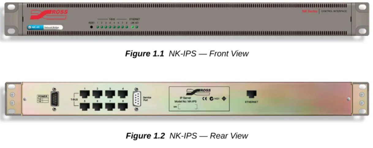
The NK-IPS (Internet Protocol Server) with the DashBoard control system software allows configuration and control of the NK-IPS and other NK routing system devices, enhancing the capability of any installed Ross products by providing access to the entire range of functions.
Figure 1.1 NK-IPS — Front View
Figure 1.2 NK-IPS — Rear View
NK Switchboard in DashBoard
The NK Switchboard, accessible through DashBoard, acts as a virtual panel for any router device. NK Switchboard enables control of multiple NK Series routers through multiple NK-IPS devices, with alternating between each NK-IPS as needed.
For More Information on...
• the NK Switchboard, please refer to “NK Switchboard Configuration and Operation” on page 2–7 or the NK Series plugin Help File in DashBoard.
T-Bus Control System
The NK-IPS is connected to other devices via the T-Bus Control System, a multi-drop RJ-45 control system supporting collision detection and half-duplex communication. The T-Bus Control System minimizes cable connections between devices, acting as both a reliable means to provide phantom power to devices and as the communications line.
Devices on the T-Bus Control System with collision detection support ensure that if two devices transmit messages at the same time they will not send incorrect data to other devices on the line. T-Bus devices that support collision detection are able to monitor communication on the line to ensure that no two devices are transmitting at the same time.
The NK-IPS does not support collision detection.The Heartbeat
The NK-IPS indicates its status using a pulsating front panel LED called the Heartbeat.
Figure 1.3 Heartbeat Display
Power Supply
The NK-IPS is powered by a +15V DC external power supply. This can be either an NK-P1 power supply which is shipped as standard or an NK-RP1/NK-RPN1 redundant power supply purchased as an option.
Connecting the NK-IPS
Overview
The NK-IPS has eight T-Bus connections (RJ-45) to connect to devices. This provides options for connection of T-Bus devices either as a daisy-chained or star configuration, or a combination of the two topologies. The single Ethernet port (RJ-45) is for a connection to a network hub or network card. The RS-232 port is for factory use only (service and maintenance) and it is not for customer use.
Figure 1.4 NK-IPS Connections
The NK-IPS does not require Internet access for operation. DashBoard software is required for operation and configuration.Connecting the NK-IPS to a Network
The NK-IPS can be connected directly to a network for configuration purposes. It is recommended that the NK-IPS be connected directly to the network so that the NK-IPS can be interfaced from almost any computer on that network (the configuration information, in “Configuration and Operation” on page 2–1, assumes that the NK-IPS has been connected directly to a network).
After a physical connection has been established, a DHCP server or DashBoard can be used to configure the network settings for the NK-IPS.
If difficulties or problems are experienced when connecting the NK-IPS to a network hub, or with assigning IP addresses, please contact your network administrator.Establishing a Physical Connection
When connecting the NK-IPS directly to the network, a straight through CAT5 cable must be used to connect the NK-IPS to the network.
To connect the NK-IPS:
1. Connect one free end of the straight through CAT5 cable to a free port of the network hub.
2. Connect the other free end of the straight through CAT5 cable to the Ethernet port on the rear or the NK-IPS.
Connecting the NK-IPS Direct to a PC
The NK-IPS can be connected to a single PC (a computer that is on a network) or standalone PC (a computer that is not on a network) for configuration purposes.
If a PC that is on a network is used to interface the NK-IPS, a spare network card is required to connect the two (the other network card is used to communicate with the network).
If a PC that is not on a network is used to interface the NK-IPS, only one network card is required to connect the two.
After a physical connection has been established, the IP address of the PC can be configured and can be used to configure the IP address for the NK-IPS.
If difficulties or problems are experienced when connecting the NK-IPS to a network hub, or with assigning IP addresses, please contact your network administrator.T-Bus Connections
Power RS-232 Port
Establishing a Physical Connection
When directly connecting the NK-IPS to either a single or a standalone PC the following points must be taken into consideration:
• Use a crossover CAT5 cable to connect the NK-IPS and the PC (this is in contrast to connecting directly to a network, where a straight through CAT5 cable is used for the connection).
• If a small standalone Ethernet hub is accessible, two standard CAT5 cables can be used. The first cable is used to connect the PC to the Ethernet hub while the second connects the Ethernet hub to the NK-IPS.
If the PC does not support Auto MDIX, a crossover cable must be used.To connect the NK-IPS to a single PC that is on a network or a standalone PC that is not on a network:
1. Connect one free end of the CAT5 crossover cable to the free network card of the PC.
2. Connect the other free end of the CAT5 crossover cable to the Ethernet port on the rear of the NK-IPS. Alternatively, if a small standalone Ethernet hub is accessible, two standard CAT5 cables can be used. The first cable connects the PC to the Ethernet hub and the second connects the Ethernet hub to the NK-IPS.
Configuring the PC IP Address
Once either a single PC or a standalone PC has been physically connected to the NK-IPS, the IP address for both the PC and the NK-IPS needs to be configured. It is recommended that users familiar with networking configure the IP addresses for both a single and a standalone PC, as well as the NK-IPS.
This topic only applies to single or standalone computers connecting to the NK-IPS; it does not apply when the NK-IPS is connected directly to the network.For More Information on...
• how to configure the NK-IPS when it is connected directly to a network, please refer to “NK-IPS Connection Window” on page 2–2.
Connecting the NK-IPS to NK Series Devices
To connect the NK-IPS to other NK Series devices (routers, panels, and control devices), connect a CAT5 cable to one of the T-Bus RJ-45 ports on the rear of the NK-IPS and connect the other end to either of the RJ-45 ports of the device. Most NK Series devices are equipped with two RJ-45 ports for looping or daisy chaining devices.
Installing DashBoard
Overview
DashBoard can be downloaded at http://www.rossvideo.com/dashboard.
DashBoard is used to configure and operate NK systems and individual NK Series devices. The NK-IPS Connection window in DashBoard is used to locate and to configure NK-IPS devices.
System Requirements
For More Information on...
• DashBoard system requirements, please refer to the DashBoard User Manual available at http://www.rossvideo.com/dashboard.
Configuration and Operation
Overview
Configuring and Using the NK-IPS
The NK-IPS is used for configuration of devices and components and can be interfaced using configuration utilities on a PC.
The NK-IPS needs to be configured for use within a network. The NK-IPS Connection window in DashBoard can be used to find the network settings of the NK-IPS once the NK-IPS has been connected to a network.
For More Information on...
• connecting the NK-IPS to a PC, please refer to “Connecting the NK-IPS Direct to a PC” on page 1–2.
Default Configuration
The factory default configuration for the NK-IPS ensures that it can be connected and used straight out of the box. There are no passwords set for configuration of devices. The T-Bus address is set to 254.
The NK-IPS Front Panel
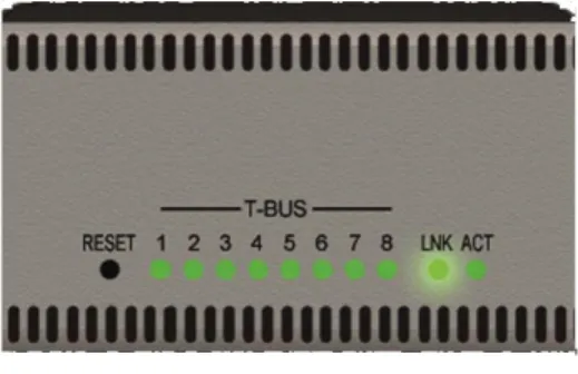
The front panel of the NK-IPS includes status LEDs for T-Bus and network activity, as well as a RESET button.
Figure 2.1 Status LEDs on Front Panel of the NK-IPS
Reset Button
The RESET button can be used in the event of device failure where the Heartbeat stops pulsing, the link LED (LNK) turns off, or the activity LED (ACT) stops flashing. In some cases, looping or daisy-chaining too many devices on one line may cause a communication failure or a power dropout (with devices that are supplied phantom power via the T-Bus line).
The reset button can be used as a last resort if errors are encountered, but no physical problem can be sourced (disconnected or severed CAT5, power cable, etc).
Status LEDs
The eight status LEDS on the left of the front panel represent the T-Bus connectors on the rear of the NK-IPS. These LEDs will light when data is transmitted to, or sent from, the NK-IPS.
Ethernet LEDs
The Ethernet LEDs behave exactly like the LEDs on a network card. When a connection is established, the link LED (LNK) will turn on. When any network activity is transmitted or received, the activity LED (ACT) will blink.
Automatic Device Discovery
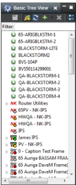
When DashBoard is opened, devices appear automatically in the Basic Tree View.
Figure 2.2 Basic Tree View in DashBoard
If automatic device discovery is not enabled or is unable to locate devices, devices can be located and added manually using the NK-IPS Connection window.
For More Information on...
• automatic device discovery and manually adding a device, please refer to the section “Configuring Devices” in the DashBoard User Manual.
• manually locating or adding a device, please refer to the section “NK-IPS Connection Window” on page 2–2.
NK-IPS Connection Window
Overview
The NK-IPS Connection window enables users to use DashBoard to locate an NK-IPS, select an NK-IPS to add from the device list, or to manually add an NK-IPS by entering the network settings.
Information such as the device name, IP address, netmask, gateway, port number, serial number, and software version are available in the NK-IPS Connection window.
Opening the NK-IPS Connection Window and Querying Devices
When devices are connected to the NK-IPS, they can be queried to check status and also to modify their network settings.
To open the NK-IPS Connection window and query devices:
1. Open DashBoard.
2. In the Basic Tree View section, click the Add New Connection menu ( ) and select NK IPS Connection
The NK-IPS Connection window opens and displays the devices on the network.
Figure 2.3 NK-IPS Connection window
Manually Detecting an NK-IPS
If an NK-IPS is not detected, it can be manually added by entering its IP address using the Manually Detect Device
window before DashBoard can be used to interface the NK-IPS, as well as other devices.
To manually detect an NK-IPS:
1. Open DashBoard.
2. In the Basic Tree View section, click the Add New Connection menu ( ) and select Manual Connection
(or select File > Manual Connection from the menu).
The Manually Detect Device window opens.
Figure 2.4 Manually Detect Device window
4. Click Finish.
The device is added to the connection list.
NK-IPS Configuration
Overview
The NK-IPS uses the NK Series IPS device tab in DashBoard to allow users to configure the NK-IPS.
NK Series IPS Tab
The NK Series IPS tab allows users to configure interface and security options for the NK-IPS, as well as having the ability to assign a name and brief details for the device itself.
Any changes to the parameters on the NK Series IPS tab will need to be sent to the NK-IPS using the Send Configuration button before they take effect.Figure 2.5 NK Series IPS tab
Device Details
Version (read-only) – the software version.
Network Settings – click this button to open the Update IPS Network Settings dialog box to configure the network settings for the NK-IPS.
Serial Num (read-only) – the serial number is set in the factory before shipping and is unique to each device. This parameter is not user configurable.
Firmware (read-only) – the firmware version used by the NK-IPS.
Details – assigned by the user to give a device specific details. For example, a physical location or a brief description of its use.
This field has a maximum of 16 characters and is used for description and identification only.
Address – this address is used within the overall control system to identify devices. Each device must be given a unique T-Bus address to avoid hardware and communication conflicts.
The valid value range for assigning an individual device T-Bus address is 1-255.
MAC Address (read-only) – the Media Access Control address (MAC address) is the unique hardware address for a device on a network. This parameter is not user configurable.
Name – this field can be assigned by the user to uniquely name a device.
This field has a maximum of 16 characters and is used for description and identification only.
Group – a group number can be assigned by the user to organize devices into groups. For example, users can assign separate group numbers for devices in different physical areas.
This field has a maximum of 10 characters, and by default is blank.
Network Settings
IP Address – the IP address of the device.
Netmask – the IP netmask of the device.
Gateway – the IP gateway of the device.
DHCP – the NK-IPS is configured to automatically obtain network settings from a Dynamic Host Configuration Protocol (DHCP) server. Since most networks have a DHCP server available, this method is applicable to most users and is the recommended method. Select this check box to use DHCP.
When DHCP is enabled, the NK-IPS will attempt to acquire network settings from a DHCP server on power up. If successful, the NK-IPS will use the acquired network settings. If it is unable to acquire the network settings after one minute, the NK-IPS will use the following network settings:• IP address: 192.168.20.100 • Netmask: 255.255.255.0 • Gateway: 0.0.0.0
SLP – select this check box to enable usage of Automatic Device Discovery in DashBoard. This is enabled by default.
The network settings, other than the SLP check box, can also be configured using the Update IPS Network Settings dialog box. Please refer to “Update IPS Network Settings” on page 2–7 for details.For More Information on...
• Automatic Device Discovery, refer to “Automatic Device Discovery” on page 2–2.
Client Settings
Use Client Control Password – when this check box is selected, the password is activated and required when applications external to the NK-IPS issue switch requests. When this check box is not selected, a password is not required, regardless of what text has been entered into the Client Control Password field.
Client Control Password – the Client Control Password option assigns a password for the use of client devices (such as Virtual Control Panels). Assigning a password will request users to log on to allow switching routers connected to the NK-IPS.
The password field is case sensitive and has a maximum value of 20 characters. The Use Client Control Password
Client TCP Port – defines which port is used for network communication. By default, the TCP Port is 5000, and any client devices/apps should be setup with the same port number.
MC-1 Interface
Throttle Switch Requests – this check box must be selected on the primary NK-IPS to serialize and retransmit switch requests on the T-Bus when using master control.
Remote IPS IP Address – on a primary NK-IPS, this field is set to 0.0.0.0. On a secondary NK-IPS, enter the IP address of the primary NK-IPS.
This is only used when using a second NK-IPS to segregate traffic from other devices such as control panels and the NK-3RD.Remote IPS Port – on a primary NK-IPS, this field can be left as the default port value of 5000. On a secondary NK-IPS, enter the TCP Client Port value of the primary NK-IPS.
This is only used when using a second NK-IPS to segregate traffic from other devices such as control panels and the NK-3RD.Connections
Max DashBoard Connections – enter a limit for the number of DashBoard connections that the NK-IPS will allow at any given time. The default value is three and the maximum allowed is five.
This is only applicable to DashBoard connections. The maximium total number of Number of connected Clients is 20.Number of connected Clients – displays how many clients are connected to the NK-IPS. The number of DashBoard connections to the NK-IPS allowed at any time is dependent on the setting in Max DashBoard Connections (maximum of five) , but up to twenty clients total. If the max clients are already connected, an NK-IPS can auto-detect but not auto-connect.
In the instance that three DashBoard clients are connected, right-click on the device in the Basic Tree View and select Force Connection. This will disconnect the oldest connection and allow a new user to access the IPS. This field is read-only.
Log off Client – select the check box of a client to forcibly disconnect the client.
Reset
Reset IPS – select this check box to reboot the NK-IPS. This function does not clear the NK-IPS settings. The
RESET button on the front panel will perform the same function.
Any changes to the parameters on the NK Series IPS tab will need to be sent to the NK-IPS using the Send Configuration button before they take effect.Other Functions
Refresh – click this button to revert to the configuration previously sent to the device.
Send Firmware – click this button to open a file browser to select a software/firmware file to send to the device.
Send Configuration – click this button to upload the settings to the device. All configuration items become active only after uploading.
Reboot – N/A – feature currently not available in DashBoard.
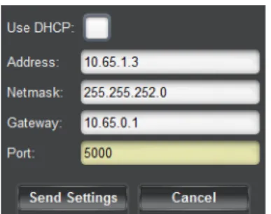
Update IPS Network Settings
The network settings can also be configured using the Network Settings section, including enabling and disabling SLP. Please refer to “Network Settings” on page 2–5 for details.Figure 2.6 Update IPS Network Settings dialog box
Use DHCP – the NK-IPS is configured to automatically obtain network settings from a Dynamic Host Configuration Protocol (DHCP) server. Since most networks have a DHCP server available, this method is applicable to most users and is the recommended method. Select this check box to use DHCP.
When DHCP is enabled, the NK-IPS will attempt to acquire network settings from a DHCP server on power up. If successful, the NK-IPS will use the acquired network settings. If it is unable to acquire the network settings after one minute, the NK-IPS will use the following network settings:• IP address: 192.168.20.100 • Netmask: 255.255.255.0 • Gateway: 0.0.0.0
Address – the IP address of the device.
Netmask – the IP netmask of the device.
Gateway – the IP gateway of the device.
Port (read-only) – the port number of the device.
Send Settings – click this button to send the settings to the device.
Cancel – click this button to close the dialog box without applying changes.
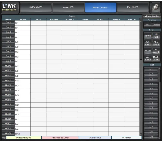
NK Switchboard Configuration and Operation
The NK Switchboard enables the routing matrix to be monitored and optionally controlled on any router on any NK-IPS detected on the network. The NK Switchboard is configured using the NK Switchboard tab in DashBoard.
It is recommended to configure the NK Switchboard globally before performing any switches.Once DashBoard has been installed, the NK Switchboard can be accessed by clicking on the NK Switchboard button ( ) from the toolbar. If the Switchboard has already been opened in the work area, activating it from either the menu or the toolbar will open it as a device tab in the device view of DashBoard.
Figure 2.7 NK Switchboard tab
Switching
The NK Switchboard is designed to emulate basic behaviour of the RCP-NK1. Switches are performed by first selecting the Level(s) required to be switched, then by selecting the Output, and finally selecting the Input.
When an Output has been selected, all Input buttons pressed thereafter will switch to that output. This is indicated by the blue line highlighting the current output selection.
Source, Destination, and Level Buttons
The Input (Source), Output (Destination), and Level buttons displayed on the NK Switchboard can be edited individually on-the-fly as required by right-clicking on the desired button and editing the fields. The button edit menu enables users to define text labels for the buttons display (Edit Text), the relative input, output or level value (Edit Value), as well as Add or Delete buttons.
The number of inputs, outputs, and levels can be configured using the Configure IPS dialog box. Click the
Configure IPS button ( ) to open the Configure IPS dialog box.
For More Information on...
• the Configure IPS dialog box, please refer to “Configure IPS” on page 2–9.
The Level Buttons
The Level buttons, when selected, enable switching on the corresponding levels. The total number of Level buttons shown is reliant on the number entered in the Configure IPS dialog box.
The Input (Source) Buttons
The Input buttons select the source or sources to be switched on the levels previously selected. The total number of
Input buttons shown is reliant on the number entered in the Configure IPS dialog box.
The Output (Destination) Buttons
The Output buttons select the destination for the source to be switched on the levels previously selected. The total number of Output buttons shown is reliant on the number entered in the Configure IPS dialog box.
Virtual Routing Button
Press the Virtual Routing button to have NK Switchboard perform all switches in virtual routing mode. If de-selected, any routing devices controlled through NK Switchboard will use physical switching.
The NK-VRC virtual routing core is required for virtual routing and resource management.The Function Keys
The NK Switchboard function keys provide Machine Control switching (the MC button) and protecting of selected inputs/outputs (the Protect button). For the Protect and MC buttons to be active, they must be enabled from the
Configure IPS dialog box.
Protects
The NK Switchboard displays protected outputs by either a yellow highlight, or a pink highlight (use the Key at the bottom of the NK Switchboard tab as a reference). Outputs that are highlighted yellow are protected by that computer and outputs that are highlighted pink are protected by another user or another panel in the system. For the protect system to be accurate, each panel and computer operating DashBoard must have its own unique address, configured in the Configure IPS dialog box.
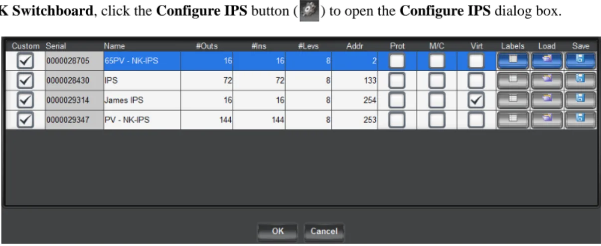
Configure IPS
Use the Configure IPS dialog box to configure the number of inputs/outputs and levels, and to turn on protects and machine control functions.
In NK Switchboard, click the Configure IPS button ( ) to open the Configure IPS dialog box.
Figure 2.8 Configure IPS dialog box
Custom – select this check box to save custom settings when saving a .nks file. Any changes to the settings of an NK-IPS in the Configure IPS dialog box will automatically select the check box.
Serial (read-only) – the serial number of the device.
Name – the name of the device.
#Outs – double-click inside the box to enter the number of outputs (destinations).
#Ins – double-click inside the box to enter the number of inputs (sources).
Addr – By default, the NK Switchboard T-Bus address is the same as the NK-IPS T-Bus address, but it can be changed. The most common reason for changing the address would be when using resource management.
Prot – select this check box to enable the protect function.
M/C – select this check box to enable the machine control function.
Virt – select this check box to enable virtual routing and resource management.
The Virt check box will be selected in the Configure IPS dialog box by default if an NK-VRC is intsalled as part of the system connected via T-Bus to the NK-IPS.Labels – click this button to import global labels. In order for the loaded .nks file to be applied to NK Switchboard, the selected NK-IPS needs to be re-selected in NK Switchboard before any changes will be effected.
Load – click this button to load a saved configuration from a .nks file.
Save – click this button to save the configuration to a .nks file.
OK – click this button to load the changes and close the Configure IPS dialog box.
Cancel – click this button to close the Configure IPS without applying changes.
For More Information on...
Appendix A: NK-VCP and NK-Hub
NK Virtual Control Panel
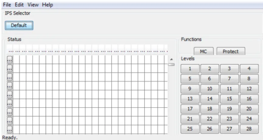
Overview
The NK Virtual Control Panel (NK-VCP) communicates via the NK-IPS and enables monitoring and control of the router matrix. If required, it is also possible to control multiple systems, alternating between each as needed. As the NK-VCP works in conjunction with the NK-IPS, NK-VCP control can be password protected to only allow authorized users to perform router functions.
The NK-VCP runs in the Java platform, using version 1.4.2 or later of the Java Runtime Environment (JRE). This allows the application to run on any system that supports the Java Virtual Machine (VM). The same program can run on Windows, Mac OS, Linux, and other platforms.
For the NK-VCP to load, the JRE must first be installed.
Figure A.1 The NK Virtual Control Panel
Note:
• Although the NK-VCP will operate with Java Runtime Environment 1.4.2 and later, it is recommended that users have the latest JRE installed on their computer before using the NK-VCP.
For More Information on...
• installing the NK-VCP, please refer to “Installing NK-VCP” on page A–4.
Starting the NK-VCP
After installation, the NK-VCP can be started from the link placed on the desktop or from the Start menu.
All communication requests and activity are shown in the bottom left corner of the NK-VCP interface.
Adding an NK-IPS
Multiple NK-IPS configuration devices can be added to the one NK-VCP. When the NK-VCP is first loaded, the default NK-IPS will need to be configured. To add or change the settings for the default NK-IPS, or add another NK-IPS to the NK-VCP, first select Preferences from the Edit menu.
The Preferences Dialog Box
The Preferences dialog box is used to add or change configuration of the NK-VCP, the NK-IPS device(s) to be interfaced, and the network details required for the NK-VCP and the NK-IPS to communicate with each other.
Figure A.2 Preferences dialog box
# (Number) – indicates the NK-IPS devices available to the NK-VCP.
IPS Name – shows a unique name for each NK-IPS added the to NK-VCP. Unique or descriptive names can be assigned to distinguish NK-IPS devices from one another.
IP Address – The IP address is required for the NK-VCP to connect to an NK-IPS and is the link for network communications. The IP address will first need to be detected via the IPS Connection window in DashBoard and entered into this field.
Num Outs – specifies how many outputs are to be viewed and controlled by the NK-VCP for a particular NK-IPS.
If the output range of routers connected to the NK-IPS exceeds the number of outputs (Num Outs) specified in the Preferences dialog box, the remaining outputs will not be shown on the NK-VCP.Num Ins – specifies how many inputs are to be viewed and controlled by the NK-VCP for a particular NK-IPS.
If the input range of routers connected to the NK-IPS exceeds the number of inputs (Num Ins) specified in thePreferences dialog box, the remaining inputs will not be shown on the NK-VCP.
Num Levels – specifies how many levels are to be viewed and controlled by the NK-VCP for a particular NK-IPS. The maximum number of levels for the NK Series routers is eight, and the default value for any NK-IPS added to the NK-VCP is also eight.
Address – defines the T-Bus address that the NK-VCP will use when sending switch requests to the NK-IPS. By default, the NK-VCP’s address is 253. If multiple NK-VCPs are to be used within the one NK system, it is strongly recommended that they be given different addresses within that system because it is necessary for proper function of protects.
TCP Port – defines which port is used for network communication. By default, the TCP Port is 5000 but must match the port defined on the NK-IPS network settings.
Early versions of the NK-IPS Firmware (v1.00 to v1.02) used the TCP Port 4444, and was not configurable. The NK-VCP must be configured to this TCP Port when being used with early NK-IPS firmware. It is recommended that users upgrade NK-IPS firmware when using the NK-VCP.Firmware revisions can be determined by opening the tab of a device in the Basic Tree View section of DashBoard and viewing the Device Details section.
For More Information on...
Client Control Password
If the Client Control Password has been activated from the Client Settings section of the device tab in
DashBoard, users will be prompted to enter that password after the NK-IPS has been selected.
Figure A.3 Enter Password prompt
When entered, passwords are masked. If an incorrect password is entered, the following error message will be displayed:
Figure A.4 Error Message warning
Source, Destination, and Level Buttons
The In (Source), Out (Destination), and Level buttons displayed on the NK-VCP can be edited as required by right-clicking on them. The button edit menu enables users to define the text the buttons display (Edit text), the respective input, output, or level value (Edit value), and Add or Delete buttons.
The Level Buttons
The Level buttons, when selected, enable switching on the required levels. The total number of Level buttons shown is reliant on the number entered in the Preferences dialog box.
Figure A.5 Level buttons
The Input (Source) Buttons
The Input buttons select the source (or sources) to be switched on the levels previously selected. The total number of Input buttons shown is reliant on the number entered in the Preferences dialog box.
The Output (Destination) Buttons
The Output buttons select the destination for the source to be switched on the levels previously selected. The total number of Output buttons shown is reliant on the number entered in the Preferences dialog box.
Figure A.7 Output buttons
Switching
The NK-VCP is designed to emulate basic behavior of the RCP-NK1.
To perform switches:
1. Select the Level(s) required to be switched.
2. Select the Output.
3. Select the Input.
When an Output has been selected, all Input buttons pressed thereafter will switch to that output. This is indicated by the blue line highlighting the current output selection.
Protecting Outputs
The Protect button is used to lock the current output (destination) from switching by other control panels or virtual control panels.
Clicking Protect will protect the current destination. Clicking Protect a second time will clear the protect.
If a switch is attempted for an output that has been protected, a message will be displayed describing the cause of the error.
Machine Control Button
The Machine Control button (MC) is used to reciprocally switch the source (master) and destination (slave) selected. Click MC to enable machine control operation and then press the required destination and source.
For More Information on...
• the Machine Control operation and reciprocal switching, refer to the NK Series User Guide.
NK-Hub
NK-Hub is a software application that allows multiple T-Bus segments to be bridged together via NK-IPS gateways. It can be used to extend the range beyond the limit of T-Bus cabling.
To use the NK-Hub, the Java Runtime Environment is required.
For More Information on...
• installing and operating the NK-Hub, please refer to the NK-Hub User Guide.
Installing NK-VCP
Overview
To use the NK-VCP, the Java Runtime Environment must first be present on your system. If this software is not present on your system, or if you are unsure, follow the guidelines below to ascertain whether it needs to be installed or updated.
System Requirements
• Intel Pentium 200Mhz or equivalent • Microsoft Windows XP or later • 32MB of RAM
• 150MB of available hard-disk space
Installing the Java Runtime Environment (JRE)
The Java Runtime Environment is required for NK-VCP operation.
Determining Previous JRE Installations
If you are unsure what version (if any) of the JRE is installed on your computer, you will need to open a command line prompt.
To determine previous JRE installations in Windows 7:
1. From the Start menu:
• select All ProgramsJAccessoriesJCommand Prompt or, • select Run and type cmd
2. Once you have opened the Command Prompt, type java -version and press Enter.
To determine previous JRE installations in Windows XP:
1. From the Start menu, select All ProgramsJAccessoriesJCommand Prompt
2. Once you have opened the Command Prompt, type java -version and press Enter.
If you have JRE installed, a message will inform you of which version and build you are running, if you have an earlier version than 1.6, then you will need to download and install the latest version.
If you receive a message that says java is not recognized as an internal or external command then you will need to download and install the latest version.
To install the NK-VCP:
1. Double-click install.exe.
2. Follow the onscreen instructions.
Appendix B: Troubleshooting
The NK-IPS
The following problems and questions are related to the NK-IPS, with brief explanations and troubleshooting help. For questions regarding other problems or to report problems, contact Ross Technical Support.
Network/Connection Problems
Most NK-IPS network problems should be solved by your Network Administrator and are usually simply TCP/IP address or port problems. Contact your Network Administrator for networking and address problems.
The NK-VCP
The following problems and questions are related to the NK-VCP, with brief explanations and troubleshooting help. For questions regarding other problems or to report problems, please contact support staff.
Error Messages
Wrong
Password
An incorrect password has been entered.
• Try entering the password a second time. If the same error message is displayed, ensure that the caps lock is not on.
• If users have forgotten their password altogether, look for it in the NK-IPS Client Control Password field or contact support staff.
NK
‐
IPS
“IPS
Name”
has
maximum
licensed
number
of
virtual
panels
connected.
Upgrade
License.
The NK-IPS has the maximum number of NK-VCPs connected to it.
• Ensure that all NK-VCPs connected are being used, if they are not, close them to clear communication to the NK-IPS.
Cannot
Switch
‐
Output
Protected
The output for the attempted switch has been protected by another NK-VCP or control panel.
• To clear the protect, locate the NK-VCP or control panel that initially activated the protect and press the Protect
button/key.
Cannot
Protect
‐
No
response
from
Level
x
The level that requires protection has briefly gone offline or is busy. • Query the devices from in DashBoard and ensure that it is online. • Check all physical connections to the router (T-Bus and power). • Check for, and amend, alarms on the router’s Device Properties page.
Cannot
Protect
‐
Output
already
Protected
by
another
The output for the attempted protect has been protected by another NK-VCP or control panel.
• To clear the protect, locate the NK-VCP or control panel that initially activated the protect and press the Protect
button/key.
Error
using
System
Look
and
Feel.
Defaulting
to
Cross
Platform
Look
and
Feel.
The JRE encountered an error when applying the operating system look and feel, the default Java look and feel is used instead.
Network/Connection Problems
The
NK
‐
VCP
does
not
successfully
connect
to
an
NK
‐
IPS
The NK-IPS and NK-VCP must have matching TCP ports to enable communication within a network. Prior to version 1.03 of the NK-IPS firmware and version 1.03 of the NK-VCP software, the TCP ports were both locked to port 4444 and were not user configurable. Due to some Windows security problems, some network configurations will block port 4444 for all TCP/IP communications.
It is recommended that both the firmware of the NK-IPS and the NK-VCP software be upgraded and an available port be used for communications.
General Problems
Not
all
Inputs
or
Outputs
are
shown
The Input and Output buttons do not show all available sources and destinations. By default, when an NK-IPS is added in the Preferences dialog box, the Number of Inputs and Number of Outputs are set to 16. For a 32x32 size router, the inputs and outputs 17 to 32 will not be displayed.
• The Number of Inputs and Number of Outputs need to be configured to match or exceed the router size in the
Preferences dialog box.
• In the case of the NK-S32, which actually has 34 inputs and 34 outputs, the Number of Inputs and Number of Outputs need to be configured to match or exceed the router size in the Preferences dialog box.