Commercial Heat Pump
Water Heaters
Technology for Efficient Electric Service
Water Heating in Commercial Buildings
A heat pump water heater (HPWH) is an effective and efficient way to provide hot water for commercial buildings. The system uses a water-heating heat pump to move heat from a cool reservoir such as air and transfer this heat into water. The system employs an evaporator, compressor, condenser, expansion valve, hot water circulating pump and controls to accomplish this function. Usually, an additional water storage tank is installed along with the HPWH so that the HPWH runtime is long and the system can meet much of the daily water heating load. Since the HPWH provides service water heating by moving heat rather than by
generating the heat, the HPWH tends to be much more efficient than an electric resistance water storage tank. In the case of the HPWH, units with a coefficient of performance (COP) higher than 3.0 can be found. This means that for every kWh of electrical energy to the HPWH, more than three kWh of thermal energy is produced as hot water.
One of the major benefits of the HPWH is the cooling that is generated as the HPWH operates to heat water. If the HPWH has an air-cooled evapora-tor that is located inside the building, then this cooling can be used to help cool the building interior during times when the HPWH is working to generate hot water. The HPWH is usually located to target spot cooling where it is needed. Generally, the economic attractiveness of the HPWH grows in cases where spot cooling can be utilized.
This Federal Technology Alert (FTA), one in a series on new technologies, describes commercial HPWH tech-nologies, the types of systems that are available, and provides informa-tion on manufacturers, system sizes, and references for further information. Moreover, this FTA takes the reader through the initial steps needed to examine potential applications for the HPWH, to size a system to meet a water demand, and to provide spot cooling according to space cooling needs within a building.
Federal
Technology
Alert
A publication series
designed to speed the
adoption of
energy-efficient and renewable
technologies in the
Federal sector
The U.S. Department of Energy requests that no alterations be made without permission in any reproduction of this document.
Technology Selection
The commercial HPWH is one of many energy-efficient technologies which have been carried through the R&D stage and brought to market. The FTA series targets technologies which appear to have a large hereto-fore untapped Federal potential. New technologies were identified through trade journals and through direct correspondence. Numerous responses were obtained from manufacturers, utilities, trade associations, research institutes, Federal sites, and other interested parties. Based on these responses, the technologies were evaluated in terms of potential energy, cost, and other benefits to the Federal sector. They were classified either as just coming to market or as having been installed in a number of loca-tions and where operating experience is available. Technologies which are new and for which little operational data are known can be considered for field demonstration through FEMP and industry partnerships, while technologies for which field data already exist are considered as topics for Federal Technology Alerts. The presence of a large number of success-ful applications puts the commercial HPWH in this latter classification.
Potential
The commercial HPWH has the greatest potential for efficiency gains in replacing electric resistance water heating. Although much commercial water heating is done using natural gas, electric water heating constitutes 0.05 quadrillion Btu of primary energy (source energy for an electric utility). This amounts to almost 5 billion kWh of electric energy used for water heating in commercial buildings. Substituting a commercial HPWH with a COP = 3 in 20% of the commercial sector where electric
resistance water heating is currently done would reduce the electric water heating energy consumption for the entire sector by 13%. Additional opportunities for the commercial HPWH lie in supplementing fossil-fired water heaters and providing cooling where economic.
Application
Based on the FEMP analysis, commercial HPWH systems are likely to be economically attractive particu-larly in applications where the cooling provided by the HPWH can be used. These applications include kitchens in fast-food and sit-down restaurants, commercial and coin-operated laun-dries, hotels and motels, and other types of buildings which use large amounts of hot water. Commercial HPWH systems range in capacity from about 10,000 Btu/h to nearly 800,000 Btu/h. This range covers the majority of water heating applications.
Field Experience
There have been a large number of installations of commercial HPWH systems both at Federal sites as well as buildings in the private sector; present estimates are that there are about 50,000 HPWH systems in operation, and most of these are in commercial buildings. Case studies prepared by utilities and others emphasize the cooling benefit of the technology as well as the water heating efficiency.
Case Study
A commercial laundry is an attrac-tive setting for the HPWH because of large hot water draws and a concur-rent need for space cooling and dehumidification. The baseline setting was a coin-operated laundry facility which used a gas water heater to meet a daily 2,020-gallon hot water
requirement and an air conditioner to satisfy the cooling needs of the build-ing for 12 hours each day. As an alterna-tive to the original water heating system and additional air conditioning system proposed for installation, a remote-package HPWH system with a split evaporator coil was chosen to meet the hot water demand and provide the necessary spot cooling inside the facility. As part of this study, an algorithm was developed and used to size the HPWH as well as the water storage tank. The installed cost of the HPWH system was $12,100 more than for the air conditioner upgrade to the existing gas water heating system. However, the present value of energy savings of the HPWH system over the baseline system was nearly $46,000. This produced a savings-to-investment ratio of 3.8 and a simple payback of four years.
Implementation Barriers
Commercial HPWHs are a mature technology, and they can be very attractive when applied appropriately in the Federal sector. Good applica-tions are buildings with heavy and long hot water demands which can take advantage of the inherent effi-ciency of the HPWH. Apparent barriers to the technology include a general lack of awareness of the technology by installers and knowl-edge of where best to apply HPWHs. The HPWH system is more complex to install than a like-for-like replace-ment water heater, and requires (initially) more study to select the best system for the job. Moreover, depending on the type of system, a HPWH installation requires expertise in air conditioning as well aspipefitting (water circulation system); this combined expertise is less readily available than for water heating or air conditioning alone.
1
Federal
Technology
Alert
Abstract
The energy required for service water heating can be a large compo-nent of a building s total energy use. Conventional electric storage water heaters are approaching the thermody-namic limit of 100% efficiency, and gas water heaters somewhat less. By transporting heat from a source (e.g., outside air or air inside a building) rather than producing it by combusting gas or using electric resistance elements, the commercial heat pump water heater (HPWH) is 2 to 3 times more efficient than a conventional water heater.
Heat pump water heaters have been designed by a number of U.S. manu-facturers to be easily installed in buildings and to be compatible with existing water heating systems. As it heats water efficiently, the HPWH provides cooling as an additional benefit. The most cost-effective applications for commercial HPWHs are those which can take advantage of this cooling benefit. In cases where the cooling opportunity is captured, paybacks can be as little as 1 year. The high water heating efficiency combined with the cooling benefits tends to favor applications where there
Commercial Heat Pump Water Heaters
are large hot water demands which occur for much of the day, and where there is a simultaneous need for spot cooling. Laundries, restaurants, and some dormitories are representative of good applications.
Estimates are that more than 50,000 commercial HPWH systems of various configurations are currently operating in the United States. The current market is 2,000-4,000 units annually; however, the potential U.S. market for HPWH designs is much larger.
This Federal Technology Alert pro-vides information on HPWH technolo-gies: where they have been installed, how they have worked, and who is producing them as well as information to help a facility manager evaluate applications where HPWHs could be installed and would be cost-effective. A simple HPWH sizing procedure based on any hot water draw profile is also provided to help find good opportu-nities for the technology. This proce-dure is illustrated through a case study of a coin-operated laundry facility. Finally, details on HPWH systems pro-duced by U.S. manufacturers, utilities who are promoting the technologies, and references for additional informa-tion are provided to help the reader.
3
Contents
Abstract ... 1
About the Technology ... 5
Application Domain ... 5
Energy-Saving Mechanism ... 6
Installation ... 6
Federal Sector Potential... 7
Technology Screening Process... 7
Estimated Savings and Market Potentials ... 8
Laboratory Perspective... 8
Application... 8
Application Screening ... 9
Where to Apply HPWHs ... 9
What to Avoid ... 10
Design Considerations ... 10
Multiple tank piping - series or parallel... 10
HPWH Controls ... 11
Other Installation Considerations... 11
Sizing the System ... 11
Obtaining Hot Water Use Profiles ... 13
Costs ... 13
Utility Incentives and Support ... 14
Technology Performance ... 15
Field Experience... 15
Maintenance ... 16
Case Study ... 16
The Technology in Perspective ... 18
Relation to Other Technologies ... 19
Manufacturers ... 20
Who is Using the Technology ... 22
For Further Information... 23
References ... 23
Appendixes ... 25
Appendix A - Federal Life-Cycle Costing Procedures and the BLCC Software... 26
Appendix B - Comparative Water Heating Analysis for a Generic HPWH Application ... 27
5
About the Technology
A heat pump water heater (HPWH) is a system for extracting heat from a source (air or water) and applying this heat to water. The air stream passes through one side of the unit and is cooled, and water is heated as it passes through the other side of the unit. As heat is removed from the air stream, the air is cooled and, depend-ing on the application, may be used to cool or dehumidify an occupied space. However, the principal function of the HPWH is efficient service water heating. The system for accomplish-ing this may be compared to a simple air conditioner which moves heat from a living space and rejects this heat to the outside of a building. In its most basic form, the HPWH is an air conditioner which heats water.
Generally, the first cost of a HPWH exceeds that of a conventional water heater; however, the HPWH is typi-cally 2—3 times as efficient. This means that the operating costs of the HPWH will be much lower than a conventional water heater making the HPWH the most economic of several options for water heating.
Commercial HPWHs are currently manufactured by a small number of U.S. companies, and at present, the market is small compared to markets for conventional commercial water heaters. Estimates indicate that there are about 50,000 HPWH installations over a variety of climates and building types across the United States. The current annual market for HPWHs is less than 5,000, and most of these are being installed in commercial build-ings. This market can grow substan-tially by providing information on the attributes of successful installations,
information on the available technolo-gies, and installation design guidelines for federal facility managers. This information is provided in the ensuing sections of this FTA.
Application Domain
Water heating constitutes a large fraction of the total energy consump-tion of residential buildings. In commercial buildings where large amounts of hot water are used, the energy tied up in water heating can be a significant component of the building s total energy consumption. Commercial buildings with heavy hot water demands include motels and hotels particularly ones with kitch-ens, restaurants (both fast-food and sit-down), commercial laundries, buildings with industrial processes requiring heavy hot water demands as well as other types of buildings such as dormitories or other high-density housing facilities. Most commercial water heating is done with storage water heaters which use gas, oil or electricity. The efficiency of most gas water heaters currently in use is about 65% and standby losses are about 6.5% of stored capacity per hour. An accepted measure of the energy performance of water heaters is the energy factor (EF) which takes into account thermal losses from the tank. The National Appliance Energy Conservation Act (NAECA) has established minimum energy factors for water heating equipment used in residential applications, and since many commercial applications use the same type of water heating equipment, water heaters in commercial applica-tions tend to fall under the NAECA minimum performance standards. The minimum EF depends on the storage
tank volume and how the tank is fired (gas, electric or oil). According to the NAECA, a 50-gallon electric water heater sold in the United States must have an EF of 0.86 or higher. The minimum EF for a gas water heater of the same size is 0.53 and for an oil heater, 0.50. Generally, the older the heater, the lower its efficiency. The ASHRAE through Standard 90.1b established a higher minimum perfor-mance level for storage water heating: a gas water heater which meets 90.1b must have a minimum efficiency of at least 78% and standby losses no higher than 2.3% per hour.
In the case of the HPWH, most of the heat delivered to the water comes from the evaporator of the unit, not through the electrical input to the machine. Consequently, the efficiency of the HPWH is much higher than for direct-fired gas or electric storage water heaters. The installed cost of commercial HPWH systems is typi-cally several times that of gas or electric water heaters; yet the low operating costs can often offset the higher installation cost, making the HPWH the economic choice for water heating. The HPWH becomes in-creasingly attractive in building applications where energy costs are high, and where there is a steady demand for hot water. This attractive-ness is less a function of building type than it is water demand and utility cost.
Unlike the conventional oil, gas or electric water heaters, the HPWH provides an important additional benefit: cooling. The HPWH system operates between two temperature reservoirs—one hot and one cold. Heat is removed from the cool reservoir and delivered to the high temperature
reservoir. The high temperature reservoir is water which becomes hot as the HPWH operates, and the cool reservoir may be air or water which becomes cooler as heat is withdrawn from it. Water heating with the HPWH can take place only where there is a source of available heat.
Energy-Saving Mechanism
The operating principles for HPWHs are the same as for any vapor compres-sion cycle such as a heat pump, air conditioner or chiller. These principles rely on the fact that a volatile fluid—a refrigerant such as HCFC-22 or HFC-134a—can absorb heat and evaporate (or release heat and condense) at a temperature which depends on the fluid pressure. That is, the condensing or evaporating temperature of the fluid can be controlled by the fluid pressure; the higher the pressure, the higher the condensing/evaporating temperature. In the vapor compression cycle for a HPWH, as shown in Figure 1, this principle is put to work as heat is absorbed by the working fluid (refrig-erant) at a low pressure in the evapora-tor. The compressor adds energy to
the refrigerant by raising its tempera-ture and pressure before it enters the condenser. At the condenser, which is simply a water-cooled heat exchanger, the refrigerant gives up much of its heat to water which is pumped through the condenser. The refrigerant then passes through an expansion device (orifice, capillary tube or valve) which quickly reduces the pressure of the refrigerant causing a small quantity of the refrigerant to flash into vapor. This flashing process cools the remain-der of the liquid refrigerant as it enters the evaporator ready once again to absorb heat from the air stream and to repeat the cycle. The overall process is one in which electrical energy is applied to the compressor to move heat absorbed by a cold evaporator surface to the condenser which operates at a higher temperature and pressure. The heat absorbed at the evaporator cools and dehumidifies the air in the building, and the heat released at the condenser is used to heat water. In a single pass through the condenser, the water temperature may rise 10¡F; consequently many passes are needed to heat a tank of water.
The efficiency of a HPWH is measured by its coefficient of perfor-mance (COP). Mathematically, the COP is the quotient of the desired effect (water heating or space cooling) and the energy input. The limiting COP of a gas or electric water heater is 1.0, where all of the energy input to the unit is converted into thermal energy to heat the water. Since the HPWH moves rather than generates heat, the COP can be much higher than unity. A small capacity HPWH which can provide 18,000 Btu/h of heating using 6,000 Btuh of electrical energy would have a COPheating= 18,000 Btuh/6,000 Btuh = 3.0, and COPcooling= 12,000 Btuh/6,000 Btuh = 2.0. These figures, typical of the performance of many HPWH systems, show the efficiency advantage pro-vided by a HPWH system.
Installation
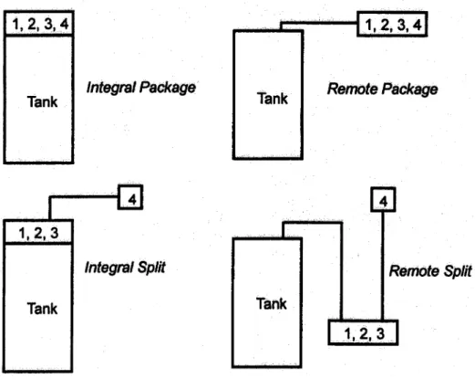
All HPWH systems have, at a minimum, the components shown in Figure 1. There are, however, a number of ways that these compo-nents can be packaged together, and this provides variety in the HPWH configurations which can be found in the market, as shown in Figure 2. At least one HPWH manufacturer produces the integral package where the HPWH is located above the storage tank and the entire system is installed as one unit. Heat is removed from the space surrounding the HPWH and used to heat water in the tank and this cools the space. The footprint required for this type of installation is about the same as would be needed for a conventional hot water tank. In the integral split configuration, the evaporator is separate from the remain-ing components. This configuration provides greater flexibility in evapora-tor location allowing it to be placed outdoors if no space cooling is needed or to be located where spot cooling is
7 needed (a ceiling location generally
works best). It is important to note that the tank is incorporated with the HPWH in both integral designs and that the cost of this system includes a tank. The remote systems, also produced by a number of manufactur-ers, are designed so that the water tank is separate from the HPWH system. This type of system can take advan-tage of an existing water storage tank for the primary water storage or can
be easily tied into most any new water storage tank. In the remote configura-tions, the system installer must lay out and connect water piping to the storage tank, and purge this piping to remove air from the lines in order for the system to work as designed. Experience has shown that problems with HPWH installations can often be traced to poor water circulation
between the storage tank and HPWH. These problems can be eliminated by following manufacturers recommen-dations and guidelines in laying out the piping for the recirculation loop. If a conventional electric or gas water heater tank is used, control modifica-tions will be needed to allow the tank to be heated by a water circulation loop from the remote condenser. A split evaporator providing greater installation flexibility is also an option for the remote system. As with any vapor compression cycle containing an evaporator, a small pipe to drain condensate from the evaporator needs to be installed and carried either outside the building or to a suitable drain.
Each of these configurations has advantages depending on the proposed installation, and the installer needs to
weigh conditions present at the site to determine the best for a particular application. All of the manufacturers provide detailed installation instruc-tions at a level which meets the needs of a skilled installer. Installers who can reference their experience with HPWH applications should be given due consideration. Installation and maintenance courses are being spon-sored by some utilities as a means for qualifying installers of HPWH systems.
Federal Sector
Potential
The potential cost-effective savings achievable by this technology were estimated as a part of the technology assessment process of the New Technology Demonstration Program.
Technology Screening Process
New technologies were identified through trade journals and through direct correspondence. Numerous responses were obtained from manu-facturers, utilities, trade associations, research institutes, federal sites, and other interested parties. Based on these responses, the technologies were evaluated in terms of potential federal-sector energy savings and procure-ment, installation, and maintenance costs. They were also categorized as either just coming to market ( un-proven technologies) or as technolo-gies for which field data and experi-ence exist.
The energy savings and market potentials of each candidate technology were evaluated using a modified version of the Facility Energy Decision Screening (FEDS) software tool(a)(Dirks and Wrench 1993).
Fig. 2. HPWH Configurations Found in the Market
(a) Developed for the Federal Energy Management Program (FEMP), the U.S. Army Construction Engineering Research Laboratories (CERL), and the Naval Facilities Engineering Service Center (NFESC) by the Pacific Northwest National Laboratory (PNNL)
Estimated Savings and Market
Potentials
The commercial HPWH was evalu-ated as an energy-efficient replacement for electric resistance water heating, which was taken to be the baseline system. From manufacturers data, a relationship between the installed cost of a HPWH system and its capacity was developed and used to estimate the cost of a HPWH system. A mid-range capacity HPWH system was chosen to deliver 1200 gallons/day of hot water. The efficiency of the HPWH system was assumed to be 2.5 times as efficient as the baseline electric resis-tance system. This corresponds to a HPWH energy factor of 2.3 if the energy factor of the baseline resis-tance storage water heater is 0.9. An energy cost analysis was conducted using the Building Life-Cycle Costing program (BLCC) subject to a real energy price of $0.076/kWh, a real discount rate of 4.1% and a 15-year expected lifetime for the HPWH. A break-even electric energy cost of $0.048/kWh was determined for the HPWH system. This represents what the cost of electricity would need to be for the baseline system to break even with the total life-cycle cost of the HPWH system operating with a real energy price of $0.076/kWh. If a value were placed on the cooling benefit delivered by the HPWH, the break-even cost would be lower, i.e., a more favorable economic outlook.
Therefore, in federal building applica-tions where electricity is currently used for water heating and the water heating demand is as assumed, the economics of the HPWH system look promising. Applications in federal and non-federal facilities which use more hot water would experience greater savings through a switchover to the HPWH system. However, each potential application for a HPWH retrofit should be evaluated individually.
Laboratory Perspective
Commercial HPWH systems have been demonstrated to be an efficient method for producing hot water. The efficiency of the system is higher with lower inlet water temperatures to the HPWH; consequently, using the HPWH to preheat water, and gas or resistance heat to carry the water up to its final temperature is an effective approach. In many applications, the HPWH can provide most of the energy needed for hot water leaving the demand from heavy water draws to be met by gas or electricity. Good applications for the HPWH are ones which require large amounts of hot water for much of the day so that the HPWH has long runtimes. Cooling delivered by the HPWH is another attribute, and applications in which hot water demands coincide with the need for space cooling are very attractive. Electrical demand reduc-tion is another inherent advantage of the HPWH, and where demand charges are part of the electric utility rate tariff, additional savings could accrue to the user.
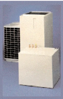
Commercial HPWH systems have been on the market for more than 10 years, and the base technology is mature. They are available in capaci-ties ranging from 10,000 Btu/h to almost 800,000 Btu/h. Manufacturers are continuing to introduce new systems including integrated, triple-function HWPH designs with outdoor heat exchangers. One such system designed for residential and small commercial buildings is shown in Figure 3. The compressor section is located indoors along with the fan coil unit and water storage tank; an outdoor heat exchanger which doubles as a condenser and evaporator is also part of the system. This gives the HPWH additional operating modes which combine space heating/cooling with water heating.
A large number of HPWH systems have been installed successfully in military bases and in commercial buildings, and, judging from a number of case studies which have been compiled principally by utilities, the experience has been positive. The keys to success are to choose applica-tions for which the HPWH is well-suited, and to ensure that the HPWH is installed and maintained properly. Based on the fact that many of the components are similar, the lifetime of the commercial HPWH should be comparable with that for air condition-ers and heat pumps used in commer-cial buildings.
Application
This section addresses many of the technical aspects of applying HPWHs in commercial buildings. The range of applications and climates in which HPWHs are best applied are addressed, and the advantages, benefits and limitations in each application are
9 enumerated. Further, the reader is
carried through a simple analysis of a water heating application including spot cooling to help provide an understanding of what leads to a good, successful application of a commer-cial HPWH system. Design and integration considerations for HPWH systems are discussed, including equipment and installation costs, maintenance considerations and relevant codes and standards. A broad look at utility programs which provide assistance to help market commercial HPWHs is provided as well.
Application Screening
Successfully applying HPWHs requires that the attributes of the technology be clearly understood, and applications are chosen such that they maximize use of the performance features and benefits of the HPWH. First, recognize that the HPWH becomes more efficient with lower inlet temperatures to its condenser. This means that the HPWH is put to best advantage in those cases where the coolest water in the storage tank is returned to the HPWH condenser for the longest time. Consequently, applications where the HPWH is used for preheating water or for swimming pool heating would make best use of the efficiency advantage that the HPWH offers. For service water heating, designs that ensure that (1) as hot water draws are made, the cold makeup water into the tank passes through the condenser of the HPWH and (2) temperature stratification in the tank, which returns the coolest water to the HPWH condenser, is most efficient.Second, the efficiency benefit of the HPWH is put to best use in applica-tions where the HPWH run times are long. This can be done by either selecting applications with long,
steady water draws or by operating the HPWH in conjunction with a large volume hot water storage tank which allows the HPWH to operate for a number of hours each day. Long
charging times also mean that a smaller capacity, more economical HPWH design can be used. In the limit, a large tank would allow a small capacity HPWH to operate continuously.
Third, the best applications are ones for which there is need for all of the cooling provided by the HWPH. In cases where there is value attributed to the cooling, the water heating benefits of HPWHs are augmented by the space cooling benefits, and this improves the economics of the application.
Fourth, the design of HPWHs requires that the cooling effect at the evaporator is always coincident with the hot water generated by the ma-chine. This means that the controls for generation of hot water need to be responsive to the thermostat setting in the water tank and to the time when space cooling could be used. More-over, since the cooling from the HPWH evaporator can be targeted, it makes sense to identify applications which would benefit by having spot cooling nearby. On-site refrigeration systems, for example, located near the cool air discharge from a HPWH could show a performance improvement.
Fifth, the low temperatures at the HPWH evaporator could be used to accomplish dehumidification as a principal function rather than space cooling. Operating the evaporator at reduced temperatures and using a low speed fan coil unit would provide useful dehumidification of the sur-rounding space.
Sixth, there are also applications for HPWH where the space cooling
benefit is not valued, and in these cases, the evaporator of the HPWH can use outside air, ventilation air from the building, or in cases where a ground water loop is available, heat from the ground. In these cases, the success of the application is strongly dependent on the ambient weather and/or site conditions.
Where to Apply HPWHs
Generally, the most favorable commercial HPWH applications are those where efficient electric water heating is needed along with a small amount of cooling. Buildings with the following characteristics tend to be attractive targets for HPWH: • localized, overheated spaces in abuilding where spot cooling is needed,
• buildings where the need for cooling coincides with the need for hot water,
• buildings where additional spot cooling is needed but where it would be difficult or impossible to run ducting or refrigerant lines to provide this cooling,
• buildings which have a significant hot water demand,
• buildings where the electrical service entrance is at capacity; yet additional hot water and cooling are needed, and
• buildings where there is interest in reducing utility costs for service hot water.
Based on these general characteris-tics, there are several commercial building types which are typically good candidates for HPWH. They include
• Laundries (coin-operated and commercial), where there is a large daily hot water requirement and where space cooling would be useful;
• Restaurants, particularly in the kitchen where large hot water demands for dishwashing coincides with a need for cooling the kitchen and its occupants; locate the HPWH evaporator to take advan-tage of the heat from the dish-washer;
• Hotels and motels - large users of hot water; locate the evaporator of the HPWH near ice machines to improve their performance; • Health clubs - for spa heating and
service water heating;
• Schools - particularly in the kitchen where hot water is used for food preparation and cleanup;
• Multifamily housing and apart-ments where hot water is provided by a single system for all residents; • Finally, in these and other buildings
where the cost of energy for conventional water heating is high and where a more efficient water heating option would be attractive.
What to Avoid
Experience with many installations of HPWHs has shown them to be very efficient and to have low operating costs. However, care must be taken to ensure that the performance advantage of the HPWH is realized. Here are some guidelines on what to avoid: • Recognize that the HPWH does not
need to provide all of the water heating needs; it may work best as a preheater for a gas or electric water heating system so that it has long run times.
• Field experience has shown that the most successful installations are the simplest; avoid applications which are overly complex to install and control.
• Avoid applying the HPWH without increasing the size of the storage tank or the number of storage tanks.
Additional storage increases run times of the HPWH and gives it the flexibility of providing spot cooling when needed.
• Avoid long duct runs if possible. Locate the evaporator of the HPWH near the source of the waste heat.
• Avoid installation of HPWH water piping with excessive lengths, small diameter and an excessive number of fittings; these cause high pressure drops and can cause the water pump in the HPWH to work against a large pressure difference between the discharge and suction. The longer the piping runs in the system, the larger the diameter of the pipe needs to be. Since the water pump in the HPWH operates as a closed piping system, only the pressure drop in the piping due to friction losses contributes to pressure head loss. The relative elevation of the storage tank with respect to the HPWH is generally not a consideration. As is custom-ary in circulating water systems, a vent at the highest point in the piping is helpful to purge air from the system.
• Avoid HPWH systems with no or minimal warranties; the expected lifetime of a HPWH which has been correctly installed and main-tained should be about the same as for other building equipment which use a compressor and longer than for the storage tank.
• Make certain that the HPWH installation is such that the coolest water available is used as the inlet to the HPWH. In the case where an electric resistance water tank is used, the lower element is normally disconnected and the coolest water temperature is at the bottom the HPWH tank. With fossil-fired tanks, this is not the case. Installa-tion guidelines provided by the
HPWH manufacturer address these issues and must be followed to realize the performance of the unit.
Design Considerations
There are areas where the econom-ics and practicality of a HPWH system can be improved by careful design. For example, in large installa-tions, it is best to use several smaller tanks piped together rather than one, large single tank. Sections of the ASME Boiler and Pressure Vessel Code govern the construction of pressure vessels with operating pressures greater than 15 psig and volumes more than 120 gallons. Since service water pressures in most U.S. locations is at least 50 psig, hot water storage tanks with volumes larger than 120 gallons could be considered as pressure vessels which fall under the ASME code requirement. This requirement makes the larger storage tanks twice as expensive as a non-coded tank. If more than 120 gallons of storage capacity is needed, use several smaller tanks. These tanks will be considerably less expensive than a single, coded tank with equiva-lent volume. In addition, several single tanks gives the customer greater flexibility in choosing locations for storage in the building.
Multiple tank piping - series or
parallel
Multiple tanks can be installed in series so that the water from the HPWH flows through both tanks, or in parallel. Each configuration has its advantages, and there have been many systems of each type installed. Tanks in series do a better job at temperature stratification between the inlet and outlet of the tank battery. With a single tank, about 70% of the tank volume is generally considered
usable. After about 70% of the tank is discharged, the delivery temperature
11 has fallen by 25¡F due to mixing in
the tank, and although hot water remains in the tank, it may not be sufficiently hot to be useful. As a result of this, guidelines for electric or gas water heaters suggest that storage tanks be oversized by 43% (100%/ 70%) to provide the needed capacity. If two storage tanks are piped in series with the cold water entering the bottom of one of the tanks, tempera-ture stratification is significantly improved and the usable water volume increases to more than 80% of the total tank volume. The improved stratification can:
• Maintain cooler water temperatures to the condenser of the HPWH during hot water recovery periods. These are periods when the hot water demand is low, and the HPWH is recirculating water from the bottom of the storage tank and returning it to the storage tank. • Reduce the storage tank size
required, and this will reduce heat losses.
• Reduce the size of the storage tank, and this will reduce the overall system cost.
In the case of parallel tanks, the water flow rate through each tank is 50% of the flow that tank would have if operated in series. This means that a system of two parallel tanks could manage a higher overall system flow than could the same two tanks in series. Low flow rates help to prevent the cold and warm water in each tank from mixing so that stratification is improved. It is important with parallel tanks that the pressure drops associated with the interconnected piping between the tanks be equal for each tank so that the flow remains balanced. This will ensure equal flow through each tank so that the full tank capacity is utilized. To accomplish
this, the interconnected piping should be large in diameter, short, and provided with as few fittings as possible. Ball valves or plumbing manifolds may also be helpful to balance the flows to each tank.
HPWH manufacturers do not agree on whether series or parallel configu-ration is best for multiple tanks. Some manufacturers feel that the small water temperature rise through the condenser places the series configura-tion at an advantage. Others consider the reduced water flow through each individual tank in a parallel configura-tion to be the key to maintaining a thermocline. Creating and maintain-ing a sharp thermocline in the system of tanks is the goal, and with proper design, either configuration will work. Stratification which maintains a sharp thermocline in the tanks keeps the coolest water entering the condenser for the longest time this lowers the condensing temperature and raises the overall system COP. The challenge is to use the small water temperature rise through the condenser to stratify tanks containing water initially at 50¡F bring them to a final temperature of around 130¡F.
HPWH Controls
Most commercial HPWHs have two controls. An aquastat is used to monitor the water temperature in the tank, and to turn off the HPWH when the temperature reaches its setpoint. The aquastat is simply a thermostat which responds to water temperature, and like a thermostat, the user controls the setpoint.
The second controller is a timeclock to limit operation of the HPWH to certain hours. These hours might define an interval in the morning or afternoon when water heating and/or spot cooling are needed. For example, the timeclock with supervisory control over the aquastat could turn off the
HPWH at the end of the day even though the aquastat is not satisfied and the water tanks are not fully charged. The next morning begins with the hot water storage depleted from the prior day so that the HPWH could turn on to charge the storage tank, and to provide spot cooling to meet customer needs early in the day. Without the timeclock, the HPWH would deliver spot cooling at the end of the day when it is not particularly useful.
Other Installation
Considerations
The cooling coil of the HPWH will require a consensate line to catch moisture condensed from the air moving across the coil and route this condensate to a floor drain or other drain. If it is possible and permitted by code to terminate the condensate line in a sanitary sewer line, a trap with cleanout will need to be installed.
A second installation requirement is supply and/or return ducting from the cooling coil. If the fan coil/evaporator unit can be located near or in the space to be cooled, no additional supply ducting is needed, and the air diffuser on the evaporator can effec-tively direct cool air where is it needed. Uninsulated return ducting with filter would be all that is neces-sary to carry air from the heat source (e.g. a dishwasher, cooktop, or over-heated rooms) to the HPWH fan coil unit. Attention to manufacturer s data on the fan performance and following good practice duct sizing procedures are all that is required for HPWH ducting.
Sizing the System
One of the keys to an efficient and cost-effective installation is proper sizing of the HPWH and the storage tank. Oversizing the HPWH leads to reduced run times, a high initial outlay for the system and reduced system
cost-effectiveness. Oversizing the storage tank also increases the initial cost of the system, restricts the possible locations for the tank in the building, and increases heat losses from the tank to the surrounding space potentially placing an extra burden on the existing building cooling system. If the HPWH is undersized, a greater fraction of the hot water demand must be satisfied by a backup (electric resistance or gas) system rather than the efficient HPWH, and the availabil-ity of spot cooling and/or dehumidifi-cation is reduced. If the storage tank is too small, there is less of an oppor-tunity to capture the cooling effect of the HPWH unless the need for cooling is coincident with the hot water demand.
Proper sizing of a HPWH system depends on the amount and accuracy of information available for a pro-posed application The more informa-tion that is known about a particular application, the better the size of the storage tank, HPWH and ancillary equipment can be determined, and the more confident one can be that the HPWH system will meet the customer s needs economically.
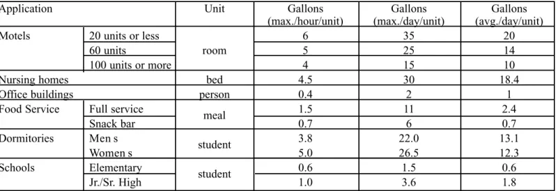
The first step in sizing a HPWH system is to determine the hourly hot water demand on the design day. Although average daily hot water use determines water heating energy consumption, the hourly demand will determine the size of the individual system components based on recovery and storage capacities. There are a number of methods which could be used to get this information ranging from measuring the hot water draw of the building to estimating methods based on the type of building and its size. To help with this task, empirical estimates of hot water demand profiles have been developed (ASHRAE) and used to size simple storage water heaters. These estimates are useful in sizing a HPWH system for a particular application. Table 1 shows typical hot water consumption data for several building types. These data can be used to determine the average and peak hot water demand for a single, dedicated facility or for a building which combines several functions.
For example, a full meal restaurant which serves 500 meals/day would typically use 1200 gallons (2.4 gal/ average meals/day x 500 meals/day) of hot water each day. This demand
can be met by a combination of recovery capacity and storage size. The smaller the storage tank, the larger must be the recovery capacity.
Applications can be combined by superposing individual components from Table 1. An enlisted men s barracks with food service, for in-stance, may be approximated as 20.3 gallons/soldier by combining the average daily hot water use in a men s dormitory with a full service cafeteria serving three meals per day {i.e., [13.1 + 3 (2.4)] = 20.3}. For a 200 person barracks, the total daily hot water demand would be about 4,000 gallons.
A rough HPWH sizing guideline is often helpful to give a feel of the capacity of a HPWH and the amount of hot water generated:
A 4- to 5-ton HPWH operating continuously will deliver about 2,000 gal./day of hot water.
Based on this rough guideline, an estimate of the HPWH capacity needed to meet the barrack s hot water demand would be in the neighborhood of 10 tons (heating). This, however, does not address the size needed for the storage tank, the fact that backup
Table 1. Typical Hot Water Usage
Application Unit Gallons Gallons Gallons
(max./hour/unit) (max./day/unit) (avg./day/unit)
Motels 20 units or less
room
6 35 20
60 units 5 25 14
100 units or more 4 15 10
Nursing homes bed 4.5 30 18.4
Office buildings person 0.4 2 1
Food Service Full service
meal 1.5 11 2.4
Snack bar 0.7 6 0.7
Dormitories Men s
student 3.8 22.0 13.1
Women s 5.0 26.5 12.3
Schools Elementary
student 0.6 1.5 0.6
13 heating (gas or electric) is available
for use, and component sizing to take advantage of spot cooling produced by the HPWH system. This estimate must be refined for design of a system, and this requires knowing the hot water hourly profile and those hours when cooling is needed.
Obtaining Hot Water Use Profiles
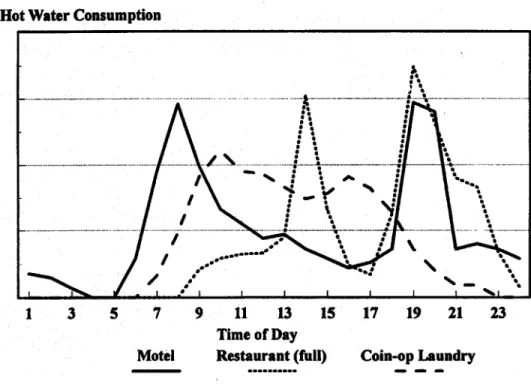
The most accurate determination of hot water use is done by measuring the hourly hot water demand for the application at hand. This is usually practical in a retrofit application where HPWH/storage is being added to an existing gas or electric water heating system. If the existing system is fully able to meet the water demand of the facility, then simply monitoring the volume of water (gallons) entering the storage tank each hour of the day will suffice. However, if there is not enough hot water capacity in the existing system, additional data on water delivery temperatures may be necessary to estimate what a constant inlet temperature profile should be. Judgement should be used to select monitoring days which are representa-tive of a typical day, and several days of hourly data should be averaged to increase confidence that the profile obtained is representative.If it is not practical to measure and track the hot water hourly consump-tion, information is available on hot water profiles for several typical applications, and from which hourly profiles can be estimated. Sample profiles are shown in Figure 4.
As might be expected, the motel profile shows significant hot water use for tubs and showers in the mornings and evenings with little use during the day. Dishwashing after lunch and dinner causes two peaks for full-service restaurants. The profile for coin-operated laundries shows that hot water is used throughout the day
although there are two peaks, one in the morning and the other in the afternoon. The water consumption (vertical axis) for each of these applications is not labeled since it depends on the size of the facility. However, these curves can be used to generate the hourly hot water con-sumption using a simple procedure: Use a scale to measure the height of the curve for each hour, then normal-ize these heights. Normalization is done by dividing the height of the curve at each hour by the total of all 24 heights. This is equivalent to normalizing the area under the profile curve, and this area is proportional to the total daily hot water consumption for the particular facility. Through this normalization procedure, the hot water profile for a facility can be estimated simply by knowing the total daily hot water consumption. As Table 1 indicates, there are sources of information on daily hot water consumption based on the number of units (beds, meals, etc.) in the facility.
The procedure is illustrated for the motel, restaurant and coin-operated laundry facility in Table 2.
Table 2 shows, for example, that the highest water draw in a coin-operated laundry occurs between 9:00 and 10:00 a.m. and during that time, the water draw is 11.1% of the total daily water use. With this technique and knowledge of the total daily water consumption of the facility, one can determine the water consumption for each hour of the day. Larger facilities would require more water; however, the generic profile shown in Table 2 would remain relatively unchanged.
Costs
The main components of a commer-cial HPWH system are of the storage tank and the HPWH. Figure 5 pro-vides information on the installed cost of a water storage tank as a function of tank size. This information was prepared from standard cost estimat-ing guides for specific tank sizes and smoothed to show a relation between tank size and cost. Figure 6 was
Table 2. Normalized Hot Water Consumption Profiles
Hour Restaurant Coin
ending Motel (full service) Laundry
1 .018 0 0
2 .015 0 0
3 .007 0 0
4 0 0 0
5 0 0 0
6 .029 0 0
7 .095 0 .016
8 .146 0 .048
9 .099 .021 .091
10 .066 .029 .111
11 .055 .032 .095
12 .044 .033 .093
13 .047 .045 .083
14 .036 .152 .074
15 .029 .066 .078
16 .022 .024 .091
17 .026 .017 .082
18 .036 .062 .064
19 .147 .174 .036
20 .140 .132 .020
21 .036 .090 .009
22 .040 .083 .009
23 .036 .034 0
24 .029 .008 0
Total 1.000 1.000 1.000
Fig. 5. Storage Tank Installed Cost
Fig. 6. HPWH Installed Cost
prepared based on manufacturer list price information of HPWH designs. This information is useful in sizing a system and provides a guideline as to how the installed cost depends on the capacity of the HPWH. As expected, the actual installed cost for a particu-lar installation depends on site condi-tions as well as vendor quotacondi-tions for equipment.
Since the cost of the HPWH itself dominates the total system installed cost, cost-effective applications tend to use small capacity HPWHs which operate for long periods of time to provide sufficient hot water for meeting a large portion of the daily integrated hot water demand for an application. The relation between storage tank size and HPWH capacity, however, depends on a number of factors including available space for
the storage tank, peak hourly hot water draw, total daily hot water draw and the need for spot cooling. In some cases, the need for additional spot cooling at certain times of the day is the driving consideration in sizing a HPWH system. This will be illustrated in the case study presented.
Utility Incentives and Support
Some electric utilities offer a range of incentives to support adoption of many water heating systems including storage water heating for load control, heat-recovery systems, solar-assisted, and HPWH systems. This helps to bring the installed cost of the system15 down and make the option more
attractive. A survey of 2321 programs conducted by 666 electric utilities found that 18 utilities offered cus-tomer rebates ranging from $1200 to $1500 for commercial HPWH sys-tems. With some utilities, the rebate amount is tied both to the power draw of the unit (kW), and to the storage tank volume. Although many utilities do not offer rebates, they provide information to consumers and perform field studies of systems installed in their service territories.
Among the most active utilities supporting the technology and incen-tives as of this writing:
Georgia Power Company - Rebate is $500/ton with installation to have a 12-h minimum daily run time; provides installer training programs. Contact: Charlie Wall at 404-368-5727.
Alabama Power Company -Rebate is $200/kW ($300/kW for Healthcare) plus $2.50/gallon for water storage tank up to 720 gallons and $2.00/gallon for 720+ gallons; provides training programs. Contact: Judy Ray at 205-250-4460
New England Electric System -Full incremental cost reimburse-ment; mechanical/electrical
system design services. Contact: Michael McAteer at 508-366-9011. Potomac Electric Power Company - Rebates of $1000/unit for HWHP (min. COP = 2) with over 50 gallons of storage. Contact: Lloyd Williams at 202-872-2467 Hawaii Electric Company - Promoting HPWH; Hawaii provides a state tax credit of 20% of system cost subject to a maximum depending on the application. Contact: Jay Mulki at 808-543-4770
Other utilities with commercial HPWH programs include:
Fort Payne Improvement Author-ity (Alabama). Contact: Steve Sax at 205-845-0671
Arizona Public Service Company. Contact: Judy Ray at 602-250-2359 Florida Power Corp. Contact: Jerry Knepprath at 813-866-4806 Rochester Gas & Electric Corpo-ration, New York. Contact: Glen Davis at 716-724-8152
Four County Electric Power Association, Mississippi. Contact: Ronnie Vernon at 601-327-8900 Ohio Edison Company. Contact: James Watson at 216-384-5828 Pennsylvania Electric Company. Contact: Anthony Garaventa at 814-533-8072
South Carolina Electric & Gas. Contact: Gene Martin at 803-733-4227
Chattanooga Electric Power Board, Tennessee. Contact: Lynda Weathers at 615-757-1327 Central Power & Light Company,
Texas. Contact: Rob Darsey at 512-881-5746
Central Vermont Public Service. Contact: Dave Yordy at 802-747-5494
Snohomish County PUD, Wash-ington. Contact: Allen Aldrich at 206-347-101
Madison Gas & Electric,
Wisconsin. Contact: Chuck Sasso at 608-252-5651
TU Electric, Dallas. Contact: C.C. Benson at 214-954-5647 Wisconsin Electric Power
Com-pany. Contact: Joann Henry at 414-221-2399.
There may be other utilities not listed here that provide rebates, low interest loans, or technical support to encourage installation of commercial HPWH systems. The commercial
marketing section of your local electric utility should be contacted to determine utility support and assis-tance which are available.
Technology
Performance
Field Experience
A number of reports and papers have been written on specific com-mercial HPWH systems, and there exist several summary publications which detail the individual installa-tions. In addition, several informal surveys of commercial HPWH systems have been conducted. One of these identified 81 case studies of HPWH installations representing a range of climates. Several utilities are very active in promoting the use of commercial HPWH systems, and produce brochures describing the installation and performance of individual HPWH systems in their service territories.
In a recent study, researchers found that HPWH installations in fast-food restaurants offer the quickest payback. This study was performed by Georgia Power Company and the Electric Power Research Institute who moni-tored 45 commercial HPWH installa-tions for at least 60 days and up to one year. Fast-food restaurants showed paybacks ranging from 9 months to 1-1/2 years as compared with gas water heaters. Simple paybacks as long as 4-5 years were found where HPWHs had been installed in full-service restaurants. In the coin-operated laundries studied, paybacks were 3-4 years. Laundries, like these other applications, appear ideal for HPWHs: when the facilities are in use, hot water is drawn and useful space cooling is provided.
Maintenance
Maintenance requirements for air-source HPWH systems are similar to those for air conditioners. The evaporator air filters require periodic replacement or cleaning; this is especially important in those applica-tions where the evaporator is located to cool a kitchen or other room where there is a concentration of airborne contaminants. Where heavy concen-trations of dust or grease are present, the evaporator coil should be cleaned on a regular basis. The cleaning frequency would depend on the application and should correspond to the cleaning requirements of conven-tional cooling coils.
On the condenser (water heating) side of the system, concentrations of calcium carbonate and other minerals in the water being heated ( hard water) can produce scale inside the condenser tubes, and this reduces the heat transfer to the circulating water. Maintenance to remove scale may be required in locations where hard water is present and a water softener is not used upstream of the HPWH evaporator.
Blowers require little maintenance only an occasional drop of oil to the motor oiling ports.
In a unitary HPWH system, the refrigeration system is sealed at the factory. In a split system HPWH design, the individual components are connected in the field with refrigerant piping. Pre-charged refrigerant lines are frequently used to eliminate the
need for system evacuation and refrigerant charging. As with other vapor compression air conditioners, any refrigerant leakage is too much, and repairs by qualified and certified refrigeration mechanics should be made as soon as possible.
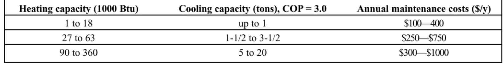
Estimates of typical maintenance costs of air-source HPWHs exhibit a considerable range. The EPRI indi-cates maintenance costs are in line with the values shown below in Table 3.
Other maintenance estimates compare the HPWH with a single zone air conditioner. Based on this assumption, the HPWH approximates a constant volume packaged rooftop cooling system, and the maintenance cost for this system is estimated to range from $33/ton to $41/ton.
In locations where the water con-tains little dissolved salts and scale build-up is minimal, and the evapora-tor works in an environment similar to that for a fan coil unit, regular annual maintenance would primarily consist of a filter changeout and unit checkover. In this case, annual maintenance estimates of $50/year for small-capacity HPWHs have been found to be the case.
Case Study
Commercial coin-operated laundry facilities represent one of the most favorable sites for applying HPWHs. They use large quantities of hot water for washing, and heat and humidity from the washers and dryers produce
high wet and dry bulb temperatures in the facility. Moreover, since the washes occur when the facility is occupied, hot water draws and the need for space cooling in the laundromat coincide. The case study is a laundromat which has a gas water heater and a building air conditioning system which is undersized and consequently unable to keep the customers comfortable. On a typical day, 100 loads of laundry are done and each load requires 20 gallons of hot water. In addition to this hot water requirement, we estimated that another 20 gallons of hot water are consumed daily by a laundry tub used for handwashing and rinsing. There-fore, the total daily hot water draw is 2020 gallons and is constant through-out the year. Prior to installation of a HPWH, a gas water heater with an efficiency of 55% was used for all water heating. The options considered were (1) to continue using the existing water heating system and to add an air conditioning system to help cool the building for 12 hours each day for 3/4 of the year, or (2) to install a HPWH to provide water heating and to use the evaporator to provide space cooling. With option (1), the new air condition-ing system would be turned off when not needed (1/4 of year), whereas with option (2), cool air from the HPWH would be ducted outside of the condi-tioned space by using a manually-operated damper for this same period of time.
Evaluation of these options required that a HPWH system be sized and
Heating capacity (1000 Btu) Cooling capacity (tons), COP = 3.0 Annual maintenance costs ($/y)
1 to 18 up to 1 $100—400
27 to 63 1-1/2 to 3-1/2 $250—$750
90 to 360 5 to 20 $300—$1000
17 designed. The design goal was to size
and install a HPWH system which would provide 2020 gallons of hot water each day and would provide spot cooling for a 12-hour period beginning at 9:00 a.m. The procedure followed to size a HPWH system to meet these conditions was based on a spreadsheet analysis shown in Table 4.
The Hourly HW draw (column B) is the fraction of the daily HW demand in the corresponding hour. This is the product of the total daily hot water demand (2020 gallons) and the fraction of that demand which occurs in that hour. These fractions are shown in Table 2 for three applications including a coin-operated laundry. Column C of Table 4 is a running total of column B.
Column D is the water heating capacity which must be present for the hours when cooling is required, and column E is the running total of column D. The design criterion specified that cooling should be delivered by the HPWH for 12 hours and that 2020 gallons of hot water were to be produced by the HPWH during that time. Consequently, about 169 gallons of hot water need to be produced by the HPWH for each hour of operation as shown. Column F is the total hot water stored or withdrawn from the tank during each hour of operation and can be determined by (col. D - col. B). Since there should be just as much hot water stored as used during the day, the total of all
entries in column F should be zero. The entry in column G is simply the amount of hot water at the beginning of the day, and column H is the sum of the initial hot water in the tank at the beginning of the day (column G) and column F.
The initial amount of hot water in the tank was chosen so that it was as small as possible while keeping some hot water in the tank at all times. A hot water runout would be indicated by a negative entry in column H. If, in the case study shown, the tank started with more than 55 gallons of hot water, the tank size would be larger than necessary, and if the amount of hot water were less than 55 gallons at the beginning of the day,
Table 4. HPWH/Tank-Sizing Spreadsheet
A B C D E F G H
Hourly HW Total HW HPWH Total HW HW Stored Initial HW HW in
Ending hr. draw draw capacity by HPWH during hour in tank tank
(gal/hr) (gal.) (gal/hr) (gal.) (gal.) (gal.) (gal.)
1 0 0 0 0 0 55 55
2 0 0 0 0 0 55
3 0 0 0 0 0 55
4 0 0 0 0 0 55
5 0 0 0 0 0 55
6 0 0 0 0 0 55
7 32 32 0 0 -32 23
8 97 129 169 169 72 127
9 184 313 169 338 -15 40
10 224 537 169 507 -55 0
11 192 729 169 676 -23 32
12 188 917 169 845 -19 36
13 168 1085 169 1014 1 56
14 149 1234 169 1183 20 75
15 158 1392 169 1352 11 66
16 184 1576 169 1521 -15 40
17 166 1742 169 1690 3 58
18 129 1871 169 1859 40 95
19 73 1944 161 2020 87 142
20 40 1984 0 2020 -40 15
21 18 2002 0 2020 -18 37
22 18 2020 0 2020 -18 37
23 0 2020 0 2020 0 55
24 0 2020 0 2020 0 55
there would be a hot water runout. Through this simple spreadsheet, the minimum tank size was determined to be 127 gallons (see 8:00 a.m.). Two 80-gallon electrically-heated water tanks were used to meet the storage required and to allow for the lack of perfect temperature stratification and full utilization of the thermal energy inside the tank. Based on Figure 5, the installed cost for both tanks was $1120.
The HPWH chosen for this case study was a packaged unit with a rated water heating capacity of 120,000 Btu/h. This was determined as the required capacity by assuming that the HPWH would raise the temperature of 169 gallons of water through an 80¡F temperature range each hour. Manu-facturers specifications for this unit indicate a heating COP = 3.2 and a cooling COP = 2.5. Based on this information, the electrical power requirements were determined to be
W = 120,000 Btu/h/3.2 = 37,500 Btu/h = 11 kW.
and the cooling delivered to space while the system is heating water is,
Qc = 2.5(37,500 Btu/h) = 93,750 Btu/h = 8 tons (nom.).
Since water heating is needed 12 hours each day for the full year, the total annual electrical energy con-sumption for the HPWH would be,
(11 kW)(12 h/day)(365 day/y) = 48,100 kWh.
The remote-package HPWH system with split evaporator coil was chosen so that it could be suspended from the ceiling and piping run to the storage tanks on the floor as shown in Figure 7. Installation of ducting and diffusers from the HPWH was straightforward, and by locating the HPWH near the ceiling, room air circulation was improved. A conden-sate line with a trap near the HPWH was also installed and run through the wall of the building.
The total installed cost of the HPWH unit was $16,500, as shown in
Figure 6, giving a total system (tanks and HPWH) installed cost of $17,600. Based on the estimate of $33/ton cooling, annual maintenance costs were taken to be $260/year.
An alternative to the HPWH de-scribed above would have been to install a 10 SEER air conditioner with the same capacity as the cooling delivered by the HPWH and to retain the existing gas water heater. Based on a rating of 10 SEER and a cooling capacity of 93,750 Btu/h, the electri-cal power consumption of the unit would have been 9.38 kW, and since the unit would be operated 12 hours each day for 3/4 of the year, the total annual electrical energy consumption would be 30,800 kWh. The total installation cost for this air condi-tioner was estimated to be $5500. Annual maintenance cost was esti-mated to be equal to that for the HPWH since both are unitary systems, both require filter replacement, and both have the same cooling capacity.
The life-cycle cost for the HPWH system and the alternative system was compared using the 1996 Building
Life-Cycle Cost (BLCC) Program, and the results are shown in the printout given in Figure 8. In this analysis, fuel costs were assumed to be $0.076/kWh (electricity) and $5.38/MBtu (natural gas). With a savings-to-investment ratio of 3.78, the HPWH system is the better economic choice even though the initial costs are higher.
The Technology in
Perspective
Many commercial HPWH systems have been installed and are operating to provide savings to the customer. Not all buildings and equipment are good candidates for a HPWH retrofit, and the designer needs to carefully
19 consider a range of options before making a decision. Where the HPWH replaces electric resistance water heating, there is usually strong justifi-cation for installation of a HPWH based on water heating energy savings alone. In cases where the cooling produced by the HPWH is useful, there is additional justification for switching to a HPWH. In cases where gas water heating is presently avail-able and being used, the HPWH may not be the best choice. The best choice depends on a number of factors including the efficiency of the HPWH, the efficiency of the gas water heater in place or potentially installed, relative fuel costs and other factors. If, in the case study presented above, the current gas water heater s efficiency were much higher or the water heating COP of the HPWH evaluated were lower, the economic analysis could have weighed in favor of a conventional water heater. Consequently, care must be taken in making general statements regarding HPWHs as compared with other water heating options. Each potential installation needs to be studied to determine what works best and is the most cost-effective approach to water heating.
The commercial HPWH has been available for many years, and many successful installations attest to the fact that the HPWH is reliable, economic and should be evaluated particularly when water heating and space cooling/dehumidification loads are large and coincident.
Relation to Other Technologies
Pool HeatersAlthough the principal focus of this FTA is efficient service water heating through the use of HPWHs, they are also useful and efficient for pool and spa heating. The water heating principle is identical to that previously described for a HPWH
which uses air as the heat source. In the case of pool heaters, the cooled air can be exhausted outdoors, or can be used to cool and dehumidify the air above the pool. Dehumidification is a particularly attractive feature for indoor pool or spa applications. Systems which provide pool water heating and operate over a number of ventilation air modes are available from a number of vendors in sizes ranging to more than 500,000 Btu/h of water heating.
Heat Recovery ChillersC h i l l e r s used to cool commercial and industrial buildings employ heat recovery techniques for water heating. Heat recovery is accomplished by using a condenser with two circuits for heat rejection: one operates with cooling tower water and the other is used for heat recovery. In the heat recovery mode, the chiller uses 10 to 20% more energy than in the heat rejection mode because the cooling tower provides lower condensing temperatures. However, in cases where chillers are needed for cooling large buildings and there is a coincident need for hot water, heat recovery chillers can efficiently provide hot water at temperatures up to 120¡F. Good building candidates for heat recovery chillers include offices, food service facilities, educational facilities and urban centers with food services, hotels and retail stores.
Desuperheaters A desuperheater is typically a coaxial refrigerant-to-water heat exchanger located between the compressor and condenser of a chiller or heat pump system. The desuperheater transfers heat from the hot (superheated) refrigerant vapor passing through the annular region of the desuperheater to water which is pumped through the center, and this water is used to meet some of the service water heating needs of a building. Since superheat represents
10 - 20% of the total heat rejected by the condenser, the capacity of a desuperheater is much less than the water heating capacity of a HPWH for a given compressor size.
Desuperheaters should be considered in air conditioning or refrigeration systems with significant on times, and where there is a need for hot water. In meeting a service water demand cost-effectively, the facility manager should evaluate use of desuperheaters on existing equipment in conjunction with HPWH
applications.
Manufacturers
Commercial heat pump water heaters, both air and water source, are being produced by several U.S. manufacturers. The average water heating capacity of the air source units provided in manufacturer data is usually measured and quoted with the evaporator air temperature at 75¡F dry bulb and 63¡F as a tank of water is heated over an 80¡F temperature range; however, some manufacturers apply other test conditions for rating the HPWH heating capacities. In the case of water-source HPWH designs, some manufacturers rate their prod-ucts with a 70¡F water inlet tempera-ture to the evaporator and a 60¡F water exit temperature from the evaporator, while others rate their units using other evaporator tempera-ture conditions. In all cases, it is important that the design/installer be aware of the rating conditions which the manufacturer used to determine water heating capacity. Multifunction, full condensing systems which provide service water heating as well as space heating and cooling are also being produced in sizes which are applicable to small commercial buildings. With some systems, a building s entire space heating and
cooling load can be satisfied in addition to much of the water heating demand.
The firms listed below were identi-fied as manufacturers of this technol-ogy at the time of publication. This listing does not purport to be com-plete, to indicate the right to practice this technology, or to reflect future market conditions.
Addison Products Company
7050 Overland RoadOrlando, Florida 32810 407-292-4400 (Phone) 407-290-1329 (Fax) Contact: David A. Ritchie Addison manufactures air-source HPWH systems with water heating capacities ranging from 23,600 Btu/h to 154,000 Btu/h and which operate using HCFC-22. In addition, Addison produces water-source designs up to about 73,000 Btu/h heating capacity.
Colmac Coil Manufacturing, Inc.
370 North Lincoln Street Colville, Washington 99114 509-684-2595 (Phone) 509-684-8331 (Fax) Contact: Joel Lewinsohn Colmac Coil produces air-source HPWH designs in capacities ranging from 13,000 Btu/h to nearly 750,000 Btu/h. The evaporator fan coil is included in the smaller sizes and the units use an HFC refrigerant.
Crispaire Corporation
E-Tech Division 3285 Saturn Court, NW Norcross, Georgia 30092 770-734-9696 (Phone) 770-453-9323 (Fax) Contact: Titu R. Doctor
Crispaire manufactures the smallest capacity (7,000 Btu/h) residential PWH