SQUID Application Note 1052-202
Coupling Magnetic Signals to a SQUID Amplifier
Matching the effective inductances of the Pickup Coil and the Input Coil to detect and couple magnetic flux maximizes the sensitivity of the detection system. In many cases, the
inductance of the SQUID is fixed, but using Pickup Coils in SQUIDs helps match inductances. You can use a flux transformer to connect the Pickup Coils directly to the SQUID, modify the Pickup Coil Inductance, or match the coils and SQUIDs. Although all of these techniques optimize the overall sensitivity of the system, modifying the number of turns on the Pickup Coil is the preferred method of matching inductance.
This application note discusses: • SQUID detection
• Designing and inductance-matching Pickup Coils
• Using flux transformers and adjusting Input Coil Inductance to optimize sensitivity
SQUID Detection
SQUIDs are very sensitive magnetic flux detectors. They detect directly-applied flux and are typically tightly coupled to an inductor. This inductor is the Input Coil that couples external flux into the SQUID. A Pickup Coil couples currents into the Input Coil. The coupled
currents generate flux that couples into the SQUID loop and are detected by the SQUID. This section describes SQUID parameters that affect the sensitivity and performance of this
circuit.
The intrinsic noise of the SQUID limits its fundamental sensitivity. This noise is usually expressed as flux noise, current noise, or energy sensitivity. Flux noise (Φn) is typically
expressed in Φo/√Hz, where Φo is a unit of one flux quanta (2 x 10 –15 Wb). This represents
the flux noise in the SQUID that would produce the same noise output from the device. This can be converted to a current noise (in) in the Input Coil of the SQUID by using the mutual
inductance (Mi) between the SQUID and the Input Coil. This is specified on the Quantum
Design data sheets as Input Coil Coupling (Wi) and is expressed in an inverse mutual
inductance unit, µA/Φo.1 The flux noise by this coupling multiplies. The equivalent current
noise in the Input Coil is generated:
n i n
i = W Φ .
(1) Another specification often quoted is the Coupled Energy Sensitivity. Calculating the noise energy in the coil needed to generate the current noise in. generates energy sensitivity. This is
calculated from the relation between energy and current in a coil. Li is the Input Coil
inductance:
n = i n2
1 2L i .
ε
(2) Manufacturers of SQUID devices supply the SQUID parameters above. In the following analysis, SQUID parameters such as the Input Coil Inductance, the Mutual Inductance, and Flux Noise are used with the Pickup Coil Inductance to optimize the sensitivity of the SQUID detection circuit.
The following equations are written for the sensitivity of the SQUID Pickup Coil circuit. They determine the optimum parameters for the system, which should yield the most sensitive circuit for the application.
1 Converting between the Input Coil Coupling and the Mutual Inductance between the SQUID and the Input
Coil is accomplished with the equation:
i
(H) -9 i
o
M = 2 x10 W (µA)
φ .
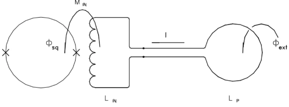
Figure 2. A SQUID detection circuit.
Direct Coupling Equations
A SQUID detection circuit is shown in Figure 2. The external flux (Φext) couples into the
single turn Pickup Coil with inductance Lp. This induces a current (I) in the circuit, which
couples a flux (Φsq) through the Input Coil of inductance. The mutual inductance of the Input
Coil and the SQUID shows as Mi. Equation 3 relates the external flux coupled into the circuit
to the flux in the SQUID using the property of conservation of flux in a superconducting circuit:
(
)
ext p i sq i
= L + L
M .
Φ Φ
(3) Note: For this analysis, you can ignore currents in the SQUID itself. These are typically at very high frequencies and have little effect on this analysis. Also, by substituting Φsq,η (the
SQUID Flux Noise) for Φsq, this equation yields the external flux sensitivity (Φext,η) of the
circuit. This is the minimum flux coupled into the Input Coil to which the system is sensitive and is the parameter that you’ll want to optimize. Expressing the mutual inductance as k√LiLsq, gives:
(
)
ext,
p i i sq
sq,
= L + L
k L L .
η η
Φ Φ
(4) Field sensitivity is often a better parameter to use instead of flux sensitivity. Here it is
expressed in terms of the external applied magnetic field where Bext,η is the external field
sensitivity, and A is the area of the Pickup loop. Note that we are assuming a uniform external field for convenience:
(
)
ext,
p i i sq
sq,
B = 1 A
L + L
k L L .
η Φ η
To determine the best way to design the circuit to optimize the sensitivity of the system, minimize the equations above. The parameters of interest are the Pickup Coil Inductance and the Input Coil Inductance. For example, to optimize the sensitivity with respect to the Input Coil Inductance Li, you need to have Li = Lp. You need to match the inductances of the Input
and Pickup Coils. This way the sensitivity becomes:
ext, p sq
sq,
= 2 k
L
L .
η η
Φ Φ
(6)
Pickup Coil Design
This section describes how to use these relationships and equations to optimize sensitivity and to design the Pickup Coil and the rest of the circuit. Although modifying the Input Coil Inductance may seem impractical, flux transformers can accomplish this (see the next section).
Designing the proper Pickup Coil for an application is often critical. Different applications will require very different configurations. The following examples of equations show that the Pickup Coils should be as large as possible and as small as possible.
Equation 5 shows that smaller Pickup Coil Inductances would be best since this would minimize Bext, η. However, notice that the area and the inductance of the Pickup Coil are
related. Typically, the area of a single turn loop is proportional to the square of the
inductance. So, you can substitute C(Lp)2 for A (where C is a constant of proportionality):
(
)
ext, p 2 p i i sq sq,B = 1 C L
L + L
k L L .
η Φ η
(7) You can see that the larger the inductance of the Pickup Coil is, the more sensitive the system appears. This is true only for a uniform field where the coupled flux increases
proportionately to the square of the inductance (in proportion to the area of the coil). On the other hand, examining other field configurations, such as the point dipole source, gives another result. The flux from a point dipole coupling into a circular coil is given where
µo is the permeability of free space, m is the dipole strength, and r is the radius of the coil:
m = o
2 m
r
Φ µ
(8) Substituting this into Equation 4 and solving for m, and you find the minimum detectable dipole strength is:
(
)
η η
µ
m = 2 r L + L
k L L .
o
p i i sq
sq,
(9) Since the inductance Lp, is proportional to r, it appears that in this case smaller Pickup Coils
would be optimal. The best way to couple to the field to be measured determines the configuration of the Pickup Coils. Once the Pickup Coil is configured, the Pickup Coil SQUID circuit can be optimized. One method of optimization is to vary the number of turns on the Pickup Coil.
Up to this point, we have only been discussing single-turn Pickup Loops. All of the equations have been written for single-turn Pickup Coils. To examine how the circuit may be optimized with multiple-turn loops, we first put equation 4 into a convenient form by defining lp, the
single turn inductance as:
p 2 p
L = n l .
(10) This equation relates the inductance of a single-turn coil to that made of n-turns of the same size. With this definition, and recognizing that the flux coupled into an n-turn coil is n times that of a single-turn coil of the same size, rewrite Equation 4 as:
(
)
ext, ext, 2 p i i sq sq,= B A = 1 n
n l + L
k L L .
η η η
Φ Φ
(11) If this equation is optimized with respect to n, the number of turns in the coil, the optimum number of turns is:
n = L l .
i p
(12) This equation relates the relative inductances of the Pickup and Input Coils for maximum sensitivity. Since n2lp is the total inductance of the Pickup Coil, Lp, this relation essentially
states that the Pickup Coil Inductance should be equal to the Input Coil Inductance. If the Pickup Coil’s inductance is significantly smaller than the Input Coil, wind it with multiple turns to improve sensitivity. If the Pickup Coil Inductance is significantly larger than the Input Coil, use fractional-turn coils in some applications. If this equation is satisfied, it looks like:
ext, ext, p sq
sq,
= B A = 2 k
l
L .
η η η
Φ Φ
(13) The sensitivity isn’t dependent on the total inductance of the Pickup Coil. It’s dependent only on the single-turn inductance of the Pickup Coil. Compare this equation to Equation 6. The same maximum sensitivity is achieved if the number of turns on the Pickup Coil is adjusted to match inductances or if the Input Coil is modified to match its inductance to that of the single-turn Pickup Coil. It isn’t necessary to change the Input Inductance of the SQUID for
every application; multiple turns is an effective way of inductance matching a small Pickup Coil to the SQUID Input Inductance.
Design the Pickup Coil first as a single-turn coil that is optimally coupled to the field of interest. After designing the coil and comparing its inductance to that of the Input Coil of the SQUID, consider adjusting the number of turns to inductance-match and achieve optimum sensitivity. The following section demonstrates another form of inductance matching using flux transformers.
Using Flux Transformers to Match Inductance
The equations for the sensitivity of a SQUID system coupled to a Pickup Coil are shown in Equations 4 and 5. Varying Lp optimizes coupling, and the inductance-matched condition
provides optimum sensitivity. Equation 4 shows that varying Li also optimizes coupling
when inductances are matched. Compare Equations 6 and 13. For the same single-turn Pickup Coil Inductance, it does not matter whether the matching is accomplished by adjusting the number of turns on the Pickup Coil or by adjusting the Input Coil Inductance. The Input Coil is part of the SQUID and cannot be adjusted. However, you can use a flux transformer circuit to adjust the equivalent Input Inductance of the SQUID (seeFigure 3). The previous section discusses how to design the Pickup Coil for maximum sensitivity by matching to the Input Coil Inductance. This section discusses how to adjust the input inductance to maximize sensitivity by matching to the Pickup Coil Inductance.
Figure 3. Using a flux transformer circuit
Using conservation of flux relations with the two superconducting circuits in Figure 3, you find:
(
)
(
)
ext
p 1 2 i f2 f
sq
= L + L L + L - M
M M .
Φ Φ
(14) Substituting kf √(L1L2) for Mf and optimizing with respect to L1 and L2, you’ll find for
optimum flux coupling:
1 p
f 2 2
i f 2
L = L
1- k , L = L 1- k .
If the effective inductance of the primary side (L1) of the transformer is calculated when the
secondary side (L2) is connected to the SQUID input, it is equal to the Pickup Coil
Inductance when the above relationship is used. The flux transformer effectively transforms the Input Coil Inductance of the SQUID to the inductance of the Pickup Coil. The secondary side of the transformer transforms the inductance of the Pickup Coil to that of the SQUID Input Coil. This is not without cost, however, for the sensitivity of the system is now:
ext. f 2 f
p sq
sq,
= 1- k + 2 k k
L
L .
η η
Φ Φ
(16) If kf = 1, indicating perfect coupling between primary and secondary, the sensitivity is
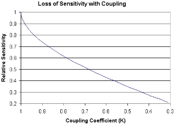
equivalent to the directly coupled, inductance-matched circuit. However, perfect coupling is typically not possible, so there is some loss in sensitivity. Figure 4 shows the loss of
sensitivity versus coupling compared to the directly coupled case. Taking an aggressive coupling of 0.9, for example, creates a loss of nearly 30% in sensitivity.
The flux transformer is an effective way of adjusting the input inductance of the SQUID so that it may be operated with optimum sensitivity. Tight coupling in the flux transformer is essential, however, since the sensitivity is strongly dependent upon coupling.
Comparing Inductance Matching Methods
Two methods of response optimization by inductance matching have been described:
• adjusting the number of turns on the Pickup Coil to match its inductance to that of the SQUID Input Coil.
• modifying the effective inductance of the Input Coil by use of a flux transformer.
Both methods offer flexibility in choosing the method of optimization of the SQUID system response for a given application.
Take a general approach and determine the size and configuration of a single-turn pickup coil that optimizes the coupling between the coil and the field of interest. If the inductance of this coil is sufficiently different from that of the Input Coil (the sensitivity is reduced to an unacceptable level), choose multiple-turn or fractional-turn coils to match the inductance following Equation 12. Otherwise, use a flux transformer. Both methods give the same theoretical sensitivity in the limit of infinite coupling (kf) in the flux transformer case. Due to
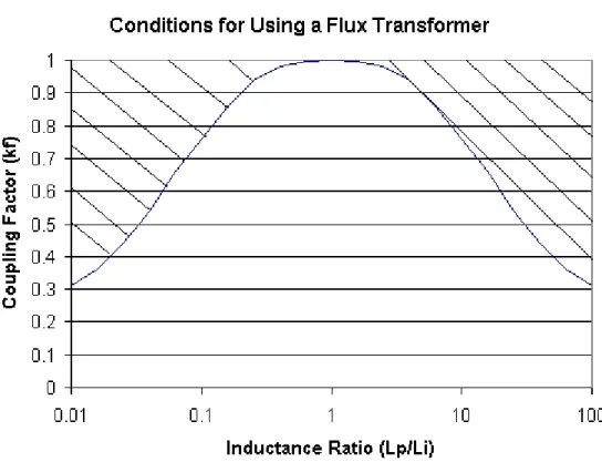
limitations on coupling, adjusting the number of turns on the Pickup Coil is preferable. If adjusting the turns on the Pickup Coil is not possible, it still may be better to avoid using a flux transformer due to the loss of sensitivity created by an imperfectly coupled transformer. The sensitivity of the flux transformer circuit is strongly dependent upon the coupling between the primary and secondary (see Figure 4). Using Equations 4 and 16, you can determine if an optimized transformer of coupling (k) benefits sensitivity for a certain inductance mismatch. Figure 5shows the result. The crosshatched region represents the range of coupling and inductance mismatch for which a transformer will provide less sensitivity than merely coupling the Pickup Coil to the SQUID directly. Outside of this region, a transformer provides better performance. Even with a coupling factor of 0.9, the inductance mismatch needs to be greater than 5:1 to benefit from a transformer.
Figure 5. Conditions for using a transformer with flux coupling
Avoid flux transformers if possible in sensitive applications since they need to be carefully designed and built to maximize coupling. They are additional cryogenic components, which need to be included in the system, and potentially cause significantly more problems than merely increasing or reconfiguring the turns of a Pickup Loop. Applications in which flux transformers are required are discussed in the next section.
Other Uses of Flux Transformers
In addition to inductance matching, flux transformers provide Faraday shield between the Pickup Coil and the SQUID. SQUIDs are very sensitive to high-frequency noise that may couple to the Pickup Loop circuit. Much of this noise couples into the circuit-common mode, either capacitively or through radiative pickup. Incorporating a Faraday shield between the primary and secondary of the flux transformer shortens this noise to the system ground and keeps it from interfering with the SQUID operation. This is primarily an electrical effect. The Faraday shield may also affect the coupling of high-frequency magnetic signals through the transformer. The shield, usually constructed of a resistive material such as phosphor bronze, generates shielding currents at high frequencies that absorb some of the energy of signals through the transformer. With tightly coupled transformers, however, this tends to be a small effect and is not a good technique for filtering magnetic signals.
Conclusions
Inductance matching is required for optimum sensitivity in an inductively coupled SQUID detection circuit using a Pickup Coil to sense a magnetic field. The Pickup Coil Inductance must be matched to the inductance of the Input Coil of the SQUID. Design the Pickup Coil size or turns to yield the proper inductance or use a flux transformer to adjust the effective inductance of the Pickup Coil and the Input Coil to match the inductances. Either technique yields the same optimum sensitivity as shown in Equations 6, 13, and 162.
This sensitivity depends only on the SQUID noise, the coupling coefficient of the Input Coil to the SQUID, the SQUID Inductance, and the Pickup Coil Inductance. However, it also shows that the sensitivity with the optimized flux transformer is reduced significantly by imperfect coupling between the primary and secondary. The reduction in sensitivity is
significant enough that for inductance mismatches of up to 10:1, directly coupling the Pickup Coil to the SQUID is often preferable given the realistic flux transformer parameters.
Although the sensitivity is inversely proportional to the square root of the Pickup Coil Inductance, small inductance Pickup Coils are not always optimal. This dependence is weak enough that the Pickup Coil needs to be designed with optimal coupling to the field of interest first. The preferred procedure is to design a single-turn coil that is coupled. Then determine the method of inductance matching. Adjusting the number of turns on the Pickup Coil is the simplest technique that can yield close to optimum sensitivity. However, if the experiment calls for using a flux transformer, the transformer may also be used for
inductance matching. Build the transformer to optimize coupling, and therefore, sensitivity.
2 As noted in the text, Equation 16 is identical to 6 and 13 when k