©Shiraz University
Received by the editors November 12, 2013; Revised January 25, 2014 and Accepted January 30, 2014 * Corresponding author (E mail: [email protected])
Cold Work Simulation of Hole Expansion Process and Its Effect on Crack Closure
M.H. Gozin
and M. Aghaie-Khafri*
Faculty of Mechanical Engineering, K.N. Toosi University of Technology, Tehran, Iran
Abstract: Using cold working fastener holes is a simple life enhancement procedure that strengthens metallic components by retarding crack growth around a hole. In the present paper, the residual stress field that is induced by the hole expansion process is obtained based on different material models, namely elastic perfect plastic, isotropic hardening and kinematic hardening using the three-dimensional finite element method. Moreover, crack closure analysis was performed following introduction of residual stress. The effect of modeling parameters such as the percent of cold work, remote tensile stress and crack length was also considered. Crack closure analysis indicates that the material model would affects normalized crack opening loads, especially at low level of remote tensile stress where small scale yielding is dominant. Cold work simulation results indicate that the residual stress variation through the thickness is considerable. At low stress level, the effect of material behavior model is considerable and at high stress levels the crack opening load is dropped. Moreover, increasing the cold work interference percent results in a higher and deeper compressive residual stress.
Keywords: material behavior, cold work, residual stress, finite elements 1. Introduction
One example of the need for accurate fatigue crack growth predictions through residual stress fields comes from aircraft structures. In aircraft structures, the ability to predict crack growth rates from fastener holes is critical to the damage tolerant design and to the maintenance philosophy that is currently used in commercial transport and military aircrafts [1]. In the late 1960s, the Boeing Company developed a split sleeve cold expansion process that retarded the growth of cracks at fatigue critical holes [2]. The introduction of compressive residual stresses by radial expansion (cold working) of fastener holes is now used on every aircraft in the world. This is due to the fact that it increases the fatigue life of a structure and results in operational and maintenance cost savings [3]. The most common method of cold working involves pulling an oversized, tapered mandrel through a hole (Fig. 1). This force plastically expands the hole, producing a residual compressive stress zone around the hole. The stress zone, depending upon variables such as material used, the hole’s diameter, and applied expansion levels, extends approximately one radius from the edge of the hole. The zone acts as a barrier to crack growth by reducing both the stress intensity factor acting on cracks originating from the fastener hole and the local stress ratio [4]. These actions, in turn, reduce the crack growth rate thereby increasing the overall life of the component. Fatigue life enhancement is generally increased by a factor of two to seven. Two-dimensional simulations of cold working are not adequate to estimate the induced residual stress field due to the asymmetry of the residual stress field through the thickness of the plate [5].
of a crack tips as it propagates through plastic zones. The plastic wake enables the crack to close before the minimum load is reached. Elber [6] showed that the stress intensity factor at the crack tip does not change while the crack is closed.
The crack opening load is the main factor for measuring the crack closure in a part. Cold expansion process would affect the crack opening load whenever a crack or groups of cracks initiate in the part. Thus, crack closure analysis would highlight the ability of cold working for crack growth retardation. The present paper investigates 3D modeling of split sleeve cold work process. The residual stress distribution that is due to cold work process is modeled based on different material models. In regards to the crack closure method, normalized crack opening loads are determined. This analysis clarifies the sensitivity of fatigue life predictions to cold work specifications and modeling parameters.
Fig. 1. FTI's split sleeve expansion process [2].
2. Material behavior
In this study, the finite element model is the same as Carlson tests [7] on Al2024-T351. The first model consists of a rectangular plate with a central hole (Fig. 2) with plate dimensions of 406.4mm × 101.6mm and a hole diameter of 12.04mm. The plate thickness is 6.35mm. The alloy's nominal chemical composition is 0.5% Si, 0.5% Fe, 3.8-4.9% Cu, 0.3-0.9% Mn, 1.2-1.8% Mg, 0.1% Cr, 0.25% Zn, 0.15% Ti with 0.15% total of other constituents and the balance being aluminum. The yield and tensile strengths are 324 and 469MPa, respectively. The Young’s modulus and the Poisson’s ratio are 73.1GPa and 0.33, respectively.
April 2014 IJMF, Iranian Journal of Materials Forming, Volume 1, Number 1 Fig.2. Part model dimensions
Fig.3 AL2024-T351 tensile properties [10].
The Bauschinger effect (kinematic hardening) was considered using Clausen et al [8] data. Clausen
used a hardening model based on the work of Lemaitre and Chaboche [9] which is included in the ABAQUS program. The pressure independent yield surface, F, is defined by:
0
)
(
−
−
0=
=
f
σ
α
σ
F
(1)where σ0 is the size of the yield surface and f (σ – α) is the equivalent von- Mises stress with respect to the back stress tensor α , that is defined by:
) ( : ) ( 2 3 )
(
σ
−α
= S−α
′ S−α
′f
(2)
where S is the deviatoric stress tensor, α′ is the deviatoric part of the back-stress tensor and the symbol : denotes the double contracted product. The isotropic hardening behavior of the model defines the evolution of the yield surface size, σ0 , as a function of the equivalent plastic strain, εpl , as:
) 1
( 0
0 b pl
e
Q ε
σ
σ
= + − −where σ0 is the yield stress at zero plastic strain and Q and b are material parameters. The non–linear kinematic hardening component is defined by an additive combination of a linear term and a relaxation term:
pl pl
C
σ
α
ε
γα
ε
σ
α
&
=
0(
−
)
&
−
&
(4)
where C and γ are material parameters. The required parameters for AL2024-T351 combined hardening model were calibrated by Clausen et al. [8] from the cyclic tests. These values are: σ0 = 219.9 MPa, C = 67145 MPa, γ=412, Q = 200 MPa and b = 7.
This is worth noting that three different material models were considered in the present paper which are: the EPP model, the isotropic hardening model based on Fig. 3 and the kinematic hardening (KH) model based on parameters that were discovered above.
3. Hole expansion process of finite element modeling
3D models were used for simulating the cold working process. The finite element code ABAQUS 6.10 was used to carry out the analyses. It is well known that the non-linear characteristics considered in the structural analysis can be a result of the individual or combined action of different types of linearities. In the present research, geometric, material and changing boundary conditions (contact) non-linearities were considered. The non-linear geometric effects occur when the deformations and/or rotations suffered by the structure are considerable. The inclusion of non-linear material effects is required to represent the plastic behavior of the material as is shown in Fig. 3. Contact conditions are required to simulate the interaction between the mandrel and the sleeve, and between the sleeve and the plate.
The residual stress field was introduced using cold working process. The cold working process was applied according to the Fatigue Technology Inc. (FTI) split sleeve cold working method [2]. The process consisted of using a hardened stainless-steel and an internally lubricated split sleeve which was pulled over a tapered mandrel through a hole causing very high radial pressures that expanded the hole beyond the yield strength, resulting in a residual compressive stress after the mandrel removal.
When the actual method of cold work is used, where a tapered mandrel is drawn through the hole, a variation of the residual stress through the thickness is obtained [10-13]. The applied interference is given by: % 100 ) 2 ( + − × = SHD SHD t D i
(5)
April 2014 IJMF, Iranian Journal of Materials Forming, Volume 1, Number 1 Fig. 4. Mandrel and sleeve dimensions ; (a) mandrel, (b) sleeve.
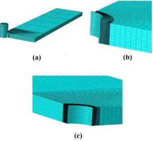
Fig. 5 shows a quarter of the 3D finite element model and some details of the assembly components. A linear elastic model was used for the sleeve with a young’s modulus of 210GPa and Poisson’s ratio of 0.3. The mandrel was modeled as a rigid surface, using the revolution feature of ABAQUS. Frictionless conditions were assumed between the mandrel and sleeve and between the sleeve and the aluminum alloy plate. The assumption of frictionless contact is justified because the sleeve is lubricated. The plate shown in Fig. 5a has 22130 3D hexahedral linear elements for the aluminum plate. The sleeve shown in Fig. 5b has 600 elements. Ten elements along the plate thickness were used. Previous works [10, 11] have shown that considerable mesh refinement on the surface of the plate and in the vicinity of the edge of the hole (Fig. 5c) is required. The hole expansion sequence takes place in two phases: in phase one a dynamic step is employed to ensure that mandrel is completely pulled out. Following the dynamic step, a static step without any external load is employed to ensure that the part is in equilibrium state. Fdinally, residual stresses are calculated using the ABAQUS software.
4. Crack closure analysis
Crack closure analysis was performed using the Gozin and Aghaie-Khafri [14] method. This method consisted of monitoring the displacement of a node during a loading cycle. The opening load is found when the displacement of the monitored node became positive during the loading stage of a load cycle. The closing stresses are found when the displacement of this node falls to zero during the unloading stage. Usually two load cycles are employed before crack opening measurement. The schematic of this procedure is indicated in Fig.6.
Fig.6 Loading cycle and crack opening measurement.
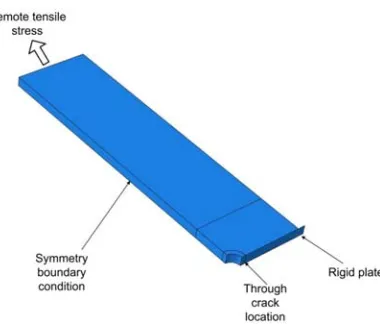
The first node behind the crack tip was used for the analysis. It is worth mentioning that a rigid plate (with size of 50mm × 6.35 mm) in the plane of the crack face is placed to prevent crack faces penetration (Fig. 7).
Fig. 7 Crack closure model.
April 2014 IJMF, Iranian Journal of Materials Forming, Volume 1, Number 1 5. Results and Discussion
5.1. Distribution of the residual stress: Effect of material behavior
3D modeling is capable of the prediction of the residual stress field through the plate thickness. The actual cold working process was modeled based on Carlson’s experiments [7] that consisted of 3.68% of interference. The calculated residual stress contours are shown in Fig. 8.
Fig. 8 Residual stress contour plots extracted from ABAQUS; (a) EPP model, (b) IH model, (c) KH model and (d) three paths that are used for the residual stress calculation.
The residual stress distributions for the entrance, mid-thickness and exit faces are shown in Fig. 9.
Stress variations through the part thickness highlight the importance of using 3D FEM for residual stress analysis. Concerning the entrance face, the distribution of radial and circumferential residual stress is highly dependent on the applied material model. The EPP model results in higher radial residual stresses and isotropic hardening behavior has second priority. The maximum tensile residual stress of 105MPa in the EPP model occurs from the 1.5mm to the hole edge (entrance face). While, for IH and KH models the maximum tensile residual stresses are 25% and 55% lower than the EPP model, respectively. At the mid-thickness the radial residual stresses are relatively lower than other sections (-50MPa to +20 MPa). Finally, at the exit surface for all three models the initial residual stress is zero and then changes to -240MPa at about 6mm distance to the hole edge.
EPP model and the IH model indicate the maximum compressive residual stress of -230MPa at the exit surface. Considering the KH model this value is -170MPa at the 2.5mm distance to the hole edge.
Considering close results that are shown in Fig. 9, the following conclusions can be made. Residual stress formation depends on the elastic modulus and the yield stress. For three material behaviors mentioned in section 2, the elastic modulus is identical.
Fig. 9 Results for the residual stress field obtained with different material models. (a) Radial (a1) entrance face; (a2) mid-thickness; (a3) exit face; and (b) circumferential (b1) entrance face; (b2) mid-thickness; (b3) exit face residual
stresses fields.
The yield stress at the first cycle for the isotropic hardening and elastic perfectly plastic models is identical. Besides, at the first loading sequence the kinematic hardening model also indicates the same yield stress. The difference between these models occurs following the yield stress where the EPP model indicates no change in stress, the IH model indicates work hardening and in the KH model a yield stress shift is expected. It is worth noting that in the cold expansion process just one loading-unloading cycle is applied. Thus, these models show no significant differences. In fatigue life simulation, considerable loading-unloading cycles employed and the material model behavior is more effective. Moreover, near the hole area the radial residual stress tends to be zero as a result of traction free surface at the bore. Thus, the magnitudes of the radial residual stress at this region are close to each other.
April 2014 IJMF, Iranian Journal of Materials Forming, Volume 1, Number 1 Considering the effect of cold work percent on the residual stress distribution, three models with
interferences of 2%, 3.68% and 5% were simulated using different mandrel sizes. In these simulations only the kinematic hardening behavior was considered. The results are indicated in Fig. 10.
Fig.10. The influence of the cold work interference on the residual stress field based on the kinematic hardening model. (a) Radial (a1) entrance face; (a2) mid-thickness; (a3) exit face; and (b) circumferential (b1) entrance face;
(b2) mid-thickness; (b3) exit face residual stresses fields.
compressive residual stress point. At the exit surface, radial stress calculation indicates that 2% interference maximum compressive residual stress is one time lower than 3.68% and 5% interferences. At this region some oscillations observed in the circumferential residual stress for 3.68% and 5% interferences. These oscillations are caused as a result of high plastic deformation at this region. In practice, following the hole expansion process, a reaming step is applied to eliminate these imperfections.
The radial residual stress distribution at the exit face is the same as the entrance face where
3.68% and 5% interference results in higher amount of compressive residual stress.
Circumferential residual stress distribution for 2% and 3.68% interferences are approximately the
same. However, for 5% interference some variations in results are observed.
It can be concluded that increasing the amount of cold work from 2% to 3.68% would result
in higher amount of compressive residual stress. But, more increase in cold work doesn't does
not result in significantly higher residual stress.
5.3. Crack opening loads: effect of material behavior and tensile load
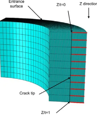
The crack opening load results are plotted against the crack tip node location which is defined at
Fig. 11.
Fig. 11 Crack tip node location definition.
The calculated normalized crack opening load results for through crack length are shown in Figs. 12 and 13. Fig. 12 is incorporated for the effects of material behavior and tensile load and Fig.13 contributes to the effects of the cold work interference and crack length.
April 2014 IJMF, Iranian Journal of Materials Forming, Volume 1, Number 1 Fig.12. Crack opening values with different material
modeling behavior and tensile loads.
Fig.13. Crack opening values with different cold work interference and crack length.
distribution depends on the material model behavior while at the exit surface obtained results are close to each other.
Increasing tensile stress to 120MPa results in normalized opening loads lower than 1.0 at all crack portions. This issue leads to higher crack growth rates and lower fatigue life. The effect of material model behavior at 120MPa is lower than 90MPa tensile stress. EPP and IH results are almost the same with 5% difference and KH results are 5% higher than IH at the first 5 nodes. The difference decreases at node numbers of 6-11. At 150MPa tensile load sequence, much lower crack opening values are observed. The maximum normalized crack opening is observed at the mid-thickness of the part using the isotropic hardening material model.
Fig. 13 shows the normalized opening loads for different cold work interferences and crack lengths. Three interferences of 2%, 3.68% and 5% were simulated at crack lengths of 1.6mm, 2.0mm and 2.5mm. The results obtained indicate that both parameters would affect the normalized opening load. At 1.6mm and 2.0mm crack length, 2% cold work interference indicates the highest averaged normalized opening load values through the part thickness and 3.68% and 5% interferences show close results. At 2.5mm crack length, 2% and 3.68% interference models illustrate same results while 3.68% model is higher. At this crack length, 5% interference model results in the lowest normalized opening values with an average of 0.59. Total average of normalized crack opening loads at crack lengths of 1.6, 2.0 and 2.5mm are 0.712, 0.714 and 0.7, respectively. Variation of normalized crack opening loads for interference of 2% at this crack length range is small with a range of 0.78-0.84. This variation is 0.68-0.76 and 0.54-0.60 for 3.68% and 5% interferences, respectively. It is worth noting that minimum opening values are observed for 5% cold work which is in contrast to the initial expectation. This issue can be contributed to crack lengths at which the crack closure analysis was performed. Considering the residual stresses distribution at crack lengths of 1.6-2.5mm (Fig. 10), it can be understood concluded that the highest absolute compressive residual stress at this region occurs for cold work interference of 2%. This issue leads us to conclude that the cold work interference and the crack lengths interact with each other and the fatigue life is a function of both parameters. None of them can independently indicate the fatigue behavior of a specimen.
6. Conclusion
Split sleeve hole expansion process was simulated using 3D finite element method. Residual stress distributions with different material behavior model and cold work interference were determined. Furthermore, parts with different cracks were considered. Then, various tensile loads were applied and normalized crack opening load was analyzed based on the crack closure method. The following conclusions can be drawn from the analysis.
1. 3D finite element modeling of the hole expansion process (Mandrel, sleeve and part) results in a better understanding of the residual stress distribution.
2. The nature of the material behavior model affects the residual stress distribution specifically at the entrance surface of the mandrel during the cold work process.
3. Considering entrance surface, the kinematic hardening model calculates superior radial and circumferential residual stress than the isotropic hardening model.
4. Increasing the cold work interference from 2% to 3.68% percent highly affects the distribution of the residual stress. However, the increasing to 5% slightly changes the amount of residual stress.
April 2014 IJMF, Iranian Journal of Materials Forming, Volume 1, Number 1 kinematic hardening model predicts the highest values of opening load at low remote tensile stress
levels.
6. Normalized opening loads are sensitive to the tensile remote stress and deceases with increasing of the applied load.
7. Despite the amount of cold work, 2% interference model illustrates the highest opening values especially at crack lengths of 1.6mm and 2.0mm.
8. Opening load analysis illustrates that crack closure depends on both cold work percentages and crack lengths and these two factors interact with each other.
7. References
[1] J.P. Gallagher, F.J. Giessler, A.P. Berens. USAF Damage tolerance design handbook: Guidelines for the analysis and design of damage tolerant aircraft structures. USAF systems command, Wright-Patterson Air Force
Base, OH, USA, 1984
[2] FTI, Cold Expansion Holes Using the Standard Split Sleeve System and Countersink Cold Expansion, Fatigue Technology Inc., Seattle, WA, USA, 2002.
[3] FTI, Extending the Fatigue Life of Metal Structures, Materials Testing, Fatigue Technology Inc., Seattle, WA, USA, 1991.
[4] P.M.G.P. Moreira, P.F.P. de Matos, S.T. Pinho, S.D. Pastramˇa, P.P. Camanho, P.M.S.T. de Castro, The residual stress intensity factors for cold worked cracked holes: a technical note, Fatigue and Fracture of Engineering Material and Structures, 27 (2004) 879-886.
[5] P.F.P. De Matos, P.M.G.P. Moreira, P.P. Camanho, P.M.S.T. de Castro, Numerical simulation of cold working of rivet holes, Finite Element in Analysis and Design , 41 (2005) 989-1007.
[6] W. Elber, Fatigue crack closure under cyclic tension, Engineering Fracture Mechanics, 2 (1970) 37-45.
[7] S.S. Carlson, Application of beta corrections to model and predict fatigue crack growth at cold expanded holes in 2024-T351 Aluminum alloys, M.Sc. Thesis, University of Utah, 2008.
[8] B. Clausen, M.B. Prime, S. Kabra, D.W. Brown, P. Pagliaro. Residual stress and plastic anisotropy in indented 2024-T351 aluminum disks, Proceedings of the SEM Annual Conference and Exposition on Experimental and Applied Mechanics, (2009) 1639-1646.
[9] J. Lemaitre, J.L. Chaboche,. Mechanics of solid materials, Cambridge University Press, Cambridge, 1990. [10] M.J. Pavier, C.G.C. Poussard, D.J. Smith, A finite element simulation of the cold working process for fastener holes, Journal of Strain Analysis for Engineering Design , 32 (1997) 287-300.
[11] M.J. Pavier, C.G.C. Ponssard, D.J. Smith, Finite element modeling of the interaction of residual stress with mechanical load for a crack emanating from a cold worked fastener hole, Journal of Strain Analysis for Engineering Design, 33 (1998) 275-289.
[12] M.J. Pavier, C.G.C. Poussard, D.J. Smith, Effect of residual stress around cold worked holes on fracture under superimposed mechanical load, Engineering Fracture Mechanics , 63 (1999) 751-773.
[13] E.W. O’Brien, Beneficial residual stress from the cold expansion of large holes in thick light alloy plate,
Journal of Strain Analysis for Engineering Design , 35 (2000) 261-276.
![Fig. 1. FTI's split sleeve expansion process [2].](https://thumb-us.123doks.com/thumbv2/123dok_us/8956299.1865667/2.612.146.465.253.409/fig-fti-s-split-sleeve-expansion-process.webp)