www.geosci-instrum-method-data-syst.net/3/201/2014/ doi:10.5194/gi-3-201-2014
© Author(s) 2014. CC Attribution 3.0 License.
The origin of noise and magnetic hysteresis
in crystalline permalloy ring-core fluxgate sensors
B. B. Narod1,2
1Narod Geophysics Ltd., Vancouver, Canada
2Department of Earth, Ocean and Atmospheric Sciences, University of British Columbia, Vancouver, Canada Correspondence to: B. B. Narod (bnarod@eos.ubc.ca)
Received: 19 March 2014 – Published in Geosci. Instrum. Method. Data Syst. Discuss.: 19 June 2014 Revised: 17 August 2014 – Accepted: 26 August 2014 – Published: 29 September 2014
Abstract. Developed in the 1960s for use in high-performance ring-core fluxgate sensors, 6–81.3 Mo permal-loy remains the state of the art for permalpermal-loy-cored fluxgate magnetometers. The magnetic properties of 6–81.3, namely magnetocrystalline and magnetoelastic anisotropies and sat-uration induction, are all optimum in the Fe–Ni–Mo system. In such polycrystalline permalloy fluxgate sensors, a sin-gle phenomenon may cause both fluxgate noise and magnetic hysteresis; explain Barkhausen jumps, remanence and coer-civity; and avoid domain denucleation. This phenomenon, domain wall reconnection, is presented as part of a theoret-ical model. In the unmagnetized state a coarse-grain high-quality permalloy foil ideally forms stripe domains, which present at the free surface as parallel, uniformly spaced do-main walls that cross the entire thickness of the foil. Leakage flux “in” and “out” of alternating domains is a requirement of the random orientation, grain by grain, of magnetic easy axes’ angles with respect to the foil free surface. Its magne-tostatic energy together with domain wall energy determines an energy budget to be minimized. Throughout the magneti-zation cycle the free-surface domain pattern remains essen-tially unchanged, due to the magnetostatic energy cost such a change would elicit. Thus domain walls are “pinned” to free surfaces.
Driven to saturation, domain walls first bulge then recon-nect via Barkhausen jumps to form a new domain configu-ration that I have called “channel domains”, which are at-tached to free surfaces. The approach to saturation now con-tinues as reversible channel domain compression. Driving the permalloy deeper into saturation compresses the channel do-mains to arbitrarily small thickness, but will not cause them to denucleate. Returning from saturation the channel domain
structure will survive through zeroH, thus explaining rema-nence. The Barkhausen jumps, being irreversible exothermic events, are sources of fluxgate noise powered by the energy available from domain wall reconnection.
A simplified domain energy model can then provide a pre-dictive relation between ring-core magnetic properties and fluxgate sensor noise power. Four properties are predicted to affect noise power, two of which are well known: saturation total magnetic flux density and magnetic anisotropy. The two additional properties are easy axes alignment and foil thick-ness. Flux density and magnetic anisotropy are primary mag-netic properties determined by an alloy’s chemistry and crys-talline lattice properties. Easy axes alignment and foil thick-ness are secondary, geometrical properties related to an al-loy’s polycrystalline fabric and manufacture. Improvements to fluxgate noise performance can in principle be achieved by optimizing any of these four properties in such a way as to minimize magnetostatic energy.
Fluxgate signal power is proportional toB−Hloop cur-vature [d2B/dH2]. The degree to which Barkhausen jumps coincide with loop curvature is a measure of noise that ac-companies the fluxgate signal.B−H loops with significant curvature beyond the open hysteresis loop may be used to advantage to acquire the fluxgate signal with reduced noise.
1 Introduction
a low-noise magnetic alloy now referred to as 6–81.3 Mo permalloy, or simply “6–81” (http://www.magson.de/ technology/tech3.html) (Gordon et al., 1968). Answering the question of why 6–81.3 Mo permalloy became the de facto standard for low-noise ring-core fluxgates is the first motiva-tion for this paper.
I begin with an examination of data that relate fluxgate noise to various physical parameters and provide evidence that the geometric configurations of a fluxgate’s magnetic material are significantly more important than Gordon’s in-vestigators may have thought. As surface area – either free surface or intergrain – of the magnetic material increases, so does the fluxgate noise power. This suggests there is a causal link between fluxgate noise and magnetostatic energy by way of domain wall energy, and that all are fundamentally depen-dent on the properties magnetic moment and anisotropy.
Amos et al. (2008) using magnetic force microscopy (MFM) have shown that sputtered permalloy films assume configurations called “stripe domains”. Thus it should be beneficial to examine the causes of stripe domains. Since fluxgate sensor function requires periodic core saturation in order to generate a signal, it is also beneficial to study the evolution of stripe domains throughout the magnetization cycle.
Recently, Coïsson et al. (2009), also using MFM, deter-mined the surface expression of stripe domains in sputtered films throughout the magnetization cycle, confirming con-straints on magnetostatic energy which can be derived from simple principles. I propose that, on approach to saturation, each stripe domain undergoes a well-defined, exothermic and irreversible transition to a saturated state, with domain wall loss supplying the energy. It further follows that these transitions could be used to explain many aspects of irre-versible and reirre-versible magnetization processes in magnet-ically soft materials, in particular DC coercivity, remanence and hysteresis.
Fluxgate noise and DC hysteresis are thus arguably two facets of the same phenomenon, and fluxgate sensor noise is causally tied to domain wall energy by a simple relationship: fluxgate noise is proportional to available domain wall en-ergy, which itself is a function of domain size and domain wall energy density.
Magnetocrystalline anisotropy complicates the story: in any polycrystalline permalloy, each crystal assumes an easy axis from a distribution, an axis that in general will not lie parallel to the magnetizing field, nor to the free surface. This affects domain size and local magnetization processes. Satu-ration transitions in one crystal will not in general coincide with those in any other crystal. Fluxgate noise and a ferro-magnet’s path to saturation will be an aggregate of all the in-dividual crystals’ processes. But the basic phenomena can be understood by examining processes in a single, ideal crystal.
!" #!" $!" %!" &!" '!"
#" %" '" (" )" ##" #%" #'" #(" #)" $#" $%" $'"
*+
,-./"
0+1/2"345"6789.:;"<"#:;"
Magnetics 12µm 4-79"before" Magnetics "after 100/100"
Figure 1. Histograms of noise power for 4–79 permalloy ring cores.
2 Magnetic properties of 6–81
The original choice of 6–81 followed on the work of Pfeifer (1966) and Pfeifer and Boll (1969), who presented data which showed that 6–81 has near-zero polycrystalline magnetostriction and magnetocrystalline anisotropy for very slow cooling. The higher molybdenum content of 6–81 has additional useful aspects, the first of these being a lower sat-uration total magnetic flux densityBs, now known to directly affect the noise power level of a magnetometer. The first in-dications that lowerBsled to lower fluxgate noise were pro-vided by Shirae (1984) and Narod et al. (1985), both using selections of amorphous alloys.
Another useful aspect to using 6–81 is its need for very slow cooling rates to achieve low anisotropy. While the added furnace operating time is a significant processing cost, it re-sults in lower average noise power levels, as compared with those for a rapidly cooled alloy such as 4–79 permalloy. Fig-ure 1 presents the results from this author’s own study of 167 Magnetics Inc. 4–79 ring cores with properties other-wise similar to Infinetics S-1000 6–81 ring cores. These rings were made from 4–79 square loop permalloy, with seven lay-ers each 12 µm thick. The white histogram shows the noise power probability density function (PDF) for the rings as received from their original heat treatment. The black his-togram shows the noise power PDF for the same rings af-ter they had all received an extra heat treatment of 100 h at 100◦C in air. Note the general shift of the density function towards lower noise levels. Figure 2 shows a similar prob-ability density function for a collection of 195 as-received 6–81 ring cores (12 µm), a function which also exhibits an asymmetric form. These data suggest that 6–81’s require-ment for slow cooling acts as a substitute for the beneficial low-temperature heat treatment.
!" #" $" %&" %'" &!"
!" (" '" )" %&" %*" %$" &%" &#"
+,
-.
/0"
1,203"456""789:/;<"="%;<"
>.?.3@A0"%&BC" >.?.3@A0"(BC"
Figure 2. Histograms of noise power for 6–81 permalloy ring cores.
in the Fe–Ni–Mo ternary system. These properties can now provide clues to the nature of fluxgate sensor noise.
3 Geometrical evidence towards a theory of noise Two more observations provide evidence for the last clues needed for a theory of noise. Figure 3 shows dB/dt vs.t plots, an analog for DC differential permeability vs. H for five ring cores, two of material 6–81 and three of 4– 79 permalloy, each annotated with its noise power. Lower noise power correlates with higher peak dB/dt. Similarly amorphous alloys treated at temperatures up to 350◦C will develop large magnetic domains (Shishido et al., 1985), and treating such alloys to about 300◦C will significantly reduce their noise power (Narod et al., 1985). The 4–79 rings exhibit both higher noise power and higher coercivity (peaks are to the right of the 6–81 curves). This is likely a grain size effect (Pfeifer and Radaloff, 1980).
A hypothesis follows: (1) larger domain sizes lead to both lower noise and to higher differential permeability, and (2) smaller grain size leads to higher domain wall energy, noise power and coercivity. It then follows that total domain wall area is also related to fluxgate sensor noise.
A last clue comes from my examination of noise in a large collection of Infinetics 6–81 ring cores. This included 195 12 µm rings with 7 layers each, and 75 3 µm rings with 28 layers. Otherwise these rings are similar. Figure 2 shows the noise PDFs for this collection, with 3 µm rings’ data in white, and 12 µm data in black. Counts have been scaled to match. These data clearly show that the 3µm rings are typ-ically 12 dB noisier than the 12 µm rings. Equally, the 3 µm rings have 4 times the free-surface area, which is the same ratio. With such a large number of specimens, from a large number of independent processing batches, this statistic is robust and cannot have happened by chance. Clearly the ge-ometry of the fluxgate core material matters, and any theory of fluxgate noise must be able to take this into account.
0!
20!
40!
60!
80!
100!
120!
0.75! 1.00! 1.25! 1.50! 1.75! 2.00!
mV
!
Time (ms)!
INF-Q!
INF-2!
M331-70!
M331-49!
M331-104! 4-79
5 pT
21 pT 23 pT
40 pT 16 pT
6-81
d
B
/d
t
(a
rb
itr
a
ry
u
n
its
)
Figure 3. dB/dtplots for 6–81 and 4–79 ring cores. Noise values
are in pT rtHz−1at 1 Hz, for this insert and all other data in this paper.
4 TheB−H curve from a fluxgate’s point of view Consider a ring core lying in the plane of this page, immersed in a small external fieldHe(Fig. 4), with core drive fieldHd; internal flux densityB. Consider a volume elementA−A0, comprising two mirror-symmetric elements 180◦ apart on the ring and located whereHe is parallel toHd. Locally at pointA,BisB(Hd+He) and atA0 B isB(Hd−He). As viewed from a sensor winding parallel toHe, their combined flux density is
1B (Hd)=B (Hd+He)−B (Hd−He)=He
dB dHd
. (1)
This requires that one superpose the ring’s response toHd andHe (Primdahl et al., 2002). He is not necessarily uni-form. It can vary both spatially and temporally. Open-circuit sensor windings avoid temporal changes, while short-circuit or capacitively loaded sensors causeHe to vary throughout the saturation cycle.
Moving up the B−H curve by an amount ∂Hd, the change in flux density as seen by the sensor winding is
1B (Hd+∂Hd)−1B (Hd)=∂HdHe
d2B
dHd2. (2)
The rate of change of flux density with time is then dB
dt =He d2B dHd2
dHd
dt . (3)
Similarly, for a general volume elementC−C0, one takes into accountB−Hmisalignment. To calculate energy avail-able to the sensor winding per cycle, one needs to multiply dB/dtbyHe, and integrate over volume and time:
energy= Z
T
Z
V d2B dHd2
·He
!
dHd dt ·He
Thus fluxgate sensitivity results from the second derivative of theB−H curve, i.e., its curvature. Actual power trans-fer goes as the product of B−H curvature and the rate of change of the drive field. The importance of the sec-ond derivative was originally noted by Marshall (1966) and Primdahl (1970).
5 A theory of noise
To understand how saturation can cause both signal and noise, it is necessary to examine the processes that govern the formation and evolution of the ring’s magnetic domains. For an idealized iron crystal, Fig. 5a–d respectively represent a demagnetized ring core, a core immersed in an external field, a core partially magnetized by an excitation field and a core saturated by an excitation field. Each sector representation (a–c) comprises two domains jointly bounded by a common 180◦domain wall. In Fig. 5a the core is depicted as having equal opposed domain paths, with zero net magnetization.
In an external fieldH(Fig. 5b), only sectors with magne-tization directions parallel toHrespond. A sensing winding develops a self-inductance higher than for a saturated core, and can generate the fluxgate signal as described above. In Fig. 5c an excitation field has the domain path assisted by the excitation field expand, consistent with the high effec-tive permeability one expects in a toroidal magnetic circuit. Here the effects of the excitation and external fields are en-tirely separable with the excitation field occupying a toroidal, low-reluctance circuit and the external field response occupy-ing a solenoidal, high-reluctance circuit. Perfect separability also manifests as zero mutual inductance between the two magnetic circuits. At saturation (Fig. 5d), both ferromagnetic paths vanish, and inductances fall to air-core values (Butta and Ripka, 2008).
Figure 5 is not useful for considering domains in poly-crystalline permalloys. I present here a hypothetical hystere-sis and noise model based on stripe domains. Here domains have uniform widthD, occupy the entire thicknesst of the film (or foil, or grain), and have lengths that are large com-pared to either width or thickness. TypicallyDandt are of the same magnitude, withD < t, except for very thin films. Figure 6 extends the concepts of Fig. 5 to examine a small portion of a core, within a single crystal – one that occupies the entire thickness of the core foil material.
Areal domain wall energy density can be approximated as
Ed=2π
s
J S2K
a ∝2π
s
B2
sK
a . (5)
K is a parameter representing all of magnetic anisotropy,J is the exchange integral, S is the magnitude of atomic spin anda is the lattice constant (Chikazumi, 1997).Bs2 is pro-portional to J S2given thatJ is proportional to Curie tem-perature Tc (Weiss, 1948), Tc is proportional to magnetic
moment-squaredM2(Chikazumi, 1997, Eq. 6.8), andBs cor-relates strongly withM(see Sect. 7 below). The substitution withBsrequires the assumption that face-centered cubic lat-tice parameters, spin magnitude and molecular field coeffi-cient vary little or not at all compared with variation inBs over the range of permalloy compositions.
Magnetic anisotropy for cubic alloys has higher order terms. Reducing anisotropy to a single parameter, however, does not significantly impact our aim, which is to calcu-late total domain wall energy and total magnetostatic en-ergy, and minimize their sum in order to determine domain width. Magnetostatic energy is required on the free surface of a permalloy foil as all crystalline permalloys have nonzero anisotropy and an easy axis that dips across the free surface at some angleα. Flux density across the free surface is thus aboutα Bs, where a small angle is assumed forα. Figure 6 indicates the associated flux paths as curved arrows originat-ing from one domain and returnoriginat-ing to an adjacent domain.
For soft magnetic materials the calculation is slightly more complicated, with three energies to equilibrate: domain wall energyEd, magnetostatic energyEsand magnetic anisotropy energyEc. Assuming uniform spin rotation and neglecting free-surface depolarization, these energies (per unit volume) are
Ed∝2π
p
B2
sK/a
D ; Es=(βBs)
2 D
t µo
Ec=(α−β)2K, (6)
whereβis the actual magnetization dip angle with respect to the free surface. Similar to the approach taken in Butta and Ripka (2008), the total energy is minimized whenEdequals Esand when the dip angle is
β=α 1
1+D
t B2
s
Kµo
. (7)
For the thick foils used in typical ring cores the two angles become equal, and D is proportional to t1/2. In this case Ec vanishes and the equilibrium approaches that derived by Kittel (1949). In Amos et al. (2008), for films below 1 µm, a square-root relation betweenDandt held, implying a value forKsuch that the angleβ=α.
B
B
Hd
He He
A A'
C C'
θ
Hd
Hd+∂Hd
Hd+∂Hd±He
Hd±He
∆B(Hd)
∆B(Hd+∂Hd)
H B
Figure 4. Ring core schematic andB−H loop detail.
a b c d
H
H H
Figure 5. Ring-core domains: responses to external or excitation
fields: (a) a demagnetized ring core; (b) a ring core exposed to external fieldH, depicting enhanced domains with magnetization parallel toH; (c) a ring core exposed to a drive fieldH, depicting enhanced domains with magnetization parallel toH; (d) a ring core exposed to a saturating drive fieldH, depicting single domains with magnetization parallel toH.
α
D
magne
tostatic
surface
energ
y
t
to edges
Figure 6. Detail of stripe domains in a demagnetized core. Thin
ar-rows depict magnetic flux – the larger, vertical arar-rows indicating the dominant flux internal to the core, and the looped arrows depicting the smaller but significant flux crossing the free surface.
to the longer arc length of the domain wall across the foil thickness.
Increasing the applied field further expands the domain wall (Fig. 8a). Eventually a field value is reached where adjacent domain walls make contact (Fig. 8b), at which point a domain wall reconnection occurs (Fig. 8c), form-ing a new configuration in which a pair of arched domains
Figure 7. Domain wall motion for initial permeability.
a b
c d
Figure 8. Stripe and channel domain configurations.
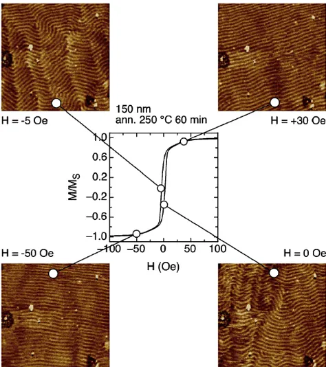
Figure 9. Hysteresis loop of the 150 nm thick film annealed at
250◦C for 60 min. Selected MFM images are shown, which are taken at different applied field values. The corresponding point of the hysteresis loop is indicated (Coïsson et al., 2009). (Non-SI units are in the original publication: 1 A m−1∼=0.0126 Oe.) The speci-men was a sputtered FeSiB amorphous film. Reproduced with per-mission of the copyright owner.
stripe domains. However the free-surface expression of the channel domains remains, and the domains themselves can-not denucleate.
In Coïsson et al. (2009), Fig. 4 (here as Fig. 9) provides evidence for the formation of channel domains. MFM im-ages of the domains’ surface expressions for the two po-larizations of a saturated specimen are practically indistin-guishable, and substantiate the strength of the magnetostatic energy boundary condition. (To be clear, in crystalline al-loys, the stripe domains would form due to magnetocrys-talline anisotropy and not spin reorientation (Coïsson et al., 2009; Sharma et al., 2006). Their test material was an iron-metalloid-sputtered film, but arguably the magnetostatic en-ergy constraints should be similar.)
The saturated state is thus one of the channel domains, which, being shallow and bounded by a free surface, are rel-atively difficult to compress (low permeability). The demag-netized state is dominated by stripe domains. Walls are rela-tively easy to move, and reconnections manifest as large val-ues of differential permeability (Barkhausen jumps). In gen-eral the distribution of individual crystals’ easy axes will be random. This results in a range of H values for which re-connections will occur in a bulk specimen, and any attempt
Figure 10. Expanding channel domains.
to estimate differential permeability will need to take this into account. The return from saturation starts by expanding the channel domains, similar to inflating a bubble (Fig. 10). Channel domains self-align across the thickness of the foil, due to the transverse magnetic moments of the channels having opposing magnetic charges, attracting each other by means of a mechanism broadly similar to one found by O’Brien et al. (2009) for transverse domains in permalloy nanowires. Initially the domain walls extend slowly, requir-ing a lot of variation inH for relatively little gain in netB, hence the slowly changing but accelerating tops of the hys-teresis curve. The channel domains begin to expand, adding domain wall area and requiring energy to do that – the energy of hysteresis. Eventually the channels themselves reconnect via a second, smaller Barkhausen jump to again form stripe domains, and then the process repeats, now in the opposing polarity. For stripe domains reconnecting into channels, a lot of domain wall energy is released. For channel domains con-verting to stripes, the amount of energy available is much less clear. The field value at which this occurs is likely closely re-lated to what we can observe as coercivityHc.
Using Eqs. (6) and (7), solving for and eliminatingD, one finds that for a demagnetized stripe domain system, domain wall energy per unit volume is proportional to
Ed∝t−1/2×α×Bs3/2×K1/4. (8)
6 Putting it to the test
Two of the four parameters given in Eq. (8), Bs and anisotropy, are well known to be involved in producing flux-gate noise. With Marc Lessard and others at University of New Hampshire, I have put foil thickness as a controlling parameter to the test by making 6–81 ring cores that differ from the Infinetics design only in foil thickness. We pro-duced two groups of rings, one with one layer and the other with seven layers, as follows: cast an ingot of 6.0 % Mo, 81.3 % Ni, Fe balance. Fabricate flat strips approximately 3 mm×25 mm×125 mm. Homogenize at 1100◦C in 95 % Ar/5 % H for 7 days. Cold-roll to 100 µm, with no in-process anneal. Slit to width. Coat with a thin layer of MgO. Spot-weld to an Inconel X750 bobbin. Heat treat in 95 % Ar/5 % H for 4 h at 1100◦C, cool to 600◦C, and then cool at 35◦C h−1 to room temperature. At no point during this development was any attempt made to optimize a process step. This was simply our first attempt to fabricate a 6–81 polycrystalline permalloy ring core.
Noise PSD at 1 Hz for the two types of 100 µm rings are 14 and 5.2 pT rtHz−1, respectively, the difference con-sistent with root-mean-square stacking. Figure 11 presents theB−H curves for these and Infinetics 3 and 12 µm rings, measured at 25 Hz. All four rings were assembled with 25.4 mm diameter bobbins.B−Hcurves were collected us-ing primary and secondary windus-ings of 10 turns each. Each core and a current sense resistor forH were driven by a tri-angular current source peaking at±110 A m−1. ForB, sec-ondary signals passed to an operational amplifier configured as a high-input-impedance integrator.
The magnetic material was 6–81 in all cases, and heat treatments were nominally identical. The 100 µm ring has a single layer and the 400 µm ring has a single circular wire of diameter 400 µm. The magnetic masses of the four rings match within 20 %, allowing theB−H curves to be recorded without any changes to the measurement settings. Between measurements, only the ring was changed. Coer-civities for the four rings are in the range 3–7 A m−1. 6.1 Another look atB−H loop curvature
Infinetics thin foils develop high differential permeability and more square B−H curves. The 100 µm rings exhibit much “rounder” curves and lower remanence, yet have excel-lent noise performance. In fact, the new seven-layer rings at 5.2 pT are amongst the best performing permalloy ring cores ever produced. How roundB−Hcurves improve noise per-formance requires a further development of the noise model. Referring now to Fig. 11c, from point A to point B there is little curvature, so little or no power is transferred to the sensor winding. Changes in B are dominated by large Barkhausen jumps which are identified in the noise model with domain wall reconnections from stripes to channels. All the energy released by these events couples back into the
Figure 11. Top panels: Infinetics 12 and 3 µmB−H curves.
Bot-tom panels: 6–81 100 and 400 µm. The drive field is±110 A m−1, a triangle waveform at 25 Hz to approximate DC behavior. The in-set for (c) presents a digitally acquired detail of the distinct transi-tion from irreversible behavior to reversible behavior. The argument presented here is that there are no Barkhausen-jump-related losses above the transition point, and that the large variation inBabove the transition point requires reversible domain wall motion in the form of channel domain compression.
Hd drive circuit and no noise energy gets into the sensor winding.
From B to D, curvature is larger, reaching a maximum at point C. Over this interval, energy is transferred to the sensor winding. Since changes inBare still dominated by stripe-to-channel reconnections in this range, it is here that fluxgate noise power is generated, ending at D, just beyond closure of the hysteresis loop. From D to E, changes inBcan result from domain wall movement in the form of channel domain compression. Our new ring cores exhibit significant curva-ture in this range, resulting in its roundB−H curve. This curvature generates additional sensor energy, and since the process of channel domain compression is nominally a re-versible process, this additional sensor energy comes with little noise energy when compared with interval B–D.
(a) (b)
A
P A'
Figure 12. Channel domain sections: (a) thin foils and (b) thick
foils.
and clearly this is not the case. Reversible rotation on its own would require an average easy axis misalignment of 45 % to explain the 30 % reversible approach to saturation in Fig. 11c. This is unlikely, implying a need for reversible domain wall motion.
From E to D and partway to point F, an interval of channel domain expansion, energy may be recaptured from the sensor winding. From D to F theB−Hcurve is dominated by small Barkhausen jumps which can be identified with channel-to-stripe reconnections (Chikazumi, 1997, Fig. 18.43). From point F to point G the B−H curve is again of low cur-vature, dominated by large Barkhausen jumps (stripe-to-channel reconnections).
The channel domain concept can also inform remanence variability in permalloy foils, and in particular why thin foils exhibit greater remanence. Remanence exists because chan-nel domain walls, while satisfying internal boundary condi-tions, do not lead to a symmetry such that net magnetization is zero.
Figure 12 displays the proposed channel domains for very thin foils (a) (or high anisotropy), or very thick foils (b) (or low anisotropy). For thin foils (Fig. 12a), at point P on chan-nel domain centerline sectionA−A0, the internal boundary condition requires at P thatH=0. The very wide aspect of the channel domain means that the field at P is mainly in-fluenced by a neighborhood dominated by relatively planar domain walls. This neighborhood is depicted as the dashed square. A simple calculation using oval channels leads to a remanence ratio estimate of 59 %, in rough agreement with theB−H curves in Fig. 11.
For thick foils the domains are larger, but their aspects are very different, appearing as thin or dense laminations. A point at the tip of a channel domain is influenced by a much smaller neighborhood. This is depicted in Fig. 12b as the small dashed square. Destructive interference causes ma-terial outside this square to have less influence. In the limit, as channels come close to touching, and using ovals to ap-proximate the domain shape, one obtains a remanence ratio of 21 %, a value found in many natural materials, and also in this study for the 400 µm material. Thicker foils thus reduce fluxgate noise in two ways, both of which reduce total power to the Barkhausen jumps. They reduce total domain wall en-ergy (Pfeifer and Boll, 1969), and deep channels reduce the range inBoccupied by the hysteresis loop.
Figure 13. Three-dimensional representation of a single grain and
stripe-to-channel reconnection. The left image depicts the unmag-netized stripe domains within a grain. A larger grain would contain additional domains, all of which the same width. The middle image depicts initial permeability. The right image depicts the start of re-connection at the domain wall midpoint. A fixed amount of domain wall displacement is required, regardless of the size of the grain. A larger grain would also have longer stripe domains and require less external field for a given amount of wall displacement, i.e., higher initial permeability. Higher initial permeability in combination with a fixed amount of wall displacement for reconnection implies lower coercivity. Thus increasing grain size leads directly to higher per-meability and lower coercivity.
6.2 Effects of grain size
In a determination by scanning electron microscopy, grain sizes of our new material are about 20 µm; thus there exists a large intergrain boundary area within the foil. Mismatch of easy axes at these interior surfaces also serves to localize magnetostatic energy, and if channel domains form at free surfaces, so too should they form at intergrain boundaries. This source of magnetostatic energy must give rise to addi-tional domain walls. Energy needed to reconnect the inter-grain channel domains back to stripes will manifest as an increase in hysteresis loss, and relates to the known inverse relation between grain size and coercivity (Couderchon et al., 1989; Herzer, 1990; Pfeifer and Radaloff, 1980). Speculat-ing further, if larger grains lead to longer magnetic domains then considered as a solenoid, each domain’s local field near its surface would decrease with increasing grain size. This implies that a given amount of domain wall displacement requires less drive field to achieve equilibrium, and by ex-tension that domain wall reconnections require less external field (Fig. 13). These are interpretable as higher initial per-meability and lower coercivity, respectively, both known to correlate with lower fluxgate noise (Nielsen et al., 2010).
7 Additional considerations
Equation (8) can be used to guide choices in magnetic materials and in ring-core geometry. Regarding the choice of material, 6–81 clearly has very desirable properties. To improve further we need to look for lower Bs materials while simultaneously maintaining low anisotropy. Within the quaternary system Fe–Ni–Mo–Cu, it is possible to esti-mate Bs by calculating an alloy’s average atomic moment: Bm=at % Fe·2.8+at % Ni·0.6−at % Mo·4.6−at % Cu
·0.4, and correlating that with Bs. Figure 14 summarizes such data. The open square marked “3” represents 6–81. The circle marked “6” represents Neumann’s “1040” alloy, which is a possible contender for an improved fluxgate core material due to its lowerBs.
Reducing magnetostatic energy by reducing free-surface area is an obvious method to reduce domain wall energy. The use of thicker foils or even wires is such a means, with both options being relatively easily achieved. Reducing intergrain surface area is also a means to reduce magnetostatic energy, which is to be achieved by the application of specific heat treatments tailored to growing large crystals. Ideally a typical grain would be the full thickness of the foil or wire and its diameter much larger. Cold forming to control for easy axis direction might also be an approach to further reduce domain wall energy.
8 Conclusions
I have presented evidence by means of both data and theory that noise power in the parallel-gated fluxgate has its origin in domain wall energy that transforms irreversibly and exother-mically to eddy current energy when domain walls recon-nect, identifiable with Barkhausen jumps. Domain wall en-ergy available for noise generation is maintained in a balance with magnetostatic energy, which, in thin foils, is dominated by the anisotropy-driven surface magnetostatic energies. Re-ducing surface area thus reduces noise energy.
Ed and thus fluxgate noise is reduced by treating the permalloy for low anisotropy. However the biggest influence onEdis the saturation total magnetic flux densityBs. Reduc-ingBssimultaneously reduces all energies. Its only limitation is a need to concurrently reduce Curie temperature.
These argue for the existence of a previously unidentified magnetic domain state that I have called “channel domains”. A channel domain hypothesis can be expressed as follows: in the presence of no external field, an individual crystal of a soft magnetic metal can assume one of three magnetized states. One state, in the form of stripe domains, has zero net magnetization. The second and third states, in the form of channel domains of different polarizations, have nonzero net magnetization. A stripe domain or a channel domain state can convert to the other by domain wall expansion and irre-versible reconnection – a large and small Barkhausen jump,
Figure 14. Saturation total magnetic flux density vs. average
atomic moment. Data are from Neumann (1934), von Auwers and Neumann (1935) or Bozorth (1993), or are calculated estimates. Large, open symbols represent alloys: (1) 14 % Cu, (2) mumetal, (3) 6–81, (4) 4–79, (5) supermalloy, (6) “1040”, and (7) 28 % Cu. Small symbols representBsdata for a range of ternary alloys.
respectively. The three states, one in the form of stripe do-mains and the other two in the form of channel dodo-mains, can satisfy nearly identical surface boundary conditions. The combination of crystals in a stripe domain state and those in a channel domain state is arbitrary and will depend on the his-tory of external fields. DC hysteresis results from the cycling between stripe and channel domain states via Barkhausen jumps.
Much work remains. Specimens need to be created which have much larger grain sizes than in existing materials. This will require heat treatments at higher temperatures and for longer durations than normally used for permalloys. Domain imaging of large-grain, low-anisotropy crystalline permal-loys throughout a magnetization cycle should provide fur-ther testing of the hypothesis. Combining domain imaging with the manipulation of final heat treatments could deter-mine the relations between anisotropy, domain sizes and fluxgate noise. Fabric analysis could provide data regarding easy axes alignments. Micromagnetic numerical simulations of stripe domain systems with pinned free-surface expres-sions could lead to understanding of the energetics of domain wall reconnections.
Acknowledgements. I thank J. R. Bennest, G. Cross, and S. Allegretto, who assisted with this manuscript. The Geological Survey of Canada made the collection of 6–81 ring cores available. I thank S. Kuyucak of CANMET; P. Dosanjh at UBC; M. Lessard and the others at UNH; and L. Jewitt, Laura K Jewitt Design Gallery, for their efforts in creating the new 6–81 ring cores.
Edited by: M. Díaz-Michelena
References
Amos, N. R., Fernandez, R., Ikkawi, R., Lee, B., Lavrenov, A., Krichevsky, A., Litvinov, D., and Khizroev, S.: Magnetic force microscopy study of magnetic stripe domains in sputter de-posited Permalloy thin films, J. Appl. Phys., 103, 07E732-1– 07E732-3, doi:10.1063/1.2835441, 2008.
Bertotti, G.: Connection between microstructure and magnetic properties of soft magnetic materials, J. Magn. Magn. Mater., 320, 2436–2442, 2008.
Bozorth, R. M.: Ferromagnetism, in facsimile, edited by: Perkins, W., IEEE Press, Piscataway, NJ, 1993.
Butta, M. and Ripka, P.: Two-Domain Model for Orthogonal Flux-gate, IEEE T. Mag., 44, 3992–3995, 2008.
Chikazumi, S.: Physics of Ferromagnetism, 2nd Edn., Oxford, Clarendon, 1997.
Coïsson, M., Vinai, F., Tiberto, P., and Celegato, F.: Magnetic prop-erties of FeSiB thin films displaying stripe domains, J. Magn. Magn. Mater., 321, 806–809, 2009.
Couderchon, G., Porteseil, J. L., Bertotti, G., Fiorillo, F., and Soardo, G. P.: Magnetization Process in NiFe Alloys with Van-ishing Anisotropies, IEEE T. Mag., 25, 3973–3975, 1989. Gordon, D. I., Lundsten, R. H., Chiarodo, R. A., and Helms Jr., H.
H.: A Fluxgate Sensor of High Stability for Low Field Magne-tometry, IEEE T. Mag., 4, 397–401, 1968.
Herzer, G.: Grain size dependence of coercivity and permeability in nanocrystalline ferromagnets, IEEE T. Mag., 26, 1397–1402, 1990.
Kittel, C.: Physical Theory of Ferromagnetic Domains, Rev. Mod-ern Phys., 21, 541–583, 1949.
Kuyucak, S.: Characterization of Permalloy Strip, Metals Technol-ogy Laboratories Report MTL 96-28, Natural Resources Canada, Ottawa, 1996.
Marshall, S. V.: Sensitivity of the Ring-Core Magnetometer, IEEE T. Mag., 2, 773, 1966.
Narod, B. B., Bennest, J. R., Strom-Olsen, J. O., Nezil, F., and Dun-lap, R. A.: An evaluation of the noise performance of Fe, Co, Si, and B amorphous alloys in ring-core fluxgate magnetometers, Can. J. Phys., 63, 1468–1472, 1985.
Neumann, H.: Neue magnetische Legierung “1040” mit hoher Anfangs-Permeabilität, Archiv Techn. Messen, Leiniz Verlag, München, 913–915, 1934.
Nielsen, O. V., Afanassiev, Y., and Fornaçon, K. H.: Magnetic Ma-terials for Sensors, in: Fluxgate Magnetometers for Space Re-search, edited by: Musmann, G., Books on Demand, Nordersted, 152–168, 2010.
O’Brien, L., Petit, D., Zeng, H. T., Lewis, E. R., Sam-paio, J., Jausovec, A. V., Read, D. E., and Cowburn, R. P.: Near-Field Interaction between Domain Walls in Adja-cent Permalloy Nanowires, Phys. Rev. Lett., 103, 077206, doi:10.1103/PhysRevLett.103.077206, 2009.
Pfeifer, F.: Zum Verständnis der magnetischen Eigenschaften tech-nischer Permalloylegierungen, Z. Metallkd., 57, 295–300, 1966. Pfeifer, F. and Boll, R.: New Soft Magnetic Alloys for Applica-tions in Modern Electrotechnics and Electronics, IEEE T. Mag., 5, 365–370, 1969.
Pfeifer, F. and Radaloff, C.: Soft magnetic Ni-Fe and Co-Fe alloys – some physical and metallurgical aspects, J. Magn. Magn. Mater., 19, 190–207, 1980.
Primdahl, F.: The Fluxgate Mechanism, Part I: The Gating Curves of Parallel and Orthogonal Fluxgates, IEEE T. Mag., 6, 376–383, 1970.
Primdahl, F., Brauer, P., Merayo, J. M. G., and Nielsen, O. V.: The fluxgate ring-core internal field, Measurement Sci. Technol., 13, 1248–1258, 2002.
Sharma, P., Kimura, H., Inoue, A., Arenholz, E., and Guo, J.-H.: Temperature and thickness driven spin-reorientation transition in amorphous Co-Fe-Ta-B thin films, Phys. Rev. B, 73, 052401-1– 052401-4, doi:10.1103/PhysRevB.73.052401, 2006.
Shirae, K.: Noise in amorphous magnetic materials, IEEE T. Mag., 20, 1299–1301, 1984.
Shishido, H., Kann, T., and Ito, Y.: The Magnetic Domain and Prop-erties of Amorphous Ribbons, IEEE T. Mag., 21, 49–52, 1985. von Auwers, O. and Neumann, H.: Über
Eisen-Nickel-Kupfer-Legierungen hoher Anfangspermeabilität, Wissenschaftliche Veröffentlichungen aus den Siemens-Werken, 14, 92–108, 1935. Weiss, P. R.: The Application of the Bethe-Peierls Method to