THE RESEARCH ON THE TECHNOLOGICAL SYSTEM IN DEEP HOLES
CHAMBERING PROCESS
Antoni Świć1, Oleg Draczew2, Tomasz Szot3, Sadi Majdalawi
1 The Institute of Information Technology Systems, Lublin University of Technology, ul. Nadbystrzycka 36, 20-618 Lublin, Poland, e-mail: [email protected]
2 Togliatti State Technical University, Russia
3 The Institute of Information Technology Systems, Lublin University of Technology, Poland
INTRODUCTION
In technological system of deep holes cham-bering two sub-systems were defined: part-sup-port and tool-suppart-sup-port. Even though the elastic system of a machine-tool is a system with nu-merous interrelations and masses, a change of shape while undergoing machining of a part is defined mainly by these two forming systems. Machining force is replaced with an external force which changes in a sinus or linear manner. These models are implemented in order to eval-uate natural frequencies of the system: machine-tool – mounting – instrument-machine-tool (OUPN) or the whole system [6].
In the process of chambering, statistical vi-brations and displacements towards axis y have got the largest influence upon precision.
Research conducted in the dynamic descrip-tion of a machine-tool’s elastic system [3, 4, 5] (a part is fixed in a three-jaw chuck, rear chuck is a swivel-type) indicated that altering the basic point of application of an interfering influence does not change the qualitative character of am-plitude-phase-frequency curves characteristics
(ChAFC). As a consequence, as regards interfer-ences, it is acceptable to describe the OUPN sys-tem in the linear form. An elastic syssys-tem may be presented as a sum of dynamic elements whose behavior can be described by means of a qua-dratic equation.
Force interactions influencing a technologi-cal system can be divided into external kine-matic interferences which entail forced oscilla-tions and internal interferences conditioned by machining process- these depend on machining parameters and the geometry of the semi-manu-factured product.
Research indicated that periodic force which changes in a sinusoid manner, caused by the im-balance of the revolving part, is the fundamental external interference.
The second group of forces brings about self-exciting oscillations. In case of their lack, the process of machining is regarded as stable, thus it can be described by means of a quasistatic characteristic. It is the proportion of constants of the machining time (Tsk) to elastic system time (Tus) where Tsk << Tus. Such description is used in the analysis of forced oscillations where the Research Journal
Volume 6, No. 16, Dec. 2012, pp. 7–12
DOI: 10.5604/20804075.1024708 Research Article
ABSTRACT
Two-mass model of bitool chambering was introduced. Build on its basis mathemati-cal model of deep holes chambering was used to conduct numerimathemati-cal analysis of the
system. By optimizing parameters of machine-fixture-part-tool system one can reduce
the time of transitory processes, increase dynamic rigidity and decrease tremblings level during deep hole chambering, what allows to increase their accuracy and
ma-chining efficiency.
Keywords: deep holes chambering, technological system, mathematical model.
elastic system and machining process are stable. Finding analytic relationships leads to defining reso -nance zones.
OUPN is a closed system because the amplitude of vibrations of the part is the function of the tool’s vibrations and it changes depending on machining conditions.
Two-mass models do not take into account:
• influence of forces on an individual group and interreactions of individual groups, • influence of individual group’s parameters on the whole system.
TWO-MASS MODEL OF DEEP HOLE CHAMBERING
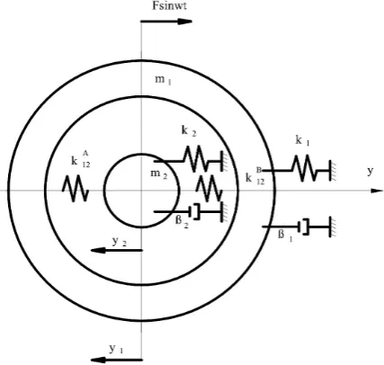
The designed model of double parting-off tool chambering which takes into account the influence of
basic groups, machining process and external forces of the system is shown on Fig. 1. The model pres-ents two point masses m1 and m2 with stationary base mounted by means of springs and absorbers with linear characteristics and rigidity and absorbency ratios respectively (k1 and k2, b1 and b2). Interreactions of masses in machining process are described by the linear characteristic with rigidity ratio
k
12A on thefirst parting-off tool and
k
12B on the second (located opposite the first tool).Fig. 1. Mechanical two-mass model of the OUPN system while chambering
Bonding ratio (machining rigidity) was defined analytically [1, 7, 2]. Machining process is described
by means of a spring with rigidity ratio k12 = kb, where k= s0x0 – the relative machining force (with ref-erence to the machined surface), x – chip shrinkage, b – the width of the machined layer. The width of the machined layer is the function of machining depth b = ap/tgKr, where Kr – the main approach angle.
k12 goes from maximum to minimum during a half-turn in the first parting-off tool and from min to max
in the second tool. The dynamic component of machining forces at the opposite parting-off tools, con-ditioned by the changing surplus brought about in the turning phase of the semi-manufactured product, are in the opposite phases.
, (1) where: w – angular part of the surplus change equal to the frequency of the part's revolution,
p – delay phase of machining force at the opposite parting-off tools,
у – surplus eccentricity.
of quadratic heterogeneous differential equations with constant coefficients.
(2) where:
y
y
x
A1 2
1
−
=
, y2−y1=x2B – relative displacement of a part and a tool on a parting-off tool A and B(a change in the thickness of the machined layer);
F(t); F1(t); F2(t) – periodic forces operating as a result of imbalance of revolving parts trans-ferred by the base and the component variables of the machining force.
After the relative displacement of the semi-manufactured product and the tool, machining depth changes equally on both parting-off tools in accordance with the largeness and the opposite, in accor-dance with the range of
(
xA xB)
2
1 =− . From the point of view of physics, double parting-off tool
machin-ing is characterized with a double displacement resistance x1,2. Delays in the change of machining force at a relative displacement of a part and tool can be disregarded due to the low time constant of the elastic system (t = 0,003 s) in comparison with the semi-manufactured product’s revolution time (t = 0,1 s) conditioning the change of the removed surplus. The expression 2k12(y1 – y2) may be considered as the quasistatic characteristic of machining process. Force F(t) which changes in a sinusoid manner was as-sumed as the fundamental external interference.
In case of a tool with guide bars, rigidity and absorbency ratios of the tool-support sub-system (PNS)
are defined by a connection reaction of linking bars with the surface of the machined hole k3 and b3. After simplifying the equation it assumes the following form:
(3) The technological system was examined analytically.
ANALYTICAL STUDY OF THE TECHNOLOGICAL SYSTEM OF DEEP HOLES CHAMBERING
An analytical study of the technological system in machining process was carried out in order to justify the minimization of relative vibrations’ amplitude as a result of automatic control of OUPN pa-rameters.
The following variables were introduced:
y
y
x
1=
1−
2;x
2=
y
1+
y
2;y
1=
1
2
(
x
1+
x
2)
;y
2=
1
2
(
x
2−
x
1)
.
(4) Right and left parts of equations were divided respectively by m1 and m2(
)
( )(
2
)
( )(
2
)
( )
2
sin
,
2
1
&x
&1+
&x
&2+
β
1m
1x
&1+
x
&2+
k
1m
1x
1+
x
2+
k
12m
1x
1=
F
0ω
t
(
)
( )(
2
)
( )(
2
)
( )
2
0
.
2
1
&x
&2−
&x
&1+
β
2m
2x
&2−
x
&1+
k
2m
2x
2−
x
1−
k
12m
2x
2=
(5)Both first and second equation were solved. Constant coefficients were grouped as regards new vari -ables, new designations were introduced::
+
=
2 2
1 1 1
2
1
m
m
r
b
b
;
−
=
2 2
1 1 2
2
1
m
m
r
b
b
,
+
=
2 2
1 1 1
1
2
m
k
m
k
c
;
−
=
2 2
1 1 2
2
1
m
k
m
k
c
, (6)
2 12
1 12 3
k
m
m
k
c
=
+
; 2
12
1 12 4
k
m
m
k
c
=
−
; 1
0
m
F
P
=
The following solution was obtained
e z
x = −iwt
1
1 ; x2= z2e−iwt, where: z1(w) = z0 eiKr= z
0 cosKr+ z0 sinKrj,
j – linearized rigidity coefficient.
Substituting the solution obtained in (6) and differentiating it with x1 and reducing it by e–iwt the
fol-lowing was obtained:
(
−
w
2−
r
1w
j
+
c
1+
c
3)
x
1+
(
c
2−
r
2w
j
)
x
2=
P
,
(
−
r
2w
02i
+
c
2+
c
4)
x
1+
(
c
1−
w
2−
r
1w
j
)
x
2=
P
.
(7)System determinant
.
...
....
2 2 1 4 2 2 2 2 2 3 1 1 2i
r
c
c
c
i
r
j
r
c
c
c
j
r
o
w
w
w
w
w
w
−
−
+
+
−
−
+
+
−
−
=
∆
(8)where: z ≤ c;
∆
=
w
4+
(
2
c
1−
c
3)
w
3+
c
12−
c
22+
c
1c
3−
c
2c
4.In accordance with Cramer’s systems,
=
∆
∆
=
11
x
X
(9)(
)
(
)
(
r
r
c
c
)
c
c
c
c
c
c
(
r
r
c
c
r
c
r
c
r
)
j
j
c
c
P
ω
ω
ω
ω
ω
ω
ω
ω
ω
2 1 1 2 2 2 1 1 3 1 4 2 3 1 2 2 4 1 1 3 2 1 2 2 4 2 2 2 12
2
2
2
Pr
Pr
1+
−
+
−
+
+
+
−
+
−
−
−
+
−
+
−
−
=
(9) can be presented as
, (10)
where: 2
2 2
w
−
=
m
k
P
A
; B = Pdw;C
=
r
1−
r
2, ;2 1 2 1
2
1
2
m
m
m
d
=
−
.The solution in the form of z1 = z0 cos(wt – Krj) is sought, where 2 22 22
0
C
A
D
B
z
+
+
=
.Expressing z0 by constant coefficients the following was obtained:
(
)
(
)
[
]
(
)
{
}
22 12 1 2 1 4 2 12 2 1 1 12 2 1 2 2 12 2 1 2 2 2 2 2 2 0 2 1
2
ω
λ
ω
ω
λ
ω
ω
ω
ω
λ
λ
λ
ω
λ
ω
ω
λ
d g k d r fk m k d m ek d P P z x + + + + + − + + + − + − = =The following designations were introduced
N
m
ek
=
+
−
2 12 2 1ω
λ
,
M fk m kd
λ
+λ
ω
− 12ω
2+ω
4 = 2 1 1 12 2 1,
L
g
k
d
r
1ω
2+
λ
1ω
+
12ω
=
2
.
Then
(
)
(
) (
)
[
]
22 2
2 2 2 2 2 2
1
l
l
w
w
w
l
d
L
M
N
d
P
P
x
+
+
+
+
−
=
(12) In order to evaluate the solution, equation (12) is differentiated by l2 and the numerator is equaled with zero. Roots of the equation l1 and l2 are
de-fined for (M / N + w2 = 0) then: l
2 – w2 = 0; l1 + M
/ N= 0; hence l2 = w2; l
1 = – M / N.
Substituting the obtained roots to (9) the fol-lowing was obtained
0 20
1 = − =
M M
P x
ω
;
(
ND
)
N
M
P
x
2
2
ω
+
=
.
(13)As a consequence, it was indicated that the relative vibrations amplitude x is a polynomial function of M, N, D, which include both
coef-ficients characterizing system’s parameters and
machining process.
When OUPN and machining parameters are selected in a particular manner, it can lead to a resonance.
The examination of solutions of the system
enables the determination of the influence of ab -sorbency on the relative vibrations amplitude. In order to carry out a numeric analysis of solutions
the following coefficients must be determined ei -ther experimentally or theoretically: m12, k, b, k12, F0. Reduced masses of the tool and parts are de-termined in accordance with the following:
2
f
k
m
=
. (14)The value of the reduced mass coefficient
max 0
A
F
K
=
b
p
, (15)where: Amax – resonance amplitude.
Absorbency coefficient is determined in ac -cordance with the width of resonance peak
(
)
f
f
f
1−
2= p
b
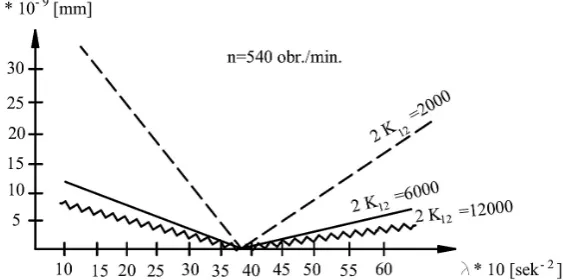
. (16)Fig. 2 presents the numerical solution of the system of equations. The analysis of the numeri-cal solution indicated that the regulation of rela-tive vibrations amplitude allows for the optimal control of rigidity.
Introduction of absorbency induces a phase shift of the tool and the part. Decreasing ampli-tude of relative vibrations along with the increase of machining rigidity enables the improvement
of precision and efficiency. The lowest amplitude
of relative vibrations can only be obtained when own frequency of tool-support sub-system equals the frequency of exciting force. The reduced fre-quency of tool-support sub-system cannot equal the external interference frequency at the set pa-rameters of OUPN system when rigidity at high yield parameter decreases, which facilitates the reduction of own frequency.
SUMMARY
While selecting rigidity and absorbency of tool-support sub-system one can control the fre-quency when the minimum of relative vibrations’ amplitude is obtained in radial direction.
As a result of OUPN parameters optimiza-tion, the transition processes time can be reduced, dynamic rigidity increased and the level of vi-brations reduced. When chambering thin-walled holes in sleeves, the rigidity of both part-support and tool-support sub-systems ought to be con-trolled in order to minimize the amplitude of rela-tive vibrations.
REFERENCES
1. Draczew O., Hałas W., Taranenko G., Taranenko W.: Sterowanie obróbką wibracyjną wałów o małej sztywności. Pomiary. Automatyka. Robotyka, no 2, 2008.
2. Fu H., Zhang L.: The model and experimental study for vibration control in deep-hole boring. 2011 2nd
International Conference on Mechanic Automation and Control Engineering, MACE 2011-Proced-ings, art. no. 5988464, pp. 6239-6242.
3. Szot T., Świć A.: Badania teoretyczne roztaczania otworów głębokich. W monografii Zastosowania informatyki w inżynierii produkcji. Lubelskie
Wydawnictwo Naukowe, Lublin 2009, pp. 93-104.
4. Szot T., Świć A.: Kształtowanie otworów głębokich narzędziem o zmiennej sztywności. Modele inżynierii teleinformatyki. Wybrane zagadnienia 3.
Koszalin 2009, pp. 50-57.
5. Świć A.: Technologia obróbki otworów o małej sztywności. Wydawnictwo Politechniki Lubel-skiej, Lublin 2007.
6. Świć A, Taranenko W, Szabelski J.: Modelling dy -namic systems of low-rigid shaft grinding.
Eksplo-atacja i Niezawodność – Maintenance and Reliabi -lity, 2(50), 2011, pp. 13-24.