1
EFFECT OF SEMI-CIRCLE RIB ON HEAT TRANSFER COEFFICIENT
IN A RECTANGULAR CHANNEL
Riyadh S. Al-Turaihi
a, Doaa Fadhil
a,b*, Azher M. Abed
ba Department of Mechanical Engineering, University of Babylon, Iraq
b Air conditioning and Refrigeration Techniques Engineering Department, Al-Mustaqbal University College, Babylon, 51001, Iraq
A
BSTRACTIn this paper an experimental and numerical analysis has been conducted to study the effect of heat transfer and filed flow of two-phase flow (water and air) through a rectangular ribbed channel. The study has involved the several values of heat flux (120,140,160 Watts), air and water superficial velocity (1.096, 1.425, 1.644, 1.864, and 2.193 m/s) and (0.0421, 0.0842, and 0.1474 m/s), respectively. The distribution of temperature along the channel was photographed using thermal camera and compared with numerical results . The experimental test system was fabricated of vertical rectangular channel with cross section of (0.08m × 0.03m) and a length (0.7 m) to analyze the behavior of the mixture (water-air) over the heated plate (semi-circle ribs ). The computational fluid dynamics CFD software was utilized to simulate the governing equations with initial and boundary conditions. Results found that the ribbed channel give the high heat transfer rate compared to the smooth channel. The percentage deviation between the experimental and numerical data is (1.0% - 6.0% ). The results proved that the flow is growing to become turbulent, eddies develop about the heated plate (rib), the temperature at the outlet decreases and heat transfer coefficient improved by adding ribs, it also improved when the velocities of the flow increased.
Keywords: CFD; Heated plate; Rectangular channel; Two-phase flow ; Turbulent flow
* Corresponding author. Email:
Doaa [email protected]
1.
INTRODUCTION
The two-phase flow (water-air) used in a wide range of application such as air conditioning, fields of energy, petroleum, refrigeration, nuclear – power generation, mechanical industries, and heating systems, due to its attractive characteristics such as high heat and mass transfer rates between phases, temperature homogeneity, and good mixing of phases.
Ribbed channels are generally utilized for the improvement of convection heat transfer. The presence of ribs in the channels generated a turbulence flow and the thermal boundary layer thickness are reduced by separating the laminar sub-layer if compared with the smooth channel, and this drives to an increase in the heat transfer rate. This work can be accomplished by maintaining the height of the roughness parts small compared with the dimensions of the (Manca et al., 2011; Abed et al., 2015; Abed et al., 2015). Understanding the conduct of the mixture in rectangular channel with rib is requiring due to the common apparition of this phenomenon in a thermal engineering systems. Many researchers have used computational fluid dynamics (CFD) to prophesy the hydrodynamics of the two-phase flow employing two approaches Eulerian Lagrange and Eulerian- Eulerian because the complexity of the two-phases movement and the interface amidst them is unknown and transient (Kumar and Natarajan 2009). Pinelli and Magelli (2000) studied the behavior of the mixture of liquid and gas in high side rate reactors stirred with multiple hydrofoil impellers pumping downward. Yang et al., (2000) used CFX approach (Lattice-Boltzmann) method to study and simulate the hydrodynamics of Taylor bubbles in a tight duct. Qu and Mudawar (2003) studied heat transfer for flow boiling in a water-cooled Microchannel heat sink. Koşar
(2008) studied experimentally and numerically the pressure drop and pattern for the flow of (water-air, and R-123 boiling) inside a hydrofoil based micro pin blade heat sink. Ansari and Arzandi (2012) studied adiabatic two-phase flow (water - air) in downy and ribbed rectangular duct at approximately the atmospherically situations. Three ribs have several rises where they were placed at three various positions in the duct to get three situations. Al-Turaihi (2016) performed experimental and simulation study of a pressure difference for two-phase flow (air-water) about upright hydrofoil for several attack angles through a rectangular expanding duct. Lim et al., (2013) examined experimentally the pressure drop of single-phase and two-phase under the adiabatic and heat transfer condition inside round glass pipes. Mohebbi et al., (2015) investigated numerically the characteristics of forced convection heat transfer for Al2O3-water nanofluid at different Reynolds numbers and nanoparticles volume fractions, flowing inside a ribbed tube with different rib shapes and at different geometric ratios (t/p) of ribs. Constant wall heat flux condition was applied and resulted in constant heat rate of Q=10,000 Watts for all simulations. Kong and Kim (2017) studied experimentally the characteristics of two-phase flow in a circular pipe. Al—Jibory et al., (2018) studies the effect of entrance velocity of two-phase flow (air-water), and the position of grooves on the heat transfer coefficient and the distribution of temperature over the test channel. Bhattacharyya et al., (2018) experimentally and numerically investigated the characteristics of convection heat transfer in a circular pipe supplied with twisted tape with Re ranging from (100 to 2000), the entrance angle of pipe (140º to 180º), and the twisted ratio (18 to 30). Kim et al., (2016) performed numerical investigation to determine the effects of entrance velocity of coolant flow on the characteristics of flow and convection heat transfer
2
in a ribbed duct. Eiamsa-Ard and Promvonge (2009) studied the effects of rib-grooved compound tabulator on the forced heat transfer coefficient within a rectangular ribbed duct under a regular heat flux condition. Manca et al., (2010) performed a numerical studied on air forced convection inside a rectangular duct fitted with ribs with a fixed heat flux applied on the bottom and upper external walls. Boulemtafes-Boukadoum and Benzaoui (2014) investigated numerically the heat transfer characteristics by adopting CFD approach through a solar air heater fitted with semi-circle sectioned transverse rib roughness. Fifi et al., (2012) conducted an numerical analysis to study the forced convection heat transfer in a rectangular duct fitted with two shape of ribs (square and trapezoidal) on the bottom wall using different coolant fluids like (air, vapor, air/mist, and vapor/mist). Selvaraj et al., (2013) theoretically formed a model to simulate flow of water with convection heat transfer through a smooth tube and tube fitted with the three shapes of grooves (circular, square and trapezoidal) using CFD approach. O
OlleeiiwwiiaannddAAll--TTuurraaiihhii((22001199)) experimentally and numerically studied the heat transfer characteristics and filed flow in vertical duct ribbed with rectangular ribs . Three ratio of Rib height to the duct width (0.083, 0.167, and 0.25) was studied .It was found that the heat transfer rate increased as the e/w ratio increased. Salman (2019) presented a numerical investigation of turbulent flow (nanofluids) to study the effects of shapes of ribs on heat transfer and thermal performance coefficients. Hong et al., (2019) investigated experimentally thermal-hydraulic behaviors of air turbulent flow in a traverse corrugated tube inserted with twin and triple wire coils.
In the present study, the experimental data has been matched with a result achieved by ANSYS Fluent 15.0 and observed a good contract. The main objective of this investigation is to study experimentally and numerically the influence of using several values of the superficial velocity of (water and air) and adding of rib inside the channel on the temperature distribution and the forced local heat transfer coefficient. Also, compare the experimental and numerical results of the ribbed channel (semi-circular rib) with a smooth channel for a turbulent flow inside a vertical rectangular channel subjected to a constant heat flux.
2.
MATHEMATICAL AND COMPUTIONAL
MODAL
2.1
Experimental Test
The test channel was structured to study the effect of the two-phase flow (water –air) over semi-circle ribs on heat transfer coefficient in vertical rectangular channel. Figure (1) illustrates the devices utilized for the experimental test and measuring system. Perspex transparent channel used with a rectangular cross section (0.08m × 0.03m) and a length (0.7 m) to report the demeanor of the mixture (water – air) over the heated plate (rib). Five taps along the side test channel were utilized for temperature sensors that used to measure the temperature along the channel. The semi – circle rib placed in the test section, as shown in Fig. 2. The water pumped with maximum discharge of (0.00834 m3/s) from the water tank and forced to the test channel. In order to control the amount of water flowing a valve is used of (1 inch) diameter. Flow meter that has ranges from (0 - 0.0005 m3/s) was utilized to measure the amount of water flow rate. The air compressor with a specification capacity (0.5 m3) and maximum pressure (16 bars) used to provide gas phase (air) into the test section. Flow meter that has ranges from (0.0000972 m3/s to 0.000972 m3/s) was utilized to measure and control the amount of air flow rate. The electrical voltage provided into the heaters by a power supply with a maximum voltage (260 V), with Digital Power Analyzers was utilized to balance the electrical voltage across the heaters. Two Heaters were placed at the outer surface of the heated plate. A Sony digital video camera (DCR-SR68E model) was utilized to record the flow behavior through the test channel. A thermal camera with a high accuracy of ±2°C or ±2%, with dimensions/weight 8.8 × 3.1 × 3.4" (223×79×85mm) /< 12.9oz. (365g), was utilized to
record the distribution of temperature for the mixture of (water-air) inside the channel. The experimental procedures are as follows:
1. The water enters the duct with the first value of the flow rate from Table 1.
2. Heat the target region (ribbed plate) by supplying an electrical power to heaters.
3. The desired temperature is established.
4. The air enters the duct with the first value of the flow rate from Table 1.
5. Closing the air and water valves respectively.
6. Repeating the above steps for each value of water and air flow rates.
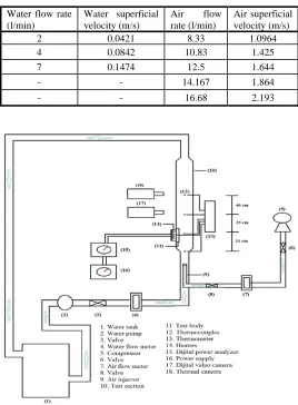
Several values of water and air flow rates were utilized in order to measure the temperature in various working conditions, as illustrate in Table 1. Series of valves and by-passages were utilized to control the flow rates of water and air before being measured by flow meters. The water and air phases were blended in a mixing device before they entered the channel.
Table 1 Working Conditions Values.
Fig. 1 Schematic diagram of the present work
Fig. 2 Semi-Circle Rib Water flow rate (l/min)
Water superficial velocity (m/s)
Air flow rate (l/min)
Air superficial velocity (m/s)
2 0.0421 8.33 1.0964
4 0.0842 10.83 1.425
7 0.1474 12.5 1.644
- - 14.167 1.864
3
2.2
Numerical Analyzing
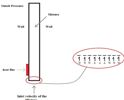
For each experiment of the test, a numerical analysis was achieved utilizing Ansys Fluent (version15.0). The model was considered a two-dimensional rectangular geometry structure modeled with Ansys Workbench 15.0, with the same dimensions as the experimental rig, width of 3 cm with a height of 70 cm. The lower edge of the test channel is divided into nine pieces to represent the entrance of water and air into the pipe as shown in Fig. 3. Quad/tri mesh was employed to produce 2281 element and 2531 node.
Fig. 3. Two-phase Problem Description.
The Continuity, momentum and energy of two-dimensional steady state forced convection flow equations are:
The Continuity equation is:
( )
m .(
m m)
0t ρ ρ υ
∂ + ∇ =
∂
(1) The mass-averaged velocity υm is represented as:
1
n
k k k k m m
α ρ υ
υ
=∑
=ρ
(2) and ρm is the density of mixture :1
n
m k k
k
ρ
α
ρ
=
=
∑
(3) αk is the volume fraction of phase k.
The Momentum equation is:
(
)
(
)
(
)
, ,
1
. .
.
m m m m m m m m n
k
m k dr k dr k k t g F
ρ
υ
ρ
υ υ
µ
υ
υ
ρ
α
ρ
υ υ
Τ = ∂ + ∇ = − ∇Ρ + ∇ ∇ + ∇ + ∂ + + ∇ ∑ (4) Where n is the number of phases , F is a body force, and μm is the viscosity of the mixture, which is given by:1 n k m k k
µ
α
µ
= =∑
(5) Where υdr,k is the drift velocity for secondary phase k:The energy equation is :
(
)
(
(
)
)
(
1)
1.
. k
n n
k k
k k k k k
k k eff t S ρ ρ α α υ = = Ε ∂ + = ∂ ∇ + ∇ + Ρ Ε Ε ∇Τ
∑
∑
(6)Where Keff is the effective conductivity, Kt where is the turbulent thermal conductivity. The first term on the right-hand side of Eq. (6) represents energy transfer due to conduction. SE includes any other volumetric heat sources.
2.3
Turbulence Model
Ansys Fluent 15.0 displays three methods for k-ɛ turbulence model in the two-phase flow which are:
1. .Turbulence mixture model 2. .Turbulence dispersed model 3. .Turbulence model for each phase
Depending on the deviation between experimental and numerical results, being choosing the turbulence k-ɛ standard mixture model was set for the two phases model which can be defined through these equations (Fluent 2006, Habeeb and Al-Turaihi 2013)
( )
(
)
,,
. . t m
k m
m m m m
k
t k k k G ε
µ ρ ρ υ σ ρ ∂ +∇ =∇ ∇ + − ∂
(7)(
)
(
)
,(
)
1 , 2
. . t m
k m
m m m m
t k C Gε C ε
ε µ ε ε ε ε ε ρ ρ υ ρ σ ∂ + ∇ =∇ ∇ + − ∂ (8)
Where ɛ is the turbulent dissipation rate, Gk is the generation of turbulence kinetic energy, and σ is the turbulent Prandtl number for κ and ɛ .
The turbulent viscosity, μt,m , and the production of turbulence kinetic energy, Gk,m, are computed as following:
2 ,
t m m
k C µ
µ
=ρ
ε
(9)
(
)
,m t m, m m : m
Gκ µ υ υ υ
Τ
= ∇
+∇
∇
(10) The model constants can be seen in Table 2.
Table 2 Model Constants.
Based on the basic two-phase turbulent flow experiments, these default values were determined. Equations (1)-(10) are solved using non-dimensional initial boundary conditions:
Inlet Velocity
The lower edge of the channel represents the entrance to the channel. The superficial velocities of water and air are used as the inlet boundary condition, which is set as:
( )
( )
0 , inlet velocity , 287
0 , 0
U U U U in x y x y x x K = = = ∂ = ∂ = ∂ ∂ Τ
Wall
Left side wall of the smooth and ribbed rectangular channel at semi - circle rib was exposed to a constant heat flux. While the remaining portion of the channel wall was set to be adiabatic.
Outlet
The upper edge of the channel was set as outlet pressure. The internal zones that shared common faces did not require any In order to prove the validity and accuracy for the turbulence model and numerical procedure for this work, previous work for (Jalghaf et al., 2016) has been performed. Ansys Fluent 15.0 is used to calculate numerically the exist temperature for the mixture around a two-dimensional heated body (Circular-Cylinder) in a horizontal rectangular channel of dimensions (8×3×70 cm). The numerical temperature that was found was compared with the experimental temperature from the work of the other researchers. The validation trials were performed for 12 tests which consisted of (heated body, three air discharge (0.0972, 0.139, and 0.278 m/s), two water discharge (0.0334, and 0.167 m/s), and one heat flux (506 Watts).
The constant Value
σk 1.00
σɛ 1.30
C1ɛ 1.44
C2ɛ 1.92
4
Fig. 4 Comparison between the Experimental and the Numerical Values of exist Temperature for (Jalghaf et al., 2016).
3.
RESULTS AND DISCUSSIONS
The temperature distribution across the duct as well as the heat transfer coefficient was found experimentally and numerically.
The effect of water superficial velocity is presented as pictures and temperature - length graphs. The temperature was measured at five points along the test channel. The experimental heat transfer coefficient was computed utilizing Eq. (11)
h= q/∆T (11) The temperature difference that used in this equation is (Ts-Tb), Ts is the temperature of the heat plate which is measured by thermocouples. The bulk temperature (Tb) at location Y along the streamwise direction, and It was calculated assuming a linear working fluid temperature rise along the rectangular channel and is defined as (Islam et al., 1998; Ghorbani-Tari 2014)
Tb = Ts + (Tout-Tin) Y/L (12) Where Ts, Tin and Tout were read from thermocouple output.
3.1 EFFECT OF SUPERFICIAL VELOCITY
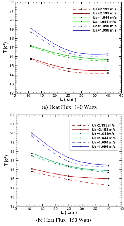
Fig. 5(a) and (b) offers the effect of air superficial velocity on the temperature profile for different values of heat flux, with respect to the length taken from the air injection. When air superficial velocity increased, the temperature decreased, due to the reduction in the time residence of the mixture and increase the amount of air inside the channel, and adding of ribs provide a surface area for heat transfer and interrupt the development of the boundary layer and create turbulent flow inside the channel. These figures display a comparison amidst the experimental and the numerical data, were solid and dotted lines represented the experimental and numerical data, respectively. The numerical data were taken at the same point where the temperature sensor existing experimentally.
As the air superficial velocity increased from (1.0964 m/s to 2.193 m/s) at constant water superficial velocity and heat flux (0.0421 m/s and 140 Watts), respectively, the value of temperature difference decrease from (19.2 ºC to 15.8 ºC). There is a deviation amidst the experimental and the numerical data about (1 – 8 %) because the flow enters into the test channel in a different way from that in the actual test.
The temperature difference behavior, it can be noted that, the temperature difference decreased as the air superficial velocity increased according to the relation:
q=m cp• ∆Τ (13)
Where
m•=
ρυ
Α (14)From Eq. (13), it can be noted that, the temperature difference inversely proportional with the air superficial velocity.
As the heat flux increased from (140 Watts to 160 Watts), and air superficial velocity increased from (1.0964 m/s to 2.193 m/s), respectively, the value of temperature difference increased.
(a) Heat Flux=140 Watts
(b) Heat Flux=160 Watts
Fig. 5 Effect of air superficial velocity on temperature profile at constant water superficial velocity (0.0421 m/s) for different values of heat flux : a) 140 Watts, and b) 160 Watts.
3.2
EFFECT OF HEAT FLUX
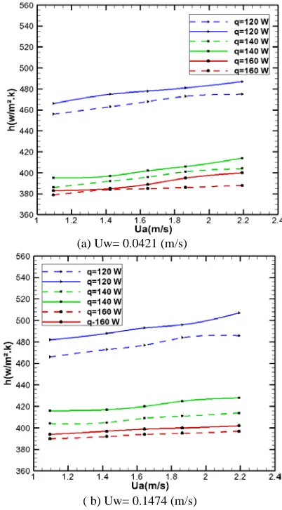
Fig. 6 (a)&(b) shows the effect of heat flux on the local heat transfer coefficient profile, with respect to the air superficial velocity. When air superficial velocity increased the local heat transfer coefficient increased for several values of heat flux. This is due to the high velocity of air which led to more disturbances in the flow along with the existence of the rib and provided higher turbulent flow. A periodic redevelopment of the boundary layers over their rib caused a more effective heat transfer, also, the existence of the rib increased heat transfer area. Fig. 6 (a)&(b) also displays a comparison amidst the experimental and the numerical data as the influence of water superficial velocity increased on the local heat transfer coefficient profile at different values of the heat flux, where solid and dotted lines represented the experimental and numerical results, respectively. Fig. (6-a), as the air superficial velocity increased from (1.0964 m/s to 2.193 m/s) at constant water superficial velocity and heat flux (0.0421 m/s and 120 Watts), respectively, the value of experimental and numerical heat transfer coefficient increase from (466.2 W/m2 .K to 487.1 W/m2 .K), and from (456.4 W/m2 .K to 476.4 W/m2 .K), respectively.
5 water inside the channel, and adding of ribs provide a surface area for heat transfer and interrupt the development of the boundary layer and create turbulent flow inside the channel.
From fig. 6 (a)&(b), as the air superficial velocity increased from (1.0964 m/s to 2.193 m/s) and water superficial velocity increased from (0.0421 m/s to 0.1474 m/s), at constant heat flux (120 Watts), respectively, the value of experimental and numerical heat transfer coefficient increase from (466.2 W/m2 .K to 509.9 W/m2 .K), and from (456.4 W/m2 .K to 490.0 W/m2 .K), respectively.
From Eq. (11) and Eq. (13), it can be observed that, the heat transfer coefficient directly proportional with the water superficial velocity and inversely proportional with the temperature difference, since the heat transfer coefficient as show previously increased as the water superficial velocity increased and temperature difference decreased. The influence of air superficial velocity on the heat transfer coefficient results was the same effect of water superficial velocity on it, but with less percentage, about (2.4%) for channel fitted with semi-circle rib, because water is the primary phase and have a thermal conductivity higher than from the air.
(a) Uw= 0.0421 (m/s)
( b) Uw= 0.1474 (m/s)
Fig. 6 Effect of heat flux on heat transfer coefficient at water superficial velocity: a) Uw= 0.0421 (m/s), and b)Uw= (0.1474 m/s)
3.3
Effect of Semi-Circle Rib
After understanding the flow phenomena through a ribbed channel and its influence on both temperature distribution and heat transfer, it must be compared with that of a similar smooth channel. Fig. 7 offers the heat transfer coefficient for both smooth and ribbed channel at different superficial velocities of air and constant water superficial velocity (0.1474 m/s), and constant heat flux (120 Watts). It can be shown that the heat transfer coefficient for channel fitted with semi-circle rib shape
was greater that smooth channel by 59%. Attributing the cause of this effect to the presence of the ribs inside the channels, where these ribs provide additional surface area for heat transfer and create a turbulence flow by breaking the laminar-sub layer, and as a result of this effect, the heat transfer coefficient increase because of both increased surface area and increased turbulence.
Thus the channel fitted with semi-circle rib had a higher rate of heat transfer of the smooth rib, because it had a sharpened edge and smallest tip, so the area for the leading edge and the trailing edge behavior was at its biggest value for the smooth rib and at its smallest value for the semi-circle rib and this produces additional area for heat transfer and generated a turbulence flow higher than the smooth rib. The activity of the ribbed channel improved as the water superficial velocity increased which produced an increase in the turbulent of the flow and the recirculation as well to cause a decrease in the temperature distribution inside the channel, this means an increase in the rate of heat transfer. The flow at the leading edge of the rib had high velocity whereas at the rib the flow was separated and reattached after the trailing edge.
Fig. 7 Comparison the local heat transfer coefficient of smooth and ribbed channel at water superficial velocity (0.1474 m/s) and heat flux (120 Watts).
The flow within the channel becomes more turbulence when the superficial velocity of water and air increases as presented in Figs. (8-a) to (8-b). These figures illustrate the behavior of experimental two-phase flow utilizing the photos taken to flow within the channel and visually comparing them with the contour of water volume fraction obtained by numerical analysis. when air flow rate increased, the flow became unstable and unsymmetrical over the heated plate with an increase in the size and number of bubbles .This is due to the high velocity of water and air led to a more disturbance in the flow.
Fig. (8-a), shows the images taken for the duct, the images focus on the ribs region of the duct which means it doesn’t show the entire duct. Fig. (8-b), shows the images taken for the numerically simulated duct, the images show the entire duct which one of the privileges of using the computational fluids dynamics such as Ansys Fluent. From the previous figures, there is a good similarity between experimental and numerical images, the simple difference between them is due to the difference in time taken. All the numerical images were taken at the same time (2.5 second), meanwhile, the experiment images were taken at different times ranging from (1 to 5 second).
6
distribution with the raise in the heat flux or flow rate. The images of Fig. (9a), shows the distribution of temperature just in the ribs region, as the thermal camera was focused on this region. The images of Fig. (9b), shows the distribution of temperature in the entire duct as the flow of water and air passes over the heated rib.
a. Experimental b. Numerical
Fig. 8 The Contours of water volume fraction at 0.0421 m/s water superficial velocity and heat flux 120 W for Semi-Circle Rib
Fig. 9 offers the contours of temperature distribution through a channel supplied with semi-circle rib at several values of air superficial velocity and constant heat flux. The temperature distribution over the rib wall decreased as the air superficial velocity increased due to the increase in the amount of air and reduce the time residence of the flow inside the channel according to Eq. (13).
a. Experimental b. Numerical
Fig. 9 Contours of static temperature at q = (120 watt), Uw = (0.0421 m/s), and Ua = (1.0964, 1.425, 1.6446, 1.864, 2.193 m/s), respectively.
4.
CONCLUSIONS
This work described an experimental and theoretical study of temperature, local heat transfer coefficient, and the behavior of two-phase flow through a rectangular ribbed channel. Stainless steel semi – circle rib was used as a heated plate. Temperature was measured at five locations along the test section. The temperature was measured at five positions along the test channel. The behavior of two-phase flow was photographed utilizing a Sony digital video camera and thermal camera. Concluding comments are abstracted below.
1. While the air and water superficial velocities raise, the flow grows, eddies develop nearby the surface of the rib.
2. While the air and water superficial velocities raise, the local heat transfer coefficient increments due to the existence of the rib which leads to raising the area of heat transfer.
3. Increasing the superficial velocity of water and air from (0.0421 to 0.1474 m/s) and from (1.0964 to 2.193 m/s), respectively, lead to improving the experimental and numerical heat transfer coefficient by (11.5%, 10.9%) for the channel fitted with semi-circle rib, respectively. This occurs at constant heat flux (120 Watts).
4. Increasing the superficial velocity of water and air from (0.0421 to 0.1474 m/s) and from (1.0964 to 2.193 m/s), respectively, lead to increase the experimental and numerical results of heat transfer coefficient through ribbed channel was greater than a smooth channel by (59% and 57% for channel fitted with semi-circle rib). This occurs at constant heat flux (120 Watts).
5. Temperature distribution has an inverse proportional with the superficial velocity of water and air along the channel for the turbulent two-phase flow, were increasing these variables leads to a decrease in the temperature difference along the channel.
NOMENCLATURE
A cross-sectional area (m2 )
D channel hydraulic diameter (m)
E energy (J)
G acceleration of gravity; Standard values = 9.80665 ( m/s2)
h local heat transfer coefficient (W/m2.K)
I turbulent intensity
k thermal conductivity (W/m .K)
m• mass flow rate (Kg/s)
p pressure (N/m2)
q heat flux (Watts)
Q volume flow rate (m3/s)
Re Reynolds number
t time (sec)
T temperature (Cº)
U superficial velocity (m/s)
ʋ mass averaged velocity (m/s)
w wetted perimeter of the channel (m)
Greek Symbols
∆P pressure drop (Pa)
∆T temperature difference (Cº)
µ dynamic viscosity (kg/m. s)
ɛ turbulent dissipation rate (m2/s3)
α volume fraction
ρ mass density (kg/m3)
к turbulent kinetic energy (m2/s2)
Tin inlet temperature (Cº)
Tout outlet temperature (Cº)
Ts surface Rib temperature (Cº)
Tb bulk temperature of the mixture (Cº)
Q volume flow rate (m3/s)
Y position heat transfer coefficient in y-direction (m) L heated surface length (m)
REFERENCES
Abed, A. M., M. Alghoul, K. Sopian, H. Mohammed and A. N. Al-Shamani (2015). "Design Characteristics of Corrugated Trapezoidal Plate Heat Exchangers Using Nanofluids." Chemical Engineering and Processing: Process Intensification 87: 88-103. https://dx.doi.org/10.1016/j.cep.2014.11.005
Abed, A. M., K. Sopian, H. Mohammed, M. Alghoul, M. H. Ruslan, S. Mat and A. N. Al-Shamani (2015). "Enhance Heat Transfer in the Channel with V-Shaped Wavy Lower Plate Using Liquid Nanofluids."
Case Studies in Thermal Engineering 5: 13-23. https://dx.doi.org/10.1016/j.csite.2014.11.001
7 Al—Jibory, M., R. Al—Turaihi and H. Al—Jibory (2018). "An Experimental and Numerical Study for Two Phase Flow (Water-Air) in Rectangular Ducts with Compound Turbulators." IOP Conference Series: Materials Science and Engineering, IOP Publishing. https://dx.doi.org/10.1088/1757-899X/433/1/012049
Ansari, M. and B. Arzandi (2012). "Two-Phase Gas–Liquid Flow Regimes for Smooth and Ribbed Rectangular Ducts." International Journal of Multiphase Flow 38(1): 118-125. https://dx.doi.org/10.1016/j.ijmultiphaseflow.2011.08.008
Bhattacharyya, S., H. Chattopadhyay and A. Haldar (2018). "Design of Twisted Tape Turbulator at Different Entrance Angle for Heat Transfer Enhancement in a Solar Heater." Beni-Suef University Journal of Basic and Applied Sciences 7(1): 118-126. https://dx.doi.org/10.1016/j.bjbas.2017.08.003
Boulemtafes-Boukadoum, A. and A. Benzaoui (2014). "CFD Based Analysis of Heat Transfer Enhancement in Solar Air Heater Provided with Transverse Rectangular Ribs." Energy Procedia 50: 761-772. https://dx.doi: 10.1016/j.egypro.2014.06.094
Eiamsa-Ard, S. and P. Promvonge (2009). "Thermal characteristics of turbulent rib-grooved channel flows." International Communications in Heat and Mass Transfer 36(7): 705-711. https://dx.doi.org/10.1016/j.icheatmasstransfer.2009.03.025
Fifi, N. E., M. A. Antar and Z. Qun (2012). "Numerical Investigation of Heat Transfer Coefficient in Ribbed Rectangular Duct with Various Shaped Ribs and Different Coolants." Proceedings of the 1st International Conference on Mechanical Engineering and Material Science, Atlantis Press.
https://dx.doi.org/10.2991/mems.2012.119
Fluent, I. (2006). "FLUENT 6.3 User’s Guide." Fluent Documentation.
Ghorbani-Tari, Z. (2014). "Experimental Investigations of Heat Transfer in a Channel with Ribs and Obstacle." Lund University. Habeeb, L. J. and R. S. Al-Turaihi (2013). "Experimental Study and CFD Simulation of Two-Phase Flow Around Triangular Obstacle in Enlarging Channel." Int. J. Eng. Res. Appl 3(4): 2036-2042.
Hong, Y., J. Du, S. Wang, W.-B. Ye and S.-M. Huang (2019). "Turbulent Thermal-Hydraulic and Thermodynamic Characteristics in a Traverse Corrugated Tube Fitted with Twin and Triple Wire Coils."
International Journal of Heat and Mass Transfer 130: 483-495. https://dx.doi.org/10.1016/j.ijheatmasstransfer.2018.10.087
Islam, M. S., R. Hino, K. Haga, M. Monde and Y. Sudo (1998). "Experimental Study on Heat Transfer Augmentation for High Heat Flux Removal in Rib-Roughened Narrow Channels." Journal of nuclear science and technology 35(9): 671-678. https://dx.doi.org/10.1080/18811248.1998.9733923
Jalghaf, H. K., R. S. Al-Turaihi and J. Habeeb (2016). "Air-Water Flow Investigation Around Hot Circular Cylinder Inside Channel." Advances in Natural and Applied Sciences10(12): 16-28.
Kim, D. H., B. J. Lee, J. S. Park, J. S. Kwak and J. T. Chung (2016). "Effects of Inlet Velocity Profile on Flow and Heat Transfer in the Entrance Region of a Ribbed Channel." International Journal of Heat and Mass Transfer 92: 838-849. https://dx.doi.org/10.1016/j.ijheatmasstransfer.2015.05.077
Kong, R. and S. Kim (2017). "Characterization of Horizontal Air– Water Two-Phase Flow." Nuclear Engineering and Design312: 266-276. https://dx.doi.org/10.1016/j.nucengdes.2016.06.016
Koşar, A. (2008). "Two-Phase Pressure Drop Across a Hydrofoil-Based Micro Pin Device Using R-123." Experimental Thermal and Fluid Science32(6): 1213-1221.
https://dx.doi.org/10.1016/j.expthermflusci.2008.02.005
Kumar, M. M. and E. Natarajan (2009). "CFD Simulation for Two-Phase Mixing in 2D Fluidized Bed." The International Journal of Advanced Manufacturing Technology: 1-4.
https:// doi.org/10.1007/s00170-008-1875-9
Lim, Y., S. Yu and N. Nguyen (2013). "Flow Visualization and Heat Transfer Characteristics of Gas–Liquid Two-Phase Flow in Microtube Under Constant Heat Flux at Wall." International Journal of Heat and Mass Transfer56(1-2): 350-359.
https://dx.doi.org/10.1016/j.ijheatmasstransfer.2012.08.063
Manca, O., S. Nardini and D. Ricci (2010). "Numerical Study of Air Forced Convection in a Rectangular Channel Provided with Ribs." 2010 14th International Heat Transfer Conference, American Society of Mechanical Engineers Digital Collection.
https://dx.doi.org/10.1115/IHTC14-23244
Manca, O., S. Nardini and D. Ricci (2011). "Numerical Study of Air Forced Convection in a Channel Provided with Inclined Ribs."
Frontiers in Heat and Mass Transfer (FHMT)2(1). http://dx.doi.org/10.5098/hmt.v2.1.3007
Mohebbi, K., R. Rafee and F. Talebi (2015). "Effects of Rib Shapes on Heat Transfer Characteristics of Turbulent Flow of Al2O3-Water Nanofluid Inside Ribbed Tubes." Iranian Journal of Chemistry and Chemical Engineering (IJCCE) 34(3): 61-77.
Oleiwi, S. and R. Al-Turaihi (2019). "The Effect of Ribs Height in Two Phase Flow (Air-Water) on Heat Transfer Coefficient in Vertical Ribbed Duct." Ain Shams Engineering Journal.
https://dx.doi.org/10.1016/j.asej.2019.01.002
Pinelli, D. and F. Magelli (2000). "Analysis of the Fluid Dynamic Behavior of the Liquid and Gas Phases in Reactors Stirred with Multiple Hydrofoil Impellers." Industrial & engineering chemistry research39(9): 3202-3211.
https://dx.doi.org/10.1021/ie000216+
Qu, W. and I. Mudawar (2003). "Flow Boiling Heat Transfer in Two-Phase Micro-Channel Heat Sinks––I. Experimental Investigation and Assessment of Correlation Methods." International journal of heat and mass transfer46(15): 2755-2771.
https://dx.doi.org/10.1016/S0017-9310(03)00041-3
Salman, S. D. (2019). "Comparative Study on Heat Transfer Enhancement of Nanofluids Flow in Ribs Tube Using CFD Simulation." Heat Transfer—Asian Research48(1): 148-163.
https://dx.doi.org/10.1002/htj.21376
Selvaraj, P., J. Sarangan and S. Suresh (2013). "Computational Fluid Dynamics Analysis on Heat Transfer and Friction Factor Characteristics of a Turbulent Flow for Internally Grooved Tubes."
Thermal Science17(4).
https://dx.doi.org/10.2298/TSCI110404010S
Yang, Z., B. Palm, I. Kazachkov and B. Sehgal (2000). "On Mechanism of Enhancement of Two-Phase Flow Heat Transfer in a Narrow Channel." ITHERM 2000. The Seventh Intersociety Conference on Thermal and Thermomechanical Phenomena in Electronic Systems (Cat. No. 00CH37069), IEEE.