Research Journal
Volume 10, No. 29, March 2016, pages 52–56
DOI: 10.12913/22998624/61931 Research Article
Received: 2015.12.15 Accepted: 2016.02.01 Published: 2016.03.01
OPTIMIZATION OF I-SECTION PROFILE DESIGN BY
THE FINITE ELEMENT METHOD
Patryk Różyło1
1 Faculty of Mechanical Engineering, Lublin University of Technology, Nadbystrzycka 36, 20-618 Lublin, Poland,
e-mail: [email protected]
ABSTRACT
This paper discusses the problem of design optimization for an I-section profile. The optimization process was performed using the Abaqus program. The numerical analy-sis of a strictly static problem was based on the finite element method. The scope of the analysis involved both determination of stresses and displacements in the profile and structure topology optimization. The main focus of the numerical analysis was put on reducing profile volume while maintaining the same load and similar stresses prior to and after optimization. The solution of the optimization problem is just an example of the potential of using this method in combination with the finite element method in the Abaqus environment. Nowadays numerical analysis is the most effec-tive cost-reducing alternaeffec-tive to experimental tests and it enables structure examina-tion by means of a computer.
Keywords: Abaqus, optimization, numerical analysis.
INTRODUCTION
The current trend in technological develop-ment is to reduce weight, dimensions and stresses of structural profiles. What is significant here is maintaining their basic properties such as rigidity, load-carrying capacity and general strength. An engineering approach is to reduce material vol-ume for individual structures while maintaining its basic mechanical and strength properties at the same time. A dominant trend which is more and more intensively developed is design optimiza-tion. The essence of optimization is to determine optimal and the most favourable design solution. In engineering terms, optimization is connected with re-designing a given structure so that this structure has smaller overall dimensions, vol-ume, weight or stresses, but it retains its initial material and strength properties. The technical development is aimed at producing parts which are cheaper, more durable and have improved de-sign. The optimization process comprises many factors; however, with the use of the finite ele -ment method this process is relatively easy and
requires minimum user’s knowledge depending on how a given object is to be optimized.
Topology optimization provides information concerning location of material for a structure in the workspace such that the structure’s geometry is the best possible (optimal) with the applied boundary conditions and load. The optimization process consists in determining a certain maxi-mum or minimaxi-mum of a function, while meeting specified conditions that limit a given problem. In topology optimization it is crucial that the region which is redundant in terms of excessive volume be effectively reduced by correctly defined loads and boundary conditions.
element method. They discussed the problem of optimization with respect to structure shape and common physical phenomena.
The problem discussed in this paper per-tains to a modern approach to structure analysis in topology optimization based on the use of the Abaqus program. Structural profiles which are widely used in building industry or as a part of industrial machines should be constantly modern-ized in order to obtain similar mechanical prop-erties at reduced weight or limited workspace. The process of design topology optimization is an innovative engineering approach which results in decreasing the structure’s initial volume in the regions which are not in operation or under load. The problem of profile optimization using the Abaqus system still requires a great deal of work and experience. An example of a real model just before and after optimization is shown in a figure below (Fig. 1).
Optimization is usually a one- or multi-crite-ria based process. With such numerical systems as Abaqus, the user can perform design optimiza-tion in several independent categories depending
on a set of given optimization process criteria. Optimization is applied wherever two or more given solutions are necessary and possible. This process is employed to obtain a product with op-timal properties depending on its desired use.
This paper presents the solution to a numeri-cal problem of design optimization for a steel I-section profile using the existing optimization methods. Additionally, the study is motivated by the need of developing computer-based numeri-cal analyses, the results of which highly agree with those of real analyses.
MATERIALS AND METHODS
The study was performed on a numerical model of a steel I-section profile prepared in the numerical environment Abaqus 6.14. The profile was assigned the material properties of steel com-monly denoted as ST3S (S235).
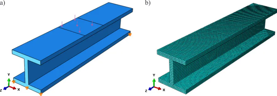
The numerically defined material had elastic properties with the Young modulus in fibre direc -tion set approximately to E=210000 MPa and Poisson’s ratio set to v=0.3. The plastic properties of the material were as follows: the yield point Re was 235 MPa, the tensile strength Rm was 360 MPa, while the ultimate elongation A was 24% for the profile wall thickness which did not ex -ceed 3 mm. The material was assigned plastic-elastic properties [12]. The analyzed profile had an overall length of 100 mm. The geometric prop-erties of the cross section and the 3D numerical model of the profile are shown in a figure given below (Fig. 2).
The work of the numerical model was defined as a static problem, which meant that the object’s weight and computational time were not taken Fig. 1. Example of structure topology optimization [13]
Fig. 2. Test specimen: a) cross section of the I-section model, b) 3D numerical model
into account. The boundary conditions were only defined for the fully fixed lower edges of the I-section profile.The load was defined as pressure acting directly in the central part of the upper sur-face of the structure. The region under load had the dimensions of 20×20 mm and was located symmetrically relative to the model’s support. The edges were fixed by blocking all transla -tional degrees of freedom. The pressure acting on the profile was set to 5 MPa. The discretiza-tion process was run in several stages. Due to the fact that there was no possibility of generating the best possible type of finite element mesh, the meshing involved performing partitioning direct-ly on the object. The model was initialdirect-ly divided with tools for partitioning in order to generate a mesh with a hexagonal structure (C3D8R with 3 degrees of freedom and 8 nodes with reduced integration), which enabled obtaining the most satisfactory results possible. The application of reduced integration in mesh elements is one of the oldest methods for offsetting the effect of blocking. The components of higher order poly-nomials are eliminated in the solutions, so the numerical calculation of objects with consider-able deformations are easier to perform despite the presence of some zero-energy regions [10]. Next, given the model’s exposure to bending, the density of each mesh element was increased. The final operation involved generating a finite ele -ment mesh for the entire 3D model of the steel I-section profile (Fig. 3).
The fully defined numerical problem was analyzed numerically using the Abaqus sys-tem. The numerical results enabled performing the key part of this study, i.e. design topology optimization. All necessary components were defined in a module for determining optimiza -tion properties. The analysis assumed reducing
the profile’s volume at the expense of maintain -ing similar value of the earlier obtained reduced stresses. A criterion which is constant and nec-essary to determine topology optimization is maintaining constant value of the object’s de-formation energy (this parameter is necessary in numerical optimization analysis for the process to be valid). The object’s volume was expected to decrease by as high as 25% compared to its initial value. The pre-optimization stresses were expected to resemble those produced in an opti-mal solution. The essence of optimization was to significantly decrease the profile’s volume in the regions which do not take active part in the structure’s work and operation, while maintain-ing similar strength values of the profile.
RESULTS
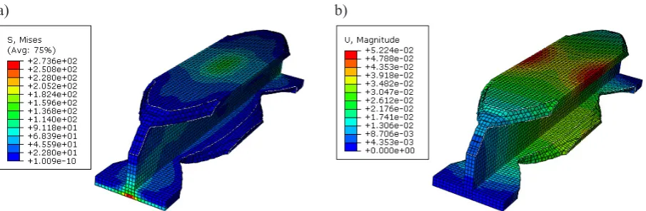
The numerical analysis enabled determina-tion of the distribudetermina-tion of stresses and displace-ments that occur in the model prior to and after the optimization process. The boundary condi-tions and continuous load in the form of pressure applied to the FEM model enabled generating vi-sualization of stresses and displacements within the entire model. The distribution of stresses and the displacements prior to optimization are illus-trated below (Fig. 4).
The numerical results demonstrate that the reduced stresses amount to 261 MPa at a dis-placement of 0.05 mm. Under the applied pres-sure the beam does not work in an elastic range as was the case with the preload because the yield point is significantly exceeded. The sym-metric bending of the profile enabled determina -tion of special areas of the structure where the state of stress is practically insignificant. These
Fig. 3. Preparation of numerical analysis of a model: a) boundary conditions, b) finite element mesh
areas are located in the region of upper shorter and lower longer edges of the beam and they are marked in blue. The highest stresses occur in the key parts of the I-section profile, i.e. in its central regions which are fully fixed by the boundary conditions defining the lower edges. The highest displacements can be observed in the region of applied load. The topology optimization analy-sis was characterized by the ”freezing” of re-gions described by the boundary conditions and the applied pressure. This means that neither the edges nor the plane under load can be subjected to any optimization processes, as they are essen-tial to the profile’s work. The idea of optimiza-tion was to reduce material volume in the region characterized by low bending susceptibility. The applied topology optimization criteria were only supposed to ”slim down” the structure without smoothing its shape.
The numerical results right after optimization are shown in a figure given below (Fig. 5).
The numerical results demonstrate that to-pology optimization is a very promising process. Decreasing the structure’s volume by 25% will undoubtedly help reduce both production costs
and structure weight. Both the pre- and post-optimization results demonstrate that the pro-file’s displacement is 0.05 mm and the stresses are nearly 261 MPa (before optimization) and 274 MPa (after optimization), respectively. The level of stresses after optimization increased only by about 5%, which is still a remarkably good result given such a high reduction in volume of the parent material. The paper investigates only the benefits resulting from the use of numerical analysis programs in order to focus on a design and production process. The result is not however final and cannot be used to define a technological process, as it only presents the potential of gener-ating optimal solutions of structure design for a set of given criteria (describing whether selected parameters vary or remain constant). The inves-tigations described in the paper were conducted using one numerical simulation program based on the finite element method.
Topology optimization is just a preview of the potential which could be reached by apply-ing other optimization criteria such as part shape optimization to increase strength and mechanical properties of the structure.
Fig. 4. Numerical results prior to topology optimization: a) stress, b) displacement
a) b)
Fig. 5. Numerical results after topology optimization: a) stress, b) displacement
CONCLUSIONS
Numerical analysis is a perfect alternative to experimental and analytical investigation. The finite element method is a fast numerical tool for solving both simple and complex problems. Compared to traditional methods for determining stress, strain and displacement, FEM is a promis-ing tool with great potential for development and it is currently used by engineers to enhance com-putational processes.
The use of optimization opens up new pos-sibilities of improving structures as early as at the stage of their design.
Given the scarce number of publications devoted to the problem of topology optimi-zation by the finite element method, it seems necessary to gain experience and conduct re-search on this field.
The numerical analysis led to the formula-tion of the following conclusions:
• topology optimization by the finite element method enables illustrating the results of opti-mal solution depending on preset parameters, • the results prior to and after optimization can
intuitively help determine process quality, • topology optimization generates only an
ap-proximate shape of the desired structure with im-proved properties (e.g. mechanical properties), • reduction of structure volume can often lead
to a slight increase in stresses, which can oc-cur right after topology optimization, which – in many cases – has no negative effect given the satisfactory results of making the profiles ”thinner” and reducing their weight.
Numerical analysis is a very efficient and ac -curate process which can provide desired results, depending on what is required.
Numerical analysis systems are a powerful tool that enhances the stage of structure design. Although there are many FEM-based systems available on the market, Abaqus is one of a few systems which can define almost every problem based on physical, chemical as well as mechani-cal processes. The results of topology optimiza-tion for a beam subjected to bending demonstrate not only the applications for FEM but also point to the necessity of developing optimization pro-cesses focusing on the technological aspect of manufacturing.
REFERENCES
1. Arjmandi H.R., Amani E.: A numerical investiga-tion of the entropy generainvestiga-tion in and thermody-namic optimization of a combustion chamber. En-ergy, 2015, vol. 81, 706–718.
2. Azadi R., Rostamiyan Y.: Experimental and analyt-ical study of buckling strength of new quaternary hybrid nanocomposite using Taguchi method for optimization. Construction and Building Materials, 2015, vol. 88, 212–224.
3. Huang B., Kanemoto T.: Multi-objective numerical optimization of the front blade pitch angle distribu-tion in a counter-rotating type horizontal-axis tidal turbine. Renewable Energy, 2015, vol. 81, 837–844. 4. Kundu B., Barman D.: An analytical prediction for
performance and optimization of an annular fin as -sembly of trapezoidal profile under dehumidifying conditions. Energy, 2011, vol. 36, 2572–2588.
5. Lonkwic P., Różyło P., Dębski H.: Numerical and
experimental analysis of the progressive gear body with the use of finite-element method. Eksploatac -ja i Niezawodność – Maintenance and Reliability, 2015, 17(4), 544–550.
6. Markus D., Ferri F., Wüchner R., Frigaard P.B., Bletz -inger K.-U.: Complementary numerical-experimental benchmarking for shape optimization and validation of structures subjected to wave and current forces. Computers & Fluids, 2015, vol. 118, 69–88. 7. Najafia A.R., Safdaric M.D.A., Tortorellia D.A.,
Geubellec P.H.: A gradient-based shape optimiza-tion scheme using an interface-enriched general-ized FEM. Computer Methods in Applied Mechan-ics and Engineering, 2015, vol. 296, 1–17. 8. Wang J., Lan S., Chen T., Li W., Chu H.: Numeri
-cal simulation and combination optimization of aluminum holding furnace linings based on
simu-lated annealing. Chinese Journal of Chemical En
-gineering, 2015, vol. 23, 880–889.
9. Wang W., Clausen P.M., Bletzinger K.-U.: Im -proved semi-analytical sensitivity analysis using a secant stiffness matrix for geometric nonlinear shape optimization. Computers and Structures, 2105, vol. 146, 143–151.
10. Zienkiewicz O.C., Taylor R.L.: Finite Element Method (5th Edition) Volume 2 – Solid Mecha-nics, 2000, Elsevier.
11. Abaqus HTML Documentation.
12. Material properties, http://www.splav-kharkov. com/en/e_mat_start.php?name_id=881.
![Fig. 1. Example of structure topology optimization [13]](https://thumb-us.123doks.com/thumbv2/123dok_us/8808985.1776149/2.595.92.510.582.751/fig-example-of-structure-topology-optimization.webp)