Volume 01, No. 9, September 2015
P
age
26
Development of Double Point Cutting Tool for Boring Operation
Robin M Cherian*, K. Santhosh Kumar**, Raja Mohan***
*M.Tech Student, Sree Buddha College of Engineering, Pattoor.
**Scientist/Engineer, Vikram Sarabhai Space Centre, Trivandrum
***Assistant Professor, Sree Buddha College of Engineering, Pattoor.
ABSTRACT
Machining is the most widely known metal removal process in manufacturing. Boring is the process of enlarging a hole that has already been drilled by a single point cutting tool. At present, in machine shops jobs that require high surface finish are realized in two stages. They are (i) boring the internal diameter of the job (ii) finishing the job to its final size within that tolerance range by removing the stock given in the boring operation. The present method practiced will result in draw backs like setting errors, queuing of jobs and schedule delay (“Bottle Neck”) and additional finishing operations adds up cost also. To overcome the drawbacks of conventional method practiced, and to enhance the surface qual i t y , a new idea of modifying internal turning tool (single point cutting tool) with an additional cutting edge is proposed, so that finishing operation can be done in lathe itself.
Keywords: Single point cutting tool, Surface finish, Taguchi based GRA, Boring operation
INRODUCTION
Machining operations have been the center of attraction of the manufacturing industry since the revolution of industries. Increasing the productivity and the quality of the machined parts are the main challenges of metal-based industry. In modern industry the goal is to manufacture low cost, high quality products in short time. In applications where surface finish is important to the functioning of a device such as in face seals, ball bearings, gears, cam surfaces, or journals, it is found that performance varies logarithmically. This means that for there to be a twofold improvement in performance, there must be tenfold reduction in surface roughness. Therefore surface must be carefully finished. In aerospace and medical
fields, the surface finish of a machined component is of utmost importance. Boring can be
viewed as the internal-diameter counterpart to turning, which cuts external diameters and is a very important machining operation. At present, kind of jobs that requires high surface finish are realized in two stages as explained below
1. Boring : Turning the ID of the jobs with allowance in the range of 50 microns for
finishing in grinding operation
2. Grinding/Honing/Reaming: Finishing the job to its final size within the tolerance
Volume 01, No. 9, September 2015
P
age
27
Drawbacks of the present method practiced are:
a. Since the jobs are done in two different machines the setting errors may prevail
b. There is only one grinding machine available and queuing of jobs for grinding will
result in schedule delay. (Bottle neck)
c. The available grinding machine is 30 years old and having frequent breakdowns
which further delays the component realisation.
To overcome the drawbacks of conventional method practiced, the “bottleneck” and to enhance the surface quality, an attempt is made to modify single point cutting tool so that finishing operation can be done in lathe itself.
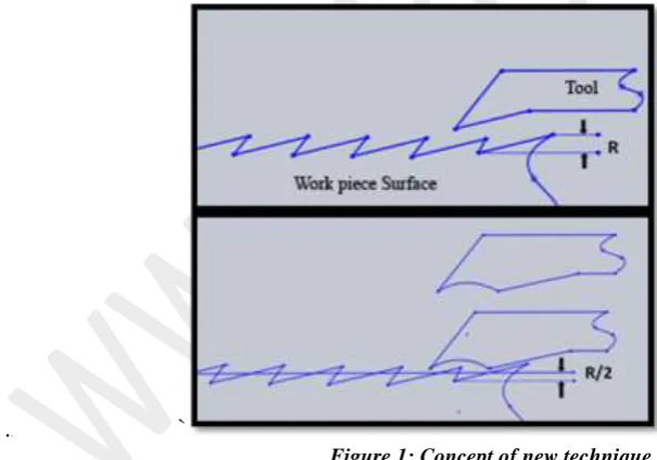
DOUBLE POINT CUTTING TOOL- THE IDEA
Two simultaneous pass with second pass having zero depth of cut will improve the surface finish. The drawback of this technique is that the time taken for its two passes represents twice the time of regular machining. Another drawback is the difficulty of adjusting the tool in the second pass with the appropriate accuracy. For solving these problems, a tool design is proposed to achieve results of the two-pass in one pass.
In the proposed technique, the single point cutting tool will be modified. The tool will have two cutting edges; the first one will be for cutting operation and next one for finishing operation. So that surface roughness will be reduced in the single operation itself. Boring is started with the first cutting edge with certain cutting conditions and depth of cut. The second cutting edge is for finishing operation, with zero depth of cut
. `
Figure 1: Concept of new technique.
From Fig 1 it is clear that surface roughness will be almost reduced by 50% by the newly proposed technique. It can be achieved in the single operation (i.e. single pass) itself, so it would be the cost and time efficient one
Volume 01, No. 9, September 2015
P
age
28
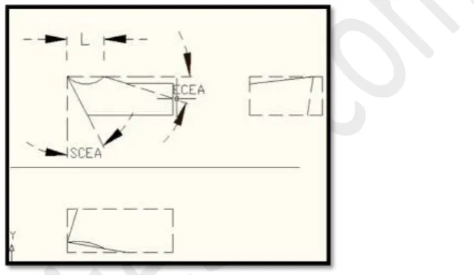
From the literature survey and observation, we have observed that, 4 factors contribute significantly to the surface finish. They are:
Distance between the 2 cutting edges (L) End cutting edge angle (ECEA)
Nose radius
Side Cutting Edge angle (SCEA)
Nose radius is generally taken as 0.2 mm for most of the tool although it can be varied in the range from 0.2 mm to 2.4mm. Since the new tool is developed by grinding, grinding of nose radius to such small value is difficult. So we will keep nose radius for two cutting edges constant.
Figure 2: CAD drawing of modified tool
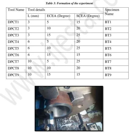
There are 3 parameters whose influence we want to study and the range of these parameters are divided into 3 levels, the range of length is selected based on practical considerations. Various levels for the parameters are given in Table 1.We are following Taguchi L9 orthogonal array for design of experiment, so 9 cutting tool with specification as shown table 3 is to be made
Table 1: Setting of levels
Level Length (L) End cutting edge angle
(SCEA)
Side Cutting Edge Angle
(SCEA)
1 3 5 15
2 6 10 20
3 10 15 25
DEVELOPMENT OF MODIFIED TOOL
Volume 01, No. 9, September 2015
P
age
29
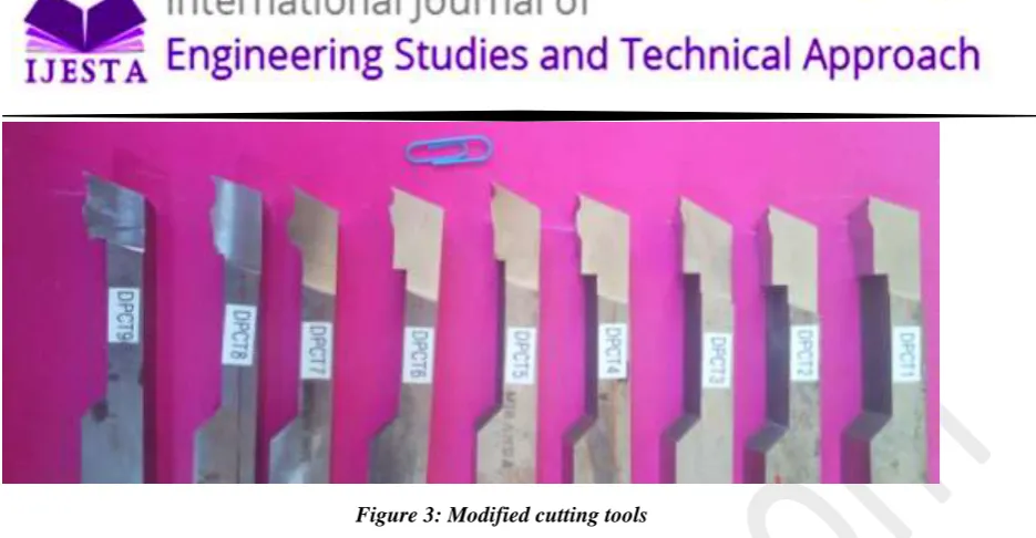
Figure 3: Modified cutting tools
Thus after extensive grinding process the tool was developed. The new tools are shown in the figures 3
Signal to noise ratio
There are 3 Signal-to-Noise ratios of common interest for optimization of problems which depend on the objective function
Smaller-the-better
η = -10 Log10 [mean of sum of squares of measured data]
This is usually the chosen S/N ratio for all undesirable characteristics like "defects" etc. for which the ideal value is zero. Also, when an ideal value is finite and its maximum or minimum value is defined (like maximum purity is 100% or maximum Tc is 92K or minimum time for making a telephone connection is 1 sec) then the difference between measured data and ideal value is expected to be as small as possible. The generic form of S/N ratio then becomes,
η = -10 Log10 [mean of sum of squares of {measured - ideal}]
Larger-the-better
η = -10 Log10 [mean of sum squares of reciprocal of measured data]
This case has been converted to SMALLER-THE-BETTER by taking the reciprocals of measured data and then taking the S/N ratio as in the smaller-the-better case.
Nominal-the-best
This case arises when a specified value is MOST desired, meaning that neither a smaller nor a larger value is desirable
OPTIMIZATION OF TOOL PARAMETERS OF DOUBLE POINT CUTTING TOOL
Volume 01, No. 9, September 2015
P
age
30
Table 2 Experimental Setup for phase 3
Experimental set up Specifications
Work piece material 15CDV6, Internal diameter -70 mm(approx.), External
diameter-94mm ,length-50mm
Machine used HMT NH 26 (CNC Retrofitted)
Cutting tool Newly developed tools (9 nos.)
Cutting condition V=30m/min, f=0.05mm/rev, d= 0.5mm
Coolant used Water + soluble oil
Table 3: Formation of the experiment
Tool Name Tool details Specimen
Name
L (mm) ECEA (Degree) SCEA (Degree)
DPCT1 3 5 15 BT1
DPCT2 3 10 20 BT2
DPCT3 3 15 25 BT3
DPCT4 6 5 20 BT4
DPCT5 6 10 25 BT5
DPCT6 6 15 15 BT6
DPCT7 10 5 25 BT7
DPCT8 10 10 20 BT8
DPCT9 10 15 15 BT9
Volume 01, No. 9, September 2015
P
age
31
S/N ratio for each reading is obtained by using the formula as described above. Since our objective function is surface roughness smaller the better characteristics is used
Table 4: Average Ra values and S/N ratio
Specimen Name
Ra VALUE(microns) Average Ra
Value (microns) S/N Ratio (η)
Location 1 Location 2
BT1 2.90 3.55 3.23 -10.2272642
BT2 2.96 3.33 3.15 -9.9818176
BT3 3.29 3.16 3.23 -10.1857873
BT4 2.7 2.5 2.65 -8.47186064
BT5 2.72 2.83 2.78 -8.88263275
BT6 3.16 3.03 3.1 -9.82897071
BT7 6.25 5.54 5.9 -15.4326468
BT8 3.24 3.51 3.38 -10.5852772
BT9 3.19 3.46 3.33 -10.4558278
Table 5: Average S/N ratio for each parameter at three levels
Symbol Process Parameter Roughness value(microns)
Low Medium High
L Length -10.1316 -9.06115* -12.1579
ECEA End cutting edge angle -11.3773 -9.81658* -10.1569
SCEA Side Cutting Edge angle -10.2138 -9.6365* -11.5004
*Optimized Level
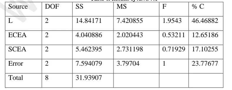
ANALYSIS OF VARIANCE (ANOVA)
The purpose of analysis of variance (ANOVA) is to investigate which of the tool parameters significantly affect the performance characteristics.
Table 6. Results of ANOVA
Source DOF SS MS F % C
L 2 14.84171 7.420855 1.9543 46.46882
ECEA 2 4.040886 2.020443 0.53211 12.65186
SCEA 2 5.462395 2.731198 0.71929 17.10255
Error 2 7.594079 3.79704 1 23.77677
Volume 01, No. 9, September 2015
P
age
32
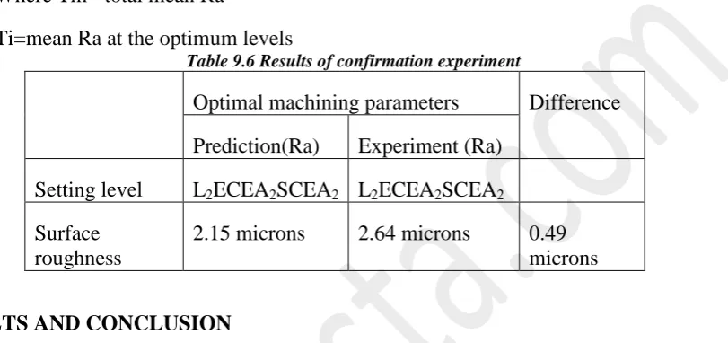
CONFIRMATION TEST
After evaluating the optimal parameter settings, the next step is to predict and verify enhancement of the quality characteristics using optimal parametric combination. The prediction equation is given by
Tʹ ʹ =Tm+∑ (Ti-Tm)
Where Tm= total mean Ra
Ti=mean Ra at the optimum levels
Table 9.6 Results of confirmation experiment
Optimal machining parameters Difference
Prediction(Ra) Experiment (Ra)
Setting level L2ECEA2SCEA2 L2ECEA2SCEA2
Surface roughness
2.15 microns 2.64 microns 0.49
microns
RESULTS AND CONCLUSION
The idea of double point cutting tool for boring operation was proposed and nine tools with varying combination of tool parameters are developed to find out the optimized tool
parameters using L9 orthogonal array and the optimized levels are L=6mm,ECEA=200 and
SCEA=100. By Performing ANOVA it has been found out that the most influencing factor in
surface finish is Length between two cutting edges. In order to compare the performance of the new optimized tool,a single point cutting tool wasground with all the other parameters (rake angle etc.) same as that of optimized double point tool as shown in figure 5. Now two specimens are bored using the two tools and its surface finish was noted. The surface finish of single point and double point tools are 3.07 and 2.64 microns (Ra value) respectively
.
Volume 01, No. 9, September 2015
P
age
33
From the readings it has been understood that surface finish have been increased by 14%. The obtained result is very low compared to our expected increase in performance by 50%. The reasons for this difference may be
Vibration induced due to weakening of tool due to material loss Lack of control over tool nose radius
Incorrect tool setting: Tool wear
REFERENCES
i. M. Dogra,V. S. Sharmab, J. Durejac, (2011), “ Effect of tool geometry variation on
finish turning”,Journal of Engineering Science and Technology Review, pp 1-13,
ii. T M El-Hossainy, Enhancement of surface quality using a newly developed technique
in turning operations, Department of Industrial Engineering, King Saud University, Riyadh, Saudi Arabia.
iii. Roy, R.K., 1990, “A Primer on the Taguchi method”. Competitive Manufacturing
Series, Van Nostrand Reinhold, New York.
iv. Lin W. S., Lee B. Y., Wu C. L, “Modeling the surface roughness and cutting force for
turning”, Journal of Materials Processing Technology, Volume 108, 2001, pp. 286293
v. Thamizhmanii S., Saparudin S. and Hasan S, “Analysis of Surface Roughness by
Using Taguchi Method”, Achievements in Materials and Manufacturing Engineering,
Volume 20, Issue 1-2, 2007, pp. 503-505.
vi. Reddy B. S., G. and Reddy K. V. K Padmanabhan, “Surface Roughness Prediction
Techniques for CNC turning”, Asian Journal of Scientific Research, Volume 1,
Number 3, 2008., pp. 256-264
vii. R.K. Jain, Production Technology: Manufacturing Processes, Technology and