Issues with Exchange of Presentation Data Among CAD Systems
Giedrius Liutkus, Aleksas Riškus, Arnas Tomkeviius,
Antanas Lenkeviius
Multimedia Engineering department, Kaunas University of Technology Student St. 50, LT51368 Kaunas, Lithuania
E-mail:[email protected], [email protected], [email protected], [email protected]
http://dx.doi.org/10.5755/j01.itc.41.4.834
Abstract. Today exchange of data among CAD systems becomes more important. As each CAD system has its own flavor to represent the same objects, exchange of data among them is full of issues. Most common problems are incomplete transfer of presentation information, associativity between representation and presentation, usage of annotation planes and text. They are analyzed in details and possible solutions are suggested as well.
Keywords: data exchange; STEP; data models; GD&T; presentation; representation.
1. State of the art
The exchange of the data generated by different CAD systems emerged few decades ago. Initially IGES was used as intermediate format [1]. Later it was superseded by STEP [14], [19], [21]. STEP is gaining popularity for database applications [6]. But we will not address this in the paper. So far only geometry and topology was exported and imported from STEP into and from CAD systems. Just recently the scope of this exchange started to constantly grow [8], [9]. One of the vehicle for this process is CAx-IF (CAx Implementors Forum) [3]. It is a collaboration organization enabling easier way to exchange the data among CAD systems. Collaborative design and planning is more and more recognized as an important topic [20]. This group also defines common under-standing and usage of the same data structures. As mentioned above, STEP serves well as a common data structure for geometry and topology. This is well recognized by the industry, but no longer satisfying all the needs. CAD systems are extending the usage of STEP to also exchange presentation data (colours, transparency, curve thickness, etc.), validation proper-ties (test points, volume, surface area, etc.), construc-tion history, GD&T, etc. Integraconstruc-tion of STEP and OWL is another application area [18]. The usage of the new standards from STEP (even if they are defined some time ago) causes some problems and they have to be tackled. In this paper we will try to highlight
some of those issues. We will try to provide possible solutions as well.
2. Issues
The main reason for the appearance of the problems with exchange of the data generated by different CAD systems – different tools do the same things differently. The same applies to the storage of the data. The main task of this article is determining common principles and data structures for CAD systems and providing suggestions how to use them. Issues arising here are described in next subsections.
2.1. Presentation versus Representation
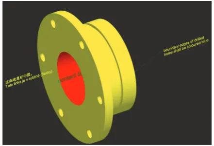
Representation data are exchanged among CAD systems since appearance of IGES standard [1]. In principle, geometrical/topological structures like A-BREP, CSG, etc. fall under this category. For example, if we have an edge implemented as a circular arc, then it is called ‘representation’ of the curve. Assume one wants to display e.g. the radius of that arc on the screen. That is called ‘presentation’ of that curve. Ane example of representation and presentation is provided in Figure 1.
presentation data. This example is one of the first test cases provided by CAD systems via CAX-IF organization mentioned above to the public [16]. In this particular test case some features (like through holes) and faces are colored specifically (blue and red, respectively). This is also noted in additional text provided on the picture in various languages. The very first example stored in STEP containing presentation data is provided in [2]. Besides simple cube it also includes leader directed callout – simplest possible callout, which is a kind of annotation to the model.
In general, presentation should be treated as auxiliary option to its representation. But if presen-tation is available, it should be presented to the end user. Summarizing, we can say that representation is more computer sensible than presentation and is used by CAD tools or viewers to represent particular 3D model. Presentation is the way how to style available
CAD systems provide capabilities to calculate dimen-sions (in this case “76.64”) automatically from the data. If a CAD system is also capable to automatically update this value when original data (in this case – the length of the curve) are changing – it is implementing the needed relationship between representation and presentation of a dimension. Usually this is not the issue within CAD system itself. It becomes proble-matic when one needs to exchange a property between different CAD systems. As described earlier, CAD systems use basically the only way to exchange data – they use STEP. So it is important that STEP data models are well defined, easy to understand and maintain. In order to realize associativity between presentation and representation within STEP – rather complex structure has to be handled. An example of this structure is provided in Figure 3.
Figure 3. Example of associativity between a portion of the geometry (edge_curve) and the annotation (draughting_callout) using the old approach
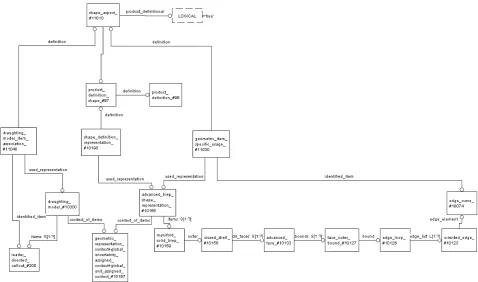
Figure 4. Example of associativity between the portion of the geometry (edge_curve) and the annotation (draughting_callout) using the new approach
Detailed GD&T representation and presentation data are linked by shape_aspect_associativity
(#11000). The ‘related’ shape_aspect (#11020) captures the portions of a geometric model being asso-ciated with annotation. The ‘relating’ shape_aspect
(#11010) captures the annotation elements being
associated with elements of the geometric model (#11011). Both shape_aspects have to share the same
product_definition_shape (#97). This diagram shows the way to associate leader_directed_callout (#200) with edge_curve (#10074) it is representing. Besides
mentio-one – item_identified_representation_usage. In the case of previously provided example, instead of having 6 intermediate entities we have only 2
item_identified_representation_usage (#11030 and #11040 entity instances). So when this new pattern is allowed by Application Protocol [17] – it is recommended to use it (Figure 4) rather than the pattern provided in Figure 3. In order to distinguish
item_identified_representation_usage used to link
draughting_model from the one pointing to geometric model (in this case, A-BREP), 2 specific subtypes were introduced: draughting_model_item_association
and geometric_item_specific_usage, respectively. Only relatively recently CAD systems started to fully model annotations and all GD&T presentation data in 3D. This causes more issues to resolve. It
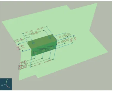
‘mathematical’ plane, which is infinite. This becomes a problem when some tool needs to display an anno-tation plane on the screen. Therefore CAD systems are encouraged to always generate a bounding box for an annotation plane. In Figure 5 annotation planes are bounded according to the dimensions of the whole 3D object. Sometimes even those dimensions are not sufficient – some annotation (on the left part of Figure 5) may fall outside of the annotation plane. As mentioned above, a possible solution is that the source CAD system (which generated the data originally) should provide explicit bounding box.
Figure 6. STEP data model linking annotation_plane with its orientation and position
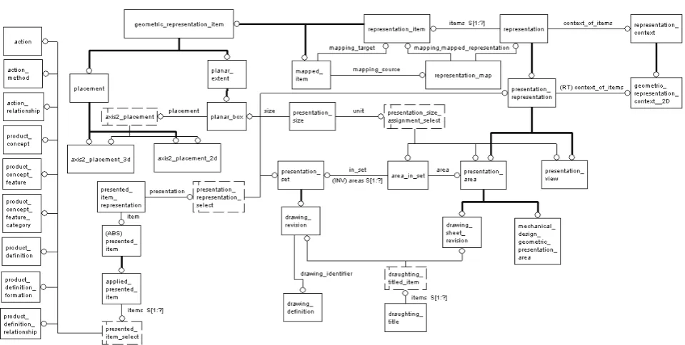
Figure 7. The data model for the draughting and annotation area in STEP
Unfortunately, CAD system usually does not specify the size explicitly. The centering of an annotation plane is also an issue with most of the files provided by the tools. STEP provides an explicit way to specify that center point. The data model is shown in Figure 6. Here EXPRESS-G diagram presents links among annotation_plane, plane, axis2_placment3d
and finally cartesian_point. CAD tools usually set that
cartesian_point, but it is only a point on a plane. It is not a center point of an annotation plane to be displayed. In the case planar_box is not provided as suggested above, receiver has to deal with inomplete data and try to display annotation_plane in the best possible way. The proposed algorithm goes as follows:
1.Calculate the center point of a 3D object/scene.
2.Project that center point onto an
annotation_plane.
Newly calculated projection point is the center point needed for displaying of an annotation_plane.
2.3. Polyline approach vs semantic approach
‘A’ to ‘B’, the user would need to find and delete at least 3 line segments corresponding to the letter ‘A’ and add line segments needed to represent the letter ‘B’. This is very tedious and surely not practical way to implement editing.
Figure 8. The data model for the 'polyline approach'
Figure 8. The data model for the 'polyline approach'.One of the most problematic areas of the data exchange between CAD systems is text. Although the exchange of the character sets looks simple, problems arise when we start to talk about the correct font, its size, special symbols, etc.
First of all, different CAD systems have different, usually proprietary fonts. So transferring of characters “ABC” defined by font “X” into another CAD system having no such font is problematic. The same text represented in different fonts will look different. It becomes very problematic when text has to exactly fit into specific box or frame (which is very often used in GD&T area). Figure 9 contain a typical example of the problem mentioned above. The font issue is recognized and realized by CAD vendors.
Figure 9. Example of the issue to fit the text into the GD&T frame
character’s string. The problem here is that a producer has to calculate the bounding box of each character’s
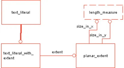
Figure 10. The data model specifying the text size in STEP
string. The worst – a receiver is not getting the font size. It is getting only that bounding box. The easiest solution is to get the text height and treat it as a font size. In most of the cases it is approximately correct solution. If a receiving system does not have the font generated by a source system, usually a text in a receiving system will look shorter or longer than in a source system. Figure 9 provides such an example. The bottom line of the text more or less precisely fits into the bounding box, but the width of the text is almost two times shorter than it was originally defined. Unfortunately, there is no easy solution here. This simply means that a font in a source system is much wider than a font in a receiving system. A receiving system has to find a font which is the best approximation of the font used in a source system. STEP is used here as an intermediate format and it does not provide ability to exchange more font characteristics. So finding the font ‘X’, which is semantically closer to the font ‘Y’ is almost a pure ‘try and test’ task.
3. Conclusions
There are many issues with the exchange of presentation and representation data in CAD systems. Unfortunately, most of the issues are different in nature and have to be tackled individually. This article provided suggested solutions for the most popular
issues. Some of the solutions required to change standards within STEP. We contributed to those changes as well. Some of the issues (like the text font and size issue) can’t be fully fixed today. So we provided recommendations how to minimize bad consequences of the data exchange.
References
[1] ANSI/US PRO/IPO 100-1996-Initial Graphics Exchange Specification (IGES). ANSI, 1996.
[2] Callouts. Leader directed callout. Resource site:
http://www.wikistep.org/index.php/Callouts#Leader_di rected_callout.
[3] Cax Implementor Forum. Resource site: http://www.cax-if.org.
[4] CAx-IF Recommended Practices for the Representation and Presentation of Product Manufacturing Information (PMI). Resource site:
http://www.cax-if.org.
[5] P. Chiabert, F. Lombardi, M. Orlando. Benefits of geometric dimensioning and tolerancing. Journal of
Materials Processing Technology, Vol. 78, Issues 1–3,
1998, 29–35.
[6] Y. Dong, C. F. Y. Chee, Y. He, A. Goh. Active data-base support for STEP/EXPRESS models. Journal of
Intelligent Manufacturing Vol. 8, No. 4 (1997),
251-261, http://dx.doi.org/10.1023/A:1018581426556. [7] B. R. Fischer. Mechanical tolerance stackup and
analysis. In: CRC Press, 2011, http://dx.doi.org/10.1201/0894.
[8] G. Liutkus, J. Matickas. An Algorithm Specialised for Mapping of Electronic Components onto 3D Objects. Information Technology and Control, 2005,
Vol. 34, No. 4, 377 – 384.
[9] G. Liutkus, K. Rudokas, A. Barila. Topological Structures in Printed Circuit Boards and Assemblies.
Information Technology and Control, 2002, No. 3(24),
55 - 64.
[10] ISO-10303-11. Industrial automation systems and inte-gration–Product data representation and exchange–Part 11: Description methods: The EXPRESS language reference manual.
[11] ISO/DIS 10303-101. Product data representation and exchange: Integrated application resource: Draughting. [12] ISO 16792. Technical product documentation—
Digital product definition data practices.
[13] ISO-3098. Technical product documentation— Lettering — Part 0: General requirements.
[14] S. J. Kemmerer. STEP. The Grand Experience. Manufacturiing Engineering Laboratory, NIST, 1999. [15] V. Srinivasan. Standardizing the specification,
verification, and exchange of product geometry: Research, status and trends. Computer-Aided Design,
Vol. 40, Issue 7, 2008, 738–749. http://dx.doi.org/10.1016/j.cad.2007.06.006.
[16] STEP File Library. Resource site:
http://www.caxif.de/library/index.html. [17] STEP Tutorial. Resource site:
http://www.wikistep.org/index.php/STEP_Tutorial. [18] E. Vyšniauskas, L. Nemurait, R. Butleris,
B. Paradauskas. Reversible Lossless Transformation from OWL 2 Ontologies into Relational Databases. In:
Information Technology and Control, 2011, 40(4),
293–306, http://dx.doi.org/10.5755/j01.itc.40.4.979. [19] X. Xu, A. Y. C. Nee. Advanced design and
manu-facturing based on STEP. Springer, 2009,
http://dx.doi.org/10.1007/978-1-84882-739-4.
[20] L. Wang, A. Y. C. Nee. Collaborative design and planning for digital manufacturing. Springer, 2009,
http://dx.doi.org/10.1007/978-1-84882-287-0.
[21] Y. F. Zhao, S. Habeeb, X. Xu. Research into integrated design and manufacturing based on STEP.
The International Journal of Advanced Manufacturing
Technology, Vol. 44, No. 5-6 (2009), 606-624,
http://dx.doi.org/10.1007/s00170-008-1841-6.