DISCOVERY OF MODEL IMPLEMENTATION PATTERNS IN
SOURCE CODE
Linas Ablonskis, Lina Nemurait
ė
Kaunas University of Technology, Department of Information Systems Studentų st. 50-308, LT-51368 Kaunas, Lithuania
linas.ablonskis@stud.ktu.lt, lina.nemuraite@ktu.lt
Abstract. We present a language independent method for detecting model implementation patterns in a source code.In contrast to most other reverse engineering methods, we exploit existing program model for this purpose. Our method works by recognizing instances of simple model-to-code transformations. The patterns we use for recognition of model elements can be reused for composing templates for generating a program code. Our method is used for recognizing relationships between program model and handwritten program code.
Keywords: reverse engineering, code generation, UML, MDA, abstract syntax tree, implementation patterns.
1. Introduction
Incorporation of abstract models into software development has become a widely accepted practice. There are several software development paradigms such as Model Driven Architecture MDA) [1], Model Driven Engineering (MDE) [2] and Model Driven Development (MDD) [3] that use software models not just for documentation but as one of central artifacts during software development process.
When developing software based on abstract mo-dels it is beneficial to use program code generators [4] to quickly generate repetitive parts of a source code from program models. Usually, it is possible to make a program model in the initial steps of the software de-velopment cycle, but generating a source code from that program model is not always practical [4]. This happens when the software is being implemented in a domain that is not understood well enough to write the corresponding program code generator. This also happens when implementation platform changes too quickly to become a stable enough target for program code generation.
To rectify this situation we proposed a program code generator that automatically configures itself to generate program code from a given program model while observing partial implementation of that prog-ram model by a human [5]. In order to achieve this, we need to relate program model and handwritten program code. We present such a method in this paper. Our method works by recognizing the application of simple model-to-code transformations in a given source code. In contrast to most other reverse
engineering methods, we exploit existing program model for reverse engineering; furthermore, the pat-terns we use for recognition of model elements can be reused for composing templates for generating a prog-ram code.
The reminder of this paper is structured as follows: in Section 2 the related work is considered; in Section 3 the method for finding model implementation pat-terns in a source code is presented; Section 4 demonst-rates an example of applying the method and Section 5 is used to draw conclusions and outline future work.
2. Related works
Program code generators are used to generate program code from abstract program models. There are various types of abstractions used in modeling program structure and behavior such as enterprise mo-dels expressed in UML [6], populated business rule templates [7], domain rules extracted from ontologies [8], UML OCL statements [9], etc. Various program code generators belong to the field of metaprogram-ming [10] and are used for generating more specific program code from more abstract program code. For the purposes of this paper, we understand program models as being on the level of abstraction that corres-ponds to UML [11] class models with such elements as packages, classes, stereotypes and related structural concepts.
engineering is quite wide and includes such areas as re-documentation, architecture recovery, design reco-very, design pattern recoreco-very, program visualization and understanding, code metrics and source code ana-lysis, reengineering, and refactoring. We found the most related works in areas of design recovery, design pattern recovery and reengineering.
Techniques for analyzing source code raise the level of abstraction of a source code being analyzed. However, this level at most corresponds to the level of object oriented or functional programming concepts [16]. This makes them not suitable for reverse engi-neering to the level of abstractions used in MDA. Abstractions used in MDA are best represented by the concepts of UML language.
Most reverse engineering tools and methods [17– 23] follow a well-defined pattern of operation. They parse a given source code to the level of abstraction that is somewhere near Abstract Syntax Tree (AST). They optionally resolve dependencies and entities. Then this information is written to the database where a set of extractors are run that extract a set of pre-dicates and also write them to the database. After that, a set of analyzers are run to produce some results, or querying of source code related facts can be perfor-med. Those reverse engineering tools and methods are primarily designed to extract code metrics, facts or code artifacts for the tasks of system architecture recovery, program comprehension or reengineering. This makes them unsuitable for our needs. Code met-rics and facts are just code artifact related measures. Code artifacts are at too low level of abstraction com-pared to MDA artifacts. Architecture recovery is often speculative and primarily produces such abstractions as possible modules of source code or possible boundaries of components with interfaces. Those abst-ractions are too vague for our purposes.
UML Computer Aided Software Engineering (CASE) tools employ the same reverse engineering methods as everything else, but they produce UML artifacts as a result. Static code analysis allows pro-ducing class models [24]; dynamic analysis of execu-tion traces creates sequence diagrams and other beha-vioral artifacts [25]. There are attempts at creating round-trip engineering environments in UML CASE tools. One such attempt was done using FUJABA and employing code annotations in code comments for producing UML story diagrams (story diagram is a custom diagram type that merges collaboration and activity diagrams [26]). The methods used in produc-ing class models parse program code into AST (or partial AST omitting unnecessary elements) and then apply pattern detection algorithms to produce class models. This kind of reverse engineering requires creating a custom detection pattern for each artifact to be recovered. However, these detection patterns can-not be used to generate source code, unlike the ones used in our method.
A notable piece of work in MDA related reverse engineering is described in a 2008 paper by Bork et al.
[27]. They have created a method that allows analyz-ing generated source code and recognizanalyz-ing the temp-lates that were used to generate it. Once temptemp-lates are found and data tokens are extracted, a set of case-by-case converters are used to convert those tokens back into UML models. The main benefit of this method is that the same template is used for generation of source code and reverse engineering. This reduces the main-tenance work of a CASE tool.
The method works by parsing a template and split-ting source code into words. The template is then matched token-by-token to the source code with some look ahead. Variables are filled and all logical branches are considered. A constraint solver is used to decide what template branches satisfy the code being matched by the variables employed for branching. Hints are used to help matching variables. After temp-lates are matched, an intermediate data layer is const-ructed from the data extracted into template variables. A set of case-by-case converters then work on the intermediate data layer and convert it back into UML model. The technique is independent from source code language; however, it cannot recognize reordered code. This prevents it from being used for reverse en-gineering handwritten program code. It also cannot reverse engineer templates directly into UML model elements.
Another piece of work that strongly relates to ours is described in a 1990 paper by Rich and Wills [28]. They have created a method that allows recognizing a presence of design concepts or techniques in source code. This is done by parsing source code and creating an attributed flow graph where nodes represent struc-tural artifacts and edges represent control or data flow between the nodes. Artifacts to be recognized are en-coded as pieces of flow graphs and make a graph grammar. A special algorithm [29] is used to parse a flow graph and recognize elements of a graph gram-mar, thus recognizing related artifacts. While this algorithm cannot relate a program model and source code, a chosen approach of artifact recognition is very close to one employed in our work in a sense that they do not employ special scripts or case-by-case algo-rithms to recognize artifacts, but describe artifacts in the form they are found in abstracted source code and use this information for recognition.
Some methods use additional dynamic analysis to extract execution traces or call graphs. These data are then analyzed by a set of predefined algorithms where each algorithm is tailored for detecting one design pattern [31, 32]. Another method for recognition of design patterns [33] uses graphs to describe design pattern templates like the reverse engineering method mentioned before [28]. An algorithm that evaluates edge similarity of two graphs [34] is then used to finding correspondences between templates of design patterns and a tree composed of elements of a source code.
There is a way to accelerate design pattern detec-tion by fingerprinting them with a set of code metrics (size, filiation, cohesion and coupling) and then using those code metrics to quickly reject design pattern candidates before employing standard detection tech-niques [35]. This requires a rule engine and an initial source code base for teaching that rule engine. Simi-larly, there is a method that uses decision trees and neural networks for recognizing design patterns through code metrics [36]. Since it employs a neural network, this method requires teaching the algorithms by using manually evaluated design pattern candidates extracted from a base source code.
There is a method that uses Formal Concept Ana-lysis (FCA) to analyze a set of predicates extracted from program code when detecting design patterns [37] (FCA is a method for grouping objects into hie-rarchies by their attributes, it is used in various areas [38]). Predicates describe existence of entities and their relationships. FCA can detect ad-hock design patterns and does not require design pattern defi-nitions.
Another approach is to describe design patterns with logical formulas that operate on a set of cates extracted from source code [39]. These predi-cates describe the existence of various types of ele-ments and relationships in a parsed program code. The predicates extracted from the source code and logical formulas describing design patterns are fed to a logic engine. The advantage of this method is its ability to find non-standard variants of design patterns, as long as they can be logically reduced to a standard form. There is a paper [40] that suggests standardization of logic predicates used for program code analysis as this would allow making a tool working with a wide varie-ty of programming languages as long as there are suit-able extractors for those languages.
Back to the basics, there is a method that uses sta-tic program code analysis and a set of detection algo-rithms. Each detection algorithm is tailored to detect a single design pattern [41]. Detection of design patterns is considered to be a constraint satisfaction problem where each design pattern provides a constraint on a set of elements and relations that compose it. There are suggestions [42, 43] to use XML based language for describing design patterns and then applying the same principle to detect them.
Design pattern recovery techniques work by par-sing source code, building an abstract representation of it and then either directly working on that repre-sentation [41–43] or building a set of predicates [39, 40], or computing code metrics and using them with logical solvers or Artificial Intelligence (AI) techni-ques. Design patterns are usually described either by specific recognition algorithms [41, 43], logical formulas [39, 40] or code metrics based fingerprints [35, 36], with exception of the method that uses formal context analysis to detect ad-hoc design patterns without any kind of prior descriptions [37] and the method that uses graphs [33]. Our method also works on abstract representation of the source code being analyzed, but it uses different technique for specifying search patterns and different method for recognition. Our recognition technique is similar in spirit to those used in methods employing graph-sub-graph matching [38, 33].
While we were inspired by the ideas used in design pattern recovery, the direct application of design pat-tern detection methods was unsuitable for our needs. Predicates-with-logical-formulas, one-algorithm-per-pattern and graph-subgraph-matching methods require a lot of work for building predicate sets, logical for-mulas, algorithms or graphs that correspond to ar-tifacts being detected. Code metrics and AI based methods are either approximate, or they only use code metrics and AI techniques to quickly reject candidates. Ad-hoc design pattern detection method [37] is unsuitable for our needs as it will detect something that can be viewed as design patterns, but it will always need a human to comprehend the meaning of those design patterns.
3. Method for discovering model
implementation patterns in source code
We consider that creating source code that cor-responds to a given program model is an action of making transformation from that program model to a source code. Such a transformation can be divided into a set of smaller transformations for every model element. To find how a given model element maps to a given source code is to find a transformation that pro-duces a piece of the given source code from that model element.
resolve entities and make a model-to-model transfor-mation.
We assume that model concepts are made accor-ding to the model shown in Figure 1. Each model con-cept has an identifier id and a set of slots. Each slot has an identifier id and a set of values that are model concepts. Such a model allows building model con-cept trees and analyzing structure of model concon-cepts at runtime. Model concepts that represent named model
elements derive from ConceptWithName and model concepts that carry some literal values derive from ConceptWithValue. Since all modern object-oriented programming languages support at least basic reflec-tion, we use it at runtime to check if a given instance of a model concept derives from ConceptWithName and thus has a name or derives from ConceptWith-Value and thus has a literal value.
ConcreteModelConceptWithNameAndValue ConcreteModelConceptWithValue ConcreteModelConceptWithName
ConcreteModelConcept
+id : String
ModelConceptSlot
+name : String
ConceptWithName
+value : Class
ConceptWithValue
+id : String
ModelConcept
+values 0..* 0..* +slots
0..* 1
Figure 1. Model of model concepts
ConcreteCodeConceptWithNameAndValue +id : String
+accepts( concept : CodeConcept ) : Boolean
Hole ConcreteCodeConceptWithValue
ConcreteCodeConceptWithName ConcreteCodeConcept
+value : Class
ConceptWithValue
+name : String
ConceptWithName
+id : String
CodeConceptSlot
+id : String
CodeConcept
HoleAttachment
ConcreteHole +values 0..* 0..*
+holes 0..* 1
+slots 0..* 1
+hole 1 1 +slot 1 1
Figure 2. Model of code concepts
Code concepts, as shown in Figure 2, have the same structure and semantics as model concepts with a single extension – they support attachment of holes. A hole can be attached to a slot in a code concept and is said to “cover” that particular slot. Holes are used to specify places in code concept trees that can optio-nally contain additional content. Each hole has an identifier id and a condition function accepts that tells if a given code concept can be placed in the hole. One instance of a hole may cover exactly one instance of a code concept slot in exactly one instance of a code concept. This allows building code concept trees with missing parts covered by holes and specifying what can be placed in those parts.
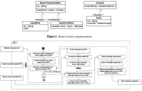
The last artifact used in our method is called a “basic transformation” (Figure 3). This is an arbitrary name that is chosen to reflect that those transfor-mations are supposed to be small and simple. Basic transformations represent black box mappings from
model concepts to code concepts. Each basic trans-formation describes a set of unique roles for inputs it can consume, where each input role has an identifier id and describes a type of model concept that can be placed in this role. Basic transformation can also have a list of input conditions attached, where each condi-tion can reject a given input. Input condicondi-tions are used to specify additional conditions on basic transforma-tion inputs that do not depend solely on the type of transformed model concepts.
however, transforming it into a method would have no sense at all.
While basic transformations support multiple input roles and thus multiple inputs, in reality they will usually work on only one input, since abstract model concepts usually get expanded into one or several code concepts when they are converted to specific
code, and not vice versa. A possibility for multiple inputs is supported “just in case”, to make recognition algorithm generic. Also, a high number of inputs would require additional input filtering (that is beyond the scope of this paper) to avoid combinatorial explo-sion of input permutations in detection algorithm.
+outputRoots : CodeConcept [0..*]
Context
+accepts( input : Input ) : Boolean
InputCondition
+id : String
+transform( context : Context )
BasicTransformation
+id : String +type
InputRole +id : String+concept : ModelConcept
Input +conditions 0..*
1
+inputs 0..*
1 +inputs 0..*
1
Figure3. Model of basic transformations
Figure 4. Recognition of basic transformation instances in a given code concept tree
To recognize a mapping from model concepts to code concepts, potentially produced by some basic transformation, we use an algorithm given in Figure 4. We test basic transformations one by one. For each basic transformation we prepare lists of inputs for every input role. We select only those model concepts that fit to a given input role by type and satisfy all input conditions if used in that role.
We sequentially make permutations of inputs in all input roles. Each permutation produces a list of inputs for a basic transformation to transform. There are no duplicate model concepts in a single permutation. There is no point in providing basic transformation with the same concept in several roles at the same time, since basic transformation can extract it several times from a single role if needed. We apply a basic transformation for each permutation thus creating one or more code concept trees with holes as a result.
For every root of a tree of code concepts produced by a basic transformation we make a list of directly equal code concepts taken from a given code concept tree that represents a given source code. Two code concepts A and B are directly equal iff:
(typeOf(A) = typeOf(B)) and (A instanceOf ConceptWithName → A.name = B.name) and
(A instanceOf ConceptWithValue → A.value = B.value)
Direct equality conditions of two code concepts ensure that those code concepts are equal as far as their types, names and values are equal, but make no assertions about equality of the contents of those code concepts. We use deep equality conditions for that. Conditions for deep equality are not commutative. Let us assume that code concept coming from a result of basic transformation function is called A and code concept coming from code concept tree that represent some source code is called B. Code concepts A and B are deeply equal if and only if they satisfy the condi-tions stated in Figure 5.
Figure 5. Direct equality conditions of code concepts
After running deep equality tests, we have a set of deeply equal matches for every root of code concept tree produced by a basic transformation. Each match is a pair of deeply equal code concepts (A, B) where A comes from result of basic transformation and B comes from a given code concept tree. Since code concept trees represent sibling statements in code in a basic transformation result, we can make unique per-mutations from subsets of matches where B's are sibling nodes in a given code concept tree and record each permutation as detection of model to code map-ping by a basic transformation at a position defined by base code concepts in matches. A basic transformation is a pattern for implementing a model element in code. Thus we can detect not only facts of implementation but also patterns of implementation of specific model elements in the given program code.
4. Example of discovering model implementa-tion patterns in source code
The method was implemented using Scala prog-ramming language [44] and tested by writing a set of sample transformations that were used to relate a sample UML model with a sample source code written in Java. We illustrate the presented method by a fol-lowing simple example that is adapted from the actual program code implementing concepts, transformations and the method being described.
Let us assume that we have model concepts that al-low partially representing a model class, as displayed in Figure 6, where function makeSlot makes a slot out of given field name, getter and setter.
class ModelClass extends ModelConcept with ConceptWithName { override var id = “ModelClass”;
var fields = List[ModelField]();
val fieldsSlot = makeSlot(name =”fields”, getter= fields _, setter=fields_= _); slots += fieldsSlot;
}
class ModelField extends ModelConcept with ConceptWithName with ConceptWithValue { override var id = “ModelField”;
}
Figure 6. Concepts for partially representing a model class
ModelClassInstance { name = “ClassA”, slots = {
Slot{
id=”fields”, values= {
ModelFieldInstance {name=”fieldA”, value=”null” } }
} } }
Figure 7. Data structure partially representing a model class
class CodeClass extends CodeConcept with ConceptWithName { override var id = “CodeClass”;
var fields = List[CodeField]();
val fieldsSlot = makeSlot(name=”fields”, getter= fields _, setter=fields_= _); slots += fieldsSlot;
}
class CodeField extends CodeConcept with ConceptWithName with ConceptWithValue { override var id = “CodeField”;
}
The structure displayed in Figure 7 describes an instance of model class concept. Also, let us assume we have code concepts that allow partially represen-ting an OOP class as displayed in Figure 8. The struc-ture displayed in Figure 9 describes an instance of code class concept.
Now let us assume we have two basic transfor-mations: one for transforming model classes into code classes and another for transforming model fields into code fields as displayed in Figure 10.
CodeClassInstance { name = “ClassA”, slots = {
Slot{
id=”fields”, values= {
CodeFieldInstance { name=”fieldA”, value=”null” } }
} } }
Figure 9. Data structure partially representing a code class
val class2Class = btf("class2Class") .from("class", classOf[ModelClass])
.hole("fields").onlyFor(BtfHoleConds.Default) .using(context => {
//get source class
val srcCls = context.input("class").asInstanceOf[ModelClass];
//create destination class val dstCls = new CodeClass(); dstCls.name = srcCls.name;
//bind hole to destination class slot "fields" context.hole("fields").bindCopyTo(dstCls.fieldsSlot);
//
context.output(dstCls); });
val field2field = btf("field2Field") .from("field", classOf[ModelField]) .using(context => {
//get source field
val srcFld = context.input("field").asInstanceOf[ModelField];
//create destination field val dstFld = new CodeField(); dstFld.name = srcFld.name; dstFld.value = srcFld.value;
//
context.output(dstFld); });
Figure 10. Example of basic transformations
Those basic transformations are defined using cus-tom builders. btf() starts building a transformation, from() adds an input role, hole() registers a hole for the later use, using() registers a transformation func-tion and returns a transformafunc-tion. We take holes from the context variable because in the implementation, the context caries a pointer to the host transformation of transformation function.
Our algorithm would work on basic transforma-tions one by one. Let us assume it starts with class2class transformation. It would scan a given model concept tree and select a ModelClassInstance because it matches a single input role of transforma-tion by type. It would then produce an input object out of the code concept Input {id = “class”, concept =
ModelConceptInstance} and pass this input to the context of the transformation. Then the transformation function would run on the given context and write back a single code concept instance that matches the CodeClassInstance and has a hole attached to the slot “fields”.
transfor-mation class2class would be registered as a detection of model to code transformation.
The same process would repeat for field2field transformation. An algorithm would scan a given mo-del concept tree and select a ModelFieldInstance be-cause it matches a single input role of transformation by type. It would then produce an input object out of ModelFieldInstance and pass it into the context of the transformation. Then the transformation function would run and write back a single code concept instance that matches the CodeFieldInstance.
Next our algorithm would scan a given code con-cept tree and would produce a single list with Code-FieldInstance in it, since CodeFieldInstance is di-rectly equal to the code concept produced by the field2field transformation. Next a deep equality che-cker would run through the list and find that CodeFieldInstance is deeply equal to the concept produced by the transformation. This pair of deeply equal code concepts together with the basic transfor-mation field2field would be registered as a detection of model to code transformation.
As a result we would know that the code concept CodeClassInstance can be produced from the model concept ModelClassInstance by applying the transfor-mation class2class and that the CodeFieldInstance can be produced from the model concept ModelFieldIns-tance by applying the transformation field2field. This tells us what implementation patterns were used by a human to produce parts of the given source code (represented by code concepts) from parts of the given program model (represented by model concepts).
5. Conclusions and future work
The method we presented can be used to detect simple model implementation patterns in source code using program concept model, code concept model, a set of basic transformation patterns for matching code concepts to model concepts, a program model and par-tially implemented code written by human. We use this technique as the part of the method for creating automatically configured program code generator that is intended for the purpose of generating program code when the software is being implemented in a do-main that is not well understood or implementation platform changes too quickly to become a stable enough target for conventional program code generation.
Our method is different from other reverse engi-neering methods. We exploit existing program model for reverse engineering and maintain the ability to use the same artifacts for detecting model implementation patterns in a source code and for composing program code generator templates.
In the future we intend to develop a method for detecting instances of more complex model-to-code transformations by combining basic transformations described in this paper.
References
[1] J. Bézivin. On the unification power of models.
Soft-ware and Systems Modeling, May 2005, Vol. 4,
No. 2, 171–188.
[2] S. Kent. Model driven engineering. Proceedings of the Third International Conference on Integrated
For-mal Methods, IFM 2002, Lect. Notes Comput. Sci.,
2002, Vol. 2335, 286–298.
[3] B. Selic. The pragmatics of model-driven develop-ment. IEEE Software, 2003, Vol. 20, No. 5, 19–25. [4] J. Herrington. Code generation in action. Manning
Publications Co, 2003.
[5] L. Ablonskis. An approach to generating program code in quickly evolving environments. In G.A. Papa-dopoulos, G.. Wojtkowski, W.W. Wojtkowski, S. Wry-cza, J. Zupancic (eds.) Information Systems Develop-ment: Towards a Service Provision Society,
Springer-Verlag: New York, 2009, 259–267.
[6] T. Skersys. Business Knowledge-Based Generation of the System Class Model. Information Technology and
Control, 2008, Vol. 37, No. 2, 145–153.
[7] O. Vasilecas, S. Sosunovas. Practical Application of BRTL Approach for Financial Reporting Domain.
Information Technology and Control, 2008, Vol. 37,
No. 2, 106–113.
[8] O. Vasilecas, D. Kalibatiene, G. Guizzardi. Towards a Formal Method for the Transformation of Ontology Axioms to Application Domain Rules. Information
Technology and Control, 2009, Vol. 38, No. 4, 271–
282.
[9] A. Armonas, L. Nemuraite. Using Attributes and Merging Algorithms for Transforming OCL Expres-sions to Code. Information Technology and Control, 2009, Vol. 38, No. 4, 283–293.
[10] R. Damaševičius, V. Štuikys. Taxonomy of the Fun-damental Concepts of Metaprogramming. Information
Technology and Control, 2008, Vol. 37, No. 2, 124–
132.
[11] OMG Unified Modeling Language (OMG UML) Superstructure, V2.1.2. OMG Available Specification formal/2007-11-02, 2007, http://www.omg.org. [12] E. J. Chikofsky, J. H. Cross II. Reverse engineering
and design recovery: A taxonomy. IEEE Software,
January 1990, Vol. 7, No. 1, 13–17.
[13] H.A. Müller, J.H. Jahnke, D.B. Smith, M.A. Storey, S.R. Tilley, K. Wong. Reverse engineering: A road-map. Proceedings of the Conference on the Future of
Software Engineering, Limerick, Ireland, 2000, 47–60.
[14] G. Canfora, M. Di Penta. New frontiers of reverse engineering. Proceedings of the 2nd Conference on
the Future of Software Engineering (FOSE’ 07), 2007,
326–341.
[15] G. Canfora, M. Di Penta. Frontiers of reverse engi-neering: A conceptual model. Proceedings of
Fron-tiers of Software Maintenance (FoSM 2008), 2008,
38–47.
[16] D. Binkley. Source Code Analysis: A Road Map.
Pro-ceedings of Future of Software Engineering, 2007,
104–119.
[17] S.R. Tilley, H.E. Muller, M.J. Whitney, K. Wong. Domain retargetable reverse enginering. Proceedings
of the 1993 International Conference on Software
[18] I. D. Baxter, C. Pidgeon, M. Mehlich. DMS: prog-ram transformations for practical scalable software evolution. Proceedings of the 26th International
Con-ference on Software Engineering (ICSE 2004), 2004,
625–634.
[19] J.R. Cordy, T.R. Dean, A.J. Malton, K.A. Schnei-der. Source Transformation in Software Engineering using the TXL Transformation System. Information
and Software Technology, 2002, Vol. 44, No. 13, 827–
837.
[20] M. Bravenboer, K.T. Kalleberg, R. Vermaas, E. Vis-ser. Stratego/XT 0.16: components for transformation systems. Proceedings of the 2006 ACM SIGPLAN Workshop on Partial Evaluation and Semantics-based
Program Manipulation, January 9-10, 2006, 95–99.
[21] S. Ducasse, M. Lanza, S. Tichelaar. Moose: an ex-tensible language-independent environment for reengi-neering object-oriented systems. In Proceedings of the Second International Symposium on Constructing
Software Engineering Tools (CoSET 2000), 2000.
[22] R. Ferenc, A. Beszedes, M. Tarkiainen, T. Gyimo-thy. Columbus – reverse engineering tool and schema for C++. Proceedings of the International Conference
on Software Maintenance (ICSM'02), 2002, 172–181.
[23] B. Paradauskas, A. Laurikaitis. Business knowledge extraxtion using program understanding and data ana-lysis techniques. Proceedings of the 15th International Conference on Information and Software
Techno-logies, IT 2009, Kaunas, Lithuania, April 23-24, 2009,
337–354.
[24] A. Sutton, J.I. Maletic. Mappings for accurately re-verse engineering UML class models from C++.
Pro-ceedings of the 12th Working Conference on Reverse
Engineering, 2005, 175–184.
[25] T. Systa. Static and Dynamic Reverse Engineering Techniques for Java Software Systems. Academic
Dis-sertation, University of Tampere, 2000.
[26] U.A. Nickel, J. Niere, J.P. Wadsack, A. Zundorf. Roundtrip Engineering with FUJABA. Proceedings of
the 2nd Workshop on Software-Reengineering (WSR),
August, 2000.
[27] M. Bork, L. Geiger, C. Schneider, A. Zundorf. To-wards Roundtrip Engineering – a Template-Based Re-verse Engineering Approach. In Model Driven Archi-tecture: Foundations and Applications, Lect. Notes
Comput. Sci., 2008, Vol. 5095, 33–47.
[28] C. Rich, L.M. Wills. Recognizing a program's design: a graph-parsing approach. IEEE Software, 1990, Vol. 7, No. 1, 82–89.
[29] D.C. Brotsky. An Algorithm for Parsing Flow Graphs.
Technical report TR-704, MIT Artificial Intelligence
Laboratory, March, 1984.
[30] E. Gamma, R. Helm, R. Johnson, J.M. Vlissides. Design Patterns – Elements of Reusable Object-Orien-ted Software. Addison-Wesley Publishing Co., 1995.
[31] D. Heuzeroth, T. Holl, G. Högström, W. Löwe. Automatic design pattern detection. Proceedings of the
11th IEEE International Workshop on Program
Com-prehension, 2003, 94–103.
[32] N. Shi, R.A. Olsson. Reverse Engineering of Design Patterns from Java Source Code. Proceedings of the
21st IEEE/ACM International Conference on
Auto-mated Software Engineering, 2006, 123–134.
[33] N. Tsantalis, A. Chatzigeorgiou, G. Stephanides, S.T. Halkidis. Design pattern detection using similari-ty scoring. IEEE Transactions on Software Eng, 2006,
Vol. 32, No. 1, 896–909.
[34] V.D. Blondel, A. Gajardo, M. Heymans, P. Senel-lart, P.V. Dooren. A measure of similarity between graph vertices: applications to synonym extraction and web searching. SIAM Review, 2004, Vol. 46, No. 4, 647–666.
[35] Y. G. Gueheneuc, H. Sahraoui, F. Zaidi. Fingerprin-ting design patterns. Proceedings of the 11th Working
Conference on Reverse Engineering (WCRE’04),
2004, 172–181.
[36] R. Ferenc, A. Beszedes, L. Fulop, J. Lele. Design pattern mining enhanced by machine learning.
Procee-dings of the 21st IEEE International Conference on
Software Maintenance, 2005, 295–304.
[37] P. Tonella, G. Antoniol. Object Oriented Design Pat-tern Inference. Proceedings of the IEEE International
Conference on Software Maintenance, 1999, 230–238.
[38] A. Laukaitis, O. Vasilecas, D. Plikynas. Formal Con-cept Analysis for Business Information Systems.
Information Technology and Control, 2008, Vol. 37,
No. 1, 33–37.
[39] J.M. Smith, D. Stotts. Elemental design patterns: A logical inference system and theorem prover support for flexible discovery of design patterns. Technical
Report TR02-038, Departament of Computer Science,
University of North Carolina, 2002.
[40] J. Fabry, T. Mens. Language independent detection of object-oriented design patterns. Computer Languages,
Systems & Structures, 2004, Vol. 30, No. 1-2, 21–33.
[41] H. Albin-Amiot, P. Cointe, Y. G. Guéhéneuc, N. Jus-sien. Instantiating and detecting design patterns: put-ting bits and pieces together. Proceedings of the 16th Annual International Conference on Automated
Soft-ware Engineering (ASE’01), 2001, 166–173.
[42] Z. Balanyi, R. Ferenc. Mining design patterns from C++ source code. In Proceedings of the International
Conference on Software Maintenance, 2003, 305–314.
[43] J. M. Smith, D. Stotts. SPQR: Flexible automated design pattern extraction from source code.
Procee-dings of the 18th IEEE International Conference on
Automated Software Engineering, 2003, 215–224.
[44] D. Wampler, A. Payne. Programming Scala. O'Reilly
Media, 2009.