A New Steganographic Algorithm
Based on Multi Directional PVD
and Modified LSB
ITC 1/46
Journal of Information Technology and Control
Vol. 46 / No. 1 / 2017 pp. 16-36
DOI 10.5755/j01.itc.46.1.15253 © Kaunas University of Technology
A New Steganographic Algorithm Based on Multi Directional PVD and Modified LSB
Received 2016/10/16 Accepted after revision 2016/02/17 http://dx.doi.org/10.5755/j01.itc.46.1.15253
Corresponding author: [email protected]
Khalid A. Darabkh, Ahlam K. Al-Dhamari, and Iyad F. Jafar
Department of Computer Engineering; The University of Jordan; Amman, 11942, Jordan; phone: +962-796969219; fax: +962-65300813; emails: [email protected], [email protected], and [email protected]
Steganographic techniques can be utilized to conceal data within digital images with small or invisible changes in the perceived appearance of the image. Generally, five main objectives are used to assess the performance of steganographic algorithms which include embedding capacity, imperceptibility, security, robustness and complexity. However, steganographic algorithms hardly take all of these factors into account. In this paper, a novel steganographic algorithm for digital images is proposed based on the pixel-value differencing (PVD) and modified least-significant bit (LSB) substitution (MDPVD-MLSB) techniques to address most of aforemen-tioned objectives. Although there are many techniques for concealing data within pixels, the restricting factor is always the amount of bits adjusted in every pixel. Therefore, the main contributions of this paper aim to achieve a balance between the amount of embedded data, the level of acceptable distortion, as well as providing high level of security. The performance of this algorithm has been extensively evaluated in terms of embedding capacity, peak signal-to-noise ratio (PSNR) and structural similarity index measure (SSIM). Simulation results and comparisons with six relevant algorithms are presented to demonstrate the effectiveness of this proposed algorithm.
KEYWORDS:Tri-way pixel-value differencing (TPVD), Octa pixel-value differencing (Octa-PVD), least-sig-nificant bit (LSB), optimal pixel adjustment process (OPAP), embedding capacity, imperceptibility.
Introduction
Internet has become a vital part of everyone’s lives,
17 Information Technology and Control 2017/1/46
wired Ethernet cables keeping in mind that wireless networks have numerous obstacles, among them low bandwidth, insecure links, and high error rate [1-9]. One of the primary issues of sending data over the Internet is security [10-11]. The ability to communi-cate securely is an important concern to organiza-tions, people, and government. Therefore, it becomes very crucial to take data security into consideration as one of the most fundamental factors that requires attention during data transmission process. Gener-ally, there are two popular approaches to secure data [12]. The first one is encryption, in which the origi-nal text is transformed into a cipher-text via certain algorithms. Thus, encryption changes the text into unreadable and incomprehensible text, which makes it suspicious enough to attract attackers’ attention. Data Encryption Standard (DES), Advanced Encryp-tion Standard (AES) and Rivest-Shamir-Adleman cryptosystem (RSA) are some of the common encryp-tion methods [13]. The other approach is data hiding which is basically classified into two parts, namely, watermarking and steganography [14-17]. The main difference between them is that the former secures the carrier-object along with copyright information, while the later secures the embedded message into the carrier-object only [18-24]. Interestingly, there are other differences between the two methods based on the required performance objectives. For instance, watermarking is more sensitive to robustness than steganography. On the other hand, the steganogra-phy is more sensitive to capacity than watermarking. The security in watermarking lies in the difficulty of removing the watermark while in steganography, it lies in the difficulty of detecting/extracting the em-bedded data. Additionally, watermarking techniques are made between a sender and numerous receivers, whereas steganographic techniques are made be-tween a sender and only one receiver [14].
This paper proposes an efficient and robust dynamic data hiding algorithm which mainly aims to improve the embedding capacity of the secret data, enhance the visual quality of stego-image, and make steganalysis a very hard task. The proposed algorithm is based on multi-directional pixel-value differencing (MDPVD) and modified least-significant bit (MLSB). However, the rest of the paper is organized as follows. In Sec-tion 2, a literature review of the most related works in the field is presented. Section 3 details the proposed algorithm. Experimental results and discussions are
provided in Section 4. Section 5 concludes the work and provides future possible directions.
Related work
Image steganographic algorithms, which have been discussed in literature, can be classified based on the embedding domain into two main classes: spatial do-main and transform dodo-main [14, 25-27]. The spatial domain algorithms are most frequently used because of their good concealment, great capability to hide information, and ease of realization [28]. In spatial domain methods, a steganographer modifies the pixel values of the host image directly [12]. LSB and PVD are the most common algorithms that essentially be-long to this class [29-30]. In the transform domain algorithms, a steganographer embeds information into the coefficients of some transformed version of the host image [31]. The cover image can be converted into its transform domain by using one of the wavelet transformations such as: Discrete Cosine Transform (DCT), Discrete Wavelet Transform (DWT), and Fast Fourier Transform (FFT). Data insertion performed in the transform domain is greatly used for robust watermarking [25]. JSteg, F3, F4, F5, and Outguess methods are known steganographic algorithms that operate in the transform domain [25, 32].
of modern algorithms for secret data hiding is PVD, which can provide high embedding capacity and ex-tremely good stego-image visual quality. For instance, the PVD method can achieve the capacity of 50,960 bytes (1.555 bpp) for Lena test image and its stego-im-age has a PSNR of 41.79 dB [34]. The main idea behind PVD is to use the difference between two consecutive pixels of a gray scale image to hide data. In [40], pix-el-value differencing is used to distinguish between edge areas and smooth areas. Consequently, the capac-ity of embedded data in edge areas is higher than that of smooth areas. Wu and Tsai [40] proposed two types of quantization range table based on the range width of the power of two. The first range has the widths of {2, 2, 4, 4, 4, 8, 8, 32, 32, 64, 64} and is used to provide high imperceptibility or higher values of PSNR. The sec-ond range has the widths of {8, 8, 16, 32, 64, 128} and is used to provide high embedding capacity. It is worth mentioning that there are rare studies that aim to de-sign new range tables. Tseng and Leng [41] proposed a PVD-based algorithm that mainly includes a new quantization range table based on the perfect square number, in order to obtain the secret data bits by using the difference value between consecutive pixels. They partition each range into two subranges for embedding variable number of secret data bits. After determining the perfect square number which belongs to the in-terval [1, 16], the ranges produced by this method are as follows {[0,1], [2,5], [6,11], [12,19], [20,29], [30,41], [42,55], [56,71], [72,89], [90,109], [110,131], [132,155], [156,181], [182,209], [210,239], [240,255]}.
In spite of PVD simplicity (i.e., being efficient in achieving large embedding capacity and extremely good stego-image visual quality) it has a limitation with respect to the capacity. In particular, the PVD does not make full use of edge areas. Motivated by the original PVD in [40], Chang et al [30] proposed a PVD-based scheme called tri-way pixel-value differ-encing (TPVD), which uses three different directional edges instead of one directional edge to eliminate the capacity limitation of the PVD method. Furthermore, the authors used the reference point selection and adaptive conditions in order to improve the quality of the stego- image. Based on TPVD, a data hiding algo-rithm was proposed in [42] in which three-direction-al PVD method for gray images is used. Unlike PVD and TPVD, the position of base pixel in this method is variable and depends on the pixel value of each group. Based on an index function, Jung and Yoo [43]
pro-posed a high-capacity steganographic approach. In this method, the cover-image is partitioned into B × B
sub-blocks and the base pixel is computed according to the index function. Rather than fixing the position of the base pixel, the position in this method depends on an index. The indexes must satisfy the condition:
1 ,
0≤x y≤B− . After applying the index function to select the base pixel, the pixel values are sorted in as-cending/descending order according to the results of the index function. Exploiting Modification Direction (EMD) method is devised in [44]. The importance of the EMD scheme lies in providing a good quality of stego-image with PSNR of more than 52 dB, since at most only one cover pixel in each pixel group needs to be incremented or decremented by one. Taking into account the EMD method, Shen and Huang [45] pro-posed a new scheme to enhance the embedding ca-pacity and hide digits in any-ary notation adaptively by using the absolute difference value of pixel pairs. Similar to TPVD, Thaneker and Pawar [46] proposed a new PVD scheme with eight directional edges, which is called Octa-PVD, to achieve a better capacity than that in PVD and TPVD. Unfortunately, it is noticed that even though this research used more direction-al edges, the image distortion increases dramaticdirection-ally. Therefore, the big challenge in PVD-based stegano-graphic schemes, which have multi directional edges, is to achieve a balance between the amount of both the embedded data and the acceptable distortion, as well as provide high level of security.
In summary, an efficient and robust dynamic algo-rithm of data hiding is proposed in this paper. This algorithm aims to improve the embedding capac-ity of the secret data, enhance the visual qualcapac-ity of stego-image, and make steganalysis a very hard task. The proposed algorithm is based on multi-direction-al PVD and modified LSB. The idea of MLSB is to in-crease or dein-crease the pixel gray value after embed-ding, using simple LSB replacement by 2k (where k is
the number of secret data bits that have to be embedded in LSBs of each pixel in a cover image) in order to en-hance the image quality [29, 42].
The proposed algorithm
19 Information Technology and Control 2017/1/46
are called (Quinary-PVD-MLSB) and (Octa-PVD-MLSB) because the cover-image is partitioned either into 2 × 3 pixel blocks, each of which has 5 pairs to embed secret data, or into 3 × 3 pixel blocks, each of which has 8 pairs to embed secret data. On the other hand, three branch conditions are proposed that per-mit automatic switching between MDPVD and MLSB (one of them can be selected only in the embedding and extracting procedures). In fact, these branch con-ditions can certainly reduce distortion caused by the offsetting of pairs process. If the selected branch con-dition is satisfied, then the current block can raise the distortion. Thus, this block must be embedded using MLSB to avoid any degradation in the visual quality of stego-image. The details about the proposed branch conditions are described in Section 3.1.
To protect the embedded secret data when using MLSB embedding, a secret key (SK) is used to insert secret data bits in different pixel indices according to the generated integer set Ns. Nsis generated using the set-generation function Hs (SK, Nbp), where Nbp is the number of block pixels, Ns = {Nsi | i = 1, 2… Nbp} and
3
than 52 dB, since at most only one cover pixel in each pixel group needs to be incremented or decremented by one. Taking into account the EMD method, Shen and Huang [45] proposed a new scheme to enhance the embedding capacity and hide digits in any-ary notation adaptively by using the absolute difference value of pixel pairs. Similar to TPVD, Thaneker and Pawar [46] proposed a new PVD scheme with eight directional edges, which is called Octa-PVD, to achieve a better capacity than that in PVD and TPVD. Unfortunately, it is noticed that even though this research used more directional edges, the image distortion increases dramatically. Therefore, the big challenge in PVD-based steganographic schemes, which have multi directional edges, is to achieve a balance between the amount of both the embedded data and the acceptable distortion, as well as provide high level of security.
In summary, an efficient and robust dynamic algorithm of data hiding is proposed in this paper. This algorithm aims to improve the embedding capacity of the secret data, enhance the visual quality of stego-image, and make steganalysis a very hard task. The proposed algorithm is based on multi-directional PVD and modified LSB. The idea of MLSB is to increase or decrease the pixel gray value after embedding, using simple LSB replacement by 2k (where k is the number of secret data bits that have to be embedded in LSBs of each
pixel in a cover image) in order to enhance the image quality [29, 42]. 3. The proposed algorithm
]! ,1 [ Nbp
SK (i.e. SK[1,720]in Quinary-PVD-MLSB andSK [1,362880 ] in Octa-PVD-MLSB). In other words, based on Nbp, Hs set function will generate (Nbp!)possible permutations and according to the selected SK value, Hs will generate the required Ns. Each element in the Ns set is unique and its value falls within the range [1, Nbp].
Generally, the proposed algorithm has three main phases: the partition phase, the embedding phase, and the extracting phase, which will be described in details in Sections 3.2, 3.3 and 3.4, respectively.
3.1. Branch conditions to reduce distortion
Although both Quinary-PVD and Octa-PVD can hide large amount of secret data if they are utilized without using MLSB, embedding such large amount of data can clearly cause a very poor visual quality due to the offsetting of pairs process. Therefore, there is a need to determine some branch conditions that allow automatic switching between Quinary-PVD and MLSB or between Octa-PVD and MLSB. Three branch conditions are designed and only one of them can be used at a time according to the requirements of the practical applications such as the embedding capacity and the visual quality of the stego-image. These conditions are called BC1,
BC2 and BC3. Theyare as the following:
1) At least one of the difference valuesis equal or greater than 8 (i.e.D8). 2) At least one of the difference values is equal or greater than 16 (i.e.D16). 3) At least one of the difference values is equal or greater than 32 (i.e.D32).
(i.e.
3
than 52 dB, since at most only one cover pixel in each pixel group needs to be incremented or decremented by one. Taking into account the EMD method, Shen and Huang [45] proposed a new scheme to enhance the embedding capacity and hide digits in any-ary notation adaptively by using the absolute difference value of pixel pairs. Similar to TPVD, Thaneker and Pawar [46] proposed a new PVD scheme with eight directional edges, which is called Octa-PVD, to achieve a better capacity than that in PVD and TPVD. Unfortunately, it is noticed that even though this research used more directional edges, the image distortion increases dramatically. Therefore, the big challenge in PVD-based steganographic schemes, which have multi directional edges, is to achieve a balance between the amount of both the embedded data and the acceptable distortion, as well as provide high level of security.
In summary, an efficient and robust dynamic algorithm of data hiding is proposed in this paper. This algorithm aims to improve the embedding capacity of the secret data, enhance the visual quality of stego-image, and make steganalysis a very hard task. The proposed algorithm is based on multi-directional PVD and modified LSB. The idea of MLSB is to increase or decrease the pixel gray value after embedding, using simple LSB replacement by 2k (where k is the number of secret data bits that have to be embedded in LSBs of each
pixel in a cover image) in order to enhance the image quality [29, 42]. 3. The proposed algorithm
]! ,1 [ Nbp
SK (i.e. SK[1,720]in Quinary-PVD-MLSB andSK [1,362880 ] in Octa-PVD-MLSB). In other words, based on Nbp, Hs set function will generate (Nbp!)possible permutations and according to the selected SK value, Hs will generate the required Ns. Each element in the Ns set is unique and its value falls within the range [1, Nbp].
Generally, the proposed algorithm has three main phases: the partition phase, the embedding phase, and the extracting phase, which will be described in details in Sections 3.2, 3.3 and 3.4, respectively.
3.1. Branch conditions to reduce distortion
Although both Quinary-PVD and Octa-PVD can hide large amount of secret data if they are utilized without using MLSB, embedding such large amount of data can clearly cause a very poor visual quality due to the offsetting of pairs process. Therefore, there is a need to determine some branch conditions that allow automatic switching between Quinary-PVD and MLSB or between Octa-PVD and MLSB. Three branch conditions are designed and only one of them can be used at a time according to the requirements of the practical applications such as the embedding capacity and the visual quality of the stego-image. These conditions are called BC1,
BC2 and BC3. Theyare as the following:
1) At least one of the difference valuesis equal or greater than 8 (i.e.D8). 2) At least one of the difference values is equal or greater than 16 (i.e.D16). 3) At least one of the difference values is equal or greater than 32 (i.e.D32).
in Quinary-PVD-MLSB and SK
∈
[1,362880] in Octa-PVD-MLSB). In oth-er words, based on Nbp, Hs set function will generate3
than 52 dB, since at most only one cover pixel in each pixel group needs to be incremented or decremented by one. Taking into account the EMD method, Shen and Huang [45] proposed a new scheme to enhance the embedding capacity and hide digits in any-ary notation adaptively by using the absolute difference value of pixel pairs. Similar to TPVD, Thaneker and Pawar [46] proposed a new PVD scheme with eight directional edges, which is called Octa-PVD, to achieve a better capacity than that in PVD and TPVD. Unfortunately, it is noticed that even though this research used more directional edges, the image distortion increases dramatically. Therefore, the big challenge in PVD-based steganographic schemes, which have multi directional edges, is to achieve a balance between the amount of both the embedded data and the acceptable distortion, as well as provide high level of security.
In summary, an efficient and robust dynamic algorithm of data hiding is proposed in this paper. This algorithm aims to improve the embedding capacity of the secret data, enhance the visual quality of stego-image, and make steganalysis a very hard task. The proposed algorithm is based on multi-directional PVD and modified LSB. The idea of MLSB is to increase or decrease the pixel gray value after embedding, using simple LSB replacement by 2k (where k is the number of secret data bits that have to be embedded in LSBs of each pixel in a cover image) in order to enhance the image quality [29, 42].
3. The proposed algorithm
]! ,1 [ Nbp
SK (i.e. SK[1,720]in Quinary-PVD-MLSB andSK [1,362880 ] in Octa-PVD-MLSB). In other words, based on Nbp, Hs set function will generate (Nbp!)possible permutations and according to the selected SK value, Hs will generate the required Ns. Each element in the Ns set is unique and its value falls within the
range [1, Nbp].
Generally, the proposed algorithm has three main phases: the partition phase, the embedding phase, and the extracting phase, which will be described in details in Sections 3.2, 3.3 and 3.4, respectively.
3.1. Branch conditions to reduce distortion
Although both Quinary-PVD and Octa-PVD can hide large amount of secret data if they are utilized without using MLSB, embedding such large amount of data can clearly cause a very poor visual quality due to the offsetting of pairs process. Therefore, there is a need to determine some branch conditions that allow automatic switching between Quinary-PVD and MLSB or between Octa-PVD and MLSB. Three branch conditions are designed and only one of them can be used at a time according to the requirements of the practical applications such as the embedding capacity and the visual quality of the stego-image. These conditions are called BC1, BC2 and BC3. They are as the following:
1) At least one of the difference valuesis equal or greater than 8 (i.e.D8). 2) At least one of the difference values is equal or greater than 16 (i.e.D16). 3) At least one of the difference values is equal or greater than 32 (i.e.D32).
possible permutations and according to the se-lected SK value, Hs will generate the required Ns. Each element in the Ns set is unique and its value falls with-in the range [1, Nbp].
Generally, the proposed algorithm has three main phases: the partition phase, the embedding phase, and the extracting phase, which will be described in details in Sections 3.2, 3.3 and 3.4, respectively. Branch conditions to reduce distortion
Although both Quinary-PVD and Octa-PVD can hide large amount of secret data if they are utilized without using MLSB, embedding such large amount of data can clearly cause a very poor visual quality due to the offsetting of pairs process. Therefore, there is a need to determine some branch conditions that allow auto-matic switching between Quinary-PVD and MLSB or between Octa-PVD and MLSB. Three branch condi-tions are designed and only one of them can be used at a time according to the requirements of the practical applications such as the embedding capacity and the visual quality of the stego-image. These conditions are called BC1, BC2 and BC3. Theyare as the following:
1 At least one of the difference values is equal or greater than 8 (i.e.
3
than 52 dB, since at most only one cover pixel in each pixel group needs to be incremented or decremented by one. Taking into account the EMD method, Shen and Huang [45] proposed a new scheme to enhance the embedding capacity and hide digits in any-ary notation adaptively by using the absolute difference value of pixel pairs. Similar to TPVD, Thaneker and Pawar [46] proposed a new PVD scheme with eight directional edges, which is called Octa-PVD, to achieve a better capacity than that in PVD and TPVD. Unfortunately, it is noticed that even though this research used more directional edges, the image distortion increases dramatically. Therefore, the big challenge in PVD-based steganographic schemes, which have multi directional edges, is to achieve a balance between the amount of both the embedded data and the acceptable distortion, as well as provide high level of security.
In summary, an efficient and robust dynamic algorithm of data hiding is proposed in this paper. This algorithm aims to improve the embedding capacity of the secret data, enhance the visual quality of stego-image, and make steganalysis a very hard task. The proposed algorithm is based on multi-directional PVD and modified LSB. The idea of MLSB is to increase or decrease the pixel gray value after embedding, using simple LSB replacement by 2k (where k is the number of secret data bits that have to be embedded in LSBs of each
pixel in a cover image) in order to enhance the image quality [29, 42]. 3. The proposed algorithm
Since this study is based on MDPVD, the algorithm is divided into two separate schemes. These schemes are called (Quinary-PVD-MLSB) and (Octa-PVD-MLSB) because the cover-image is partitioned either into 2 × 3 pixel blocks, each of which has 5 pairs to embed secret data, or into 3 × 3 pixel blocks, each of which has 8 pairs to embed secret data. On the other hand, three branch conditions are proposed that permit automatic switching between MDPVD and MLSB (one of them can be selected only in the embedding and extracting procedures). In fact, these branch conditions can certainly reduce distortion caused by the offsetting of pairs process. If the selected branch condition is satisfied, then the current block can raise the distortion. Thus, this block must be embedded using MLSB to avoid any degradation in the visual quality of stego-image. The details about the proposed branch conditions are described in Section 3.1.
To protect the embedded secret data when using MLSB embedding, a secret key (SK) is used to insert secret data bits in different pixel indices according to the generated integer set Ns. Nsis generated using the set-generation function Hs (SK, Nbp), where Nbp is the number of block pixels, Ns = {Nsi | i = 1, 2… Nbp} and
]! ,1 [ Nbp
SK (i.e. SK[1,720]in Quinary-PVD-MLSB andSK [1,362880 ] in Octa-PVD-MLSB). In other words, based on Nbp, Hs set function will generate (Nbp!)possible permutations and according to the selected SK value, Hs will generate the required Ns. Each element in the Ns set is unique and its value falls within the range [1, Nbp].
Generally, the proposed algorithm has three main phases: the partition phase, the embedding phase, and the extracting phase, which will be described in details in Sections 3.2, 3.3 and 3.4, respectively.
3.1. Branch conditions to reduce distortion
Although both Quinary-PVD and Octa-PVD can hide large amount of secret data if they are utilized without using MLSB, embedding such large amount of data can clearly cause a very poor visual quality due to the offsetting of pairs process. Therefore, there is a need to determine some branch conditions that allow automatic switching between Quinary-PVD and MLSB or between Octa-PVD and MLSB. Three branch conditions are designed and only one of them can be used at a time according to the requirements of the practical applications such as the embedding capacity and the visual quality of the stego-image. These conditions are called BC1,
BC2 and BC3. Theyare as the following:
1) At least one of the difference valuesis equal or greater than 8 (i.e.D8). 2) At least one of the difference values is equal or greater than 16 (i.e.D16). 3) At least one of the difference values is equal or greater than 32 (i.e.D32).
).
2 At least one of the difference values is equal or greater than 16 (i.e.
3
than 52 dB, since at most only one cover pixel in each pixel group needs to be incremented or decremented by one. Taking into account the EMD method, Shen and Huang [45] proposed a new scheme to enhance the embedding capacity and hide digits in any-ary notation adaptively by using the absolute difference value of pixel pairs. Similar to TPVD, Thaneker and Pawar [46] proposed a new PVD scheme with eight directional edges, which is called Octa-PVD, to achieve a better capacity than that in PVD and TPVD. Unfortunately, it is noticed that even though this research used more directional edges, the image distortion increases dramatically. Therefore, the big challenge in PVD-based steganographic schemes, which have multi directional edges, is to achieve a balance between the amount of both the embedded data and the acceptable distortion, as well as provide high level of security.
In summary, an efficient and robust dynamic algorithm of data hiding is proposed in this paper. This algorithm aims to improve the embedding capacity of the secret data, enhance the visual quality of stego-image, and make steganalysis a very hard task. The proposed algorithm is based on multi-directional PVD and modified LSB. The idea of MLSB is to increase or decrease the pixel gray value after embedding, using simple LSB replacement by 2k (where k is the number of secret data bits that have to be embedded in LSBs of each
pixel in a cover image) in order to enhance the image quality [29, 42]. 3. The proposed algorithm
Since this study is based on MDPVD, the algorithm is divided into two separate schemes. These schemes are called (Quinary-PVD-MLSB) and (Octa-PVD-MLSB) because the cover-image is partitioned either into 2 × 3 pixel blocks, each of which has 5 pairs to embed secret data, or into 3 × 3 pixel blocks, each of which has 8 pairs to embed secret data. On the other hand, three branch conditions are proposed that permit automatic switching between MDPVD and MLSB (one of them can be selected only in the embedding and extracting procedures). In fact, these branch conditions can certainly reduce distortion caused by the offsetting of pairs process. If the selected branch condition is satisfied, then the current block can raise the distortion. Thus, this block must be embedded using MLSB to avoid any degradation in the visual quality of stego-image. The details about the proposed branch conditions are described in Section 3.1.
To protect the embedded secret data when using MLSB embedding, a secret key (SK) is used to insert secret data bits in different pixel indices according to the generated integer set Ns. Ns is generated using the set-generation function Hs (SK, Nbp), where Nbp is the number of block pixels, Ns = {Nsi | i = 1, 2… Nbp} and
]! ,1 [ Nbp
SK (i.e. SK[1,720]in Quinary-PVD-MLSB andSK [1,362880 ] in Octa-PVD-MLSB). In other words, based on Nbp, Hs set function will generate (Nbp!)possible permutations and according to the selected SK value, Hs will generate the required Ns. Each element in the Ns set is unique and its value falls within the range [1, Nbp].
Generally, the proposed algorithm has three main phases: the partition phase, the embedding phase, and the extracting phase, which will be described in details in Sections 3.2, 3.3 and 3.4, respectively.
3.1. Branch conditions to reduce distortion
Although both Quinary-PVD and Octa-PVD can hide large amount of secret data if they are utilized without using MLSB, embedding such large amount of data can clearly cause a very poor visual quality due to the offsetting of pairs process. Therefore, there is a need to determine some branch conditions that allow automatic switching between Quinary-PVD and MLSB or between Octa-PVD and MLSB. Three branch conditions are designed and only one of them can be used at a time according to the requirements of the practical applications such as the embedding capacity and the visual quality of the stego-image. These conditions are called BC1,
BC2 and BC3. Theyare as the following:
1) At least one of the difference valuesis equal or greater than 8 (i.e.D8). 2) At least one of the difference values is equal or greater than 16 (i.e.D16). 3) At least one of the difference values is equal or greater than 32 (i.e.D32). ).
3 At least one of the difference values is equal or greater than 32 (i.e.
3
than 52 dB, since at most only one cover pixel in each pixel group needs to be incremented or decremented by one. Taking into account the EMD method, Shen and Huang [45] proposed a new scheme to enhance the embedding capacity and hide digits in any-ary notation adaptively by using the absolute difference value of pixel pairs. Similar to TPVD, Thaneker and Pawar [46] proposed a new PVD scheme with eight directional edges, which is called Octa-PVD, to achieve a better capacity than that in PVD and TPVD. Unfortunately, it is noticed that even though this research used more directional edges, the image distortion increases dramatically. Therefore, the big challenge in PVD-based steganographic schemes, which have multi directional edges, is to achieve a balance between the amount of both the embedded data and the acceptable distortion, as well as provide high level of security.
In summary, an efficient and robust dynamic algorithm of data hiding is proposed in this paper. This algorithm aims to improve the embedding capacity of the secret data, enhance the visual quality of stego-image, and make steganalysis a very hard task. The proposed algorithm is based on multi-directional PVD and modified LSB. The idea of MLSB is to increase or decrease the pixel gray value after embedding, using simple LSB replacement by 2k (where k is the number of secret data bits that have to be embedded in LSBs of each
pixel in a cover image) in order to enhance the image quality [29, 42]. 3. The proposed algorithm
Since this study is based on MDPVD, the algorithm is divided into two separate schemes. These schemes are called (Quinary-PVD-MLSB) and (Octa-PVD-MLSB) because the cover-image is partitioned either into 2 × 3 pixel blocks, each of which has 5 pairs to embed secret data, or into 3 × 3 pixel blocks, each of which has 8 pairs to embed secret data. On the other hand, three branch conditions are proposed that permit automatic switching between MDPVD and MLSB (one of them can be selected only in the embedding and extracting procedures). In fact, these branch conditions can certainly reduce distortion caused by the offsetting of pairs process. If the selected branch condition is satisfied, then the current block can raise the distortion. Thus, this block must be embedded using MLSB to avoid any degradation in the visual quality of stego-image. The details about the proposed branch conditions are described in Section 3.1.
To protect the embedded secret data when using MLSB embedding, a secret key (SK) is used to insert secret data bits in different pixel indices according to the generated integer set Ns. Nsis generated using the set-generation function Hs (SK, Nbp), where Nbp is the number of block pixels, Ns = {Nsi | i = 1, 2… Nbp} and
]! ,1 [ Nbp
SK (i.e. SK[1,720]in Quinary-PVD-MLSB andSK [1,362880 ] in Octa-PVD-MLSB). In other words, based on Nbp, Hs set function will generate (Nbp!)possible permutations and according to the selected SK value, Hs will generate the required Ns. Each element in the Ns set is unique and its value falls within the range [1, Nbp].
Generally, the proposed algorithm has three main phases: the partition phase, the embedding phase, and the extracting phase, which will be described in details in Sections 3.2, 3.3 and 3.4, respectively.
3.1. Branch conditions to reduce distortion
Although both Quinary-PVD and Octa-PVD can hide large amount of secret data if they are utilized without using MLSB, embedding such large amount of data can clearly cause a very poor visual quality due to the offsetting of pairs process. Therefore, there is a need to determine some branch conditions that allow automatic switching between Quinary-PVD and MLSB or between Octa-PVD and MLSB. Three branch conditions are designed and only one of them can be used at a time according to the requirements of the practical applications such as the embedding capacity and the visual quality of the stego-image. These conditions are called BC1,
BC2 and BC3. Theyare as the following:
1) At least one of the difference valuesis equal or greater than 8 (i.e.D8). 2) At least one of the difference values is equal or greater than 16 (i.e.D16). 3) At least one of the difference values is equal or greater than 32 (i.e.D32).).
Where D {d |i 0,..., N= i = bp−2}. If the selected branch condition from the above three conditions is satisfied, the current block results in higher distortion if MDP-VD is used. Therefore, MLSB is used to individually embed each pixel in the block.
Partition phase
In the proposed algorithm, the cover-image (CI) is partitioned into 2×3 or 3×3 non-overlapping pixel blocks Bi, each of which has six or nine pixels in raster scan order or zig-zag scan order such that:
Bii| 1,2,...,M6N
CI Or | ,12,..., .
9
Bii M N
CI (1)
Fig. 1 (a, b) shows the block structures for the two schemes of the proposed algorithm.
Figure 1
(a, b). Block structures in MDPVD-MLSB algorithm
(a) Block structure for the Quinary-PVD-MLSB scheme.
p(x,y) p(x,y+1) p(x,y+2) p(x+1,y) p(x+1,y+1) p(x+1,y+2)
(a) Block structure for the Quinary-PVD-MLSB scheme.
p(x,y) p(x,y+1) p(x,y+2) p(x+1,y) p(x+1,y+1) p(x+1,y+2) p(x+2,y) p(x+2,y+1) P(x+2,y+2)
(b) Block structure for the Octa-PVD-MLSB scheme. p(x,y) p(x,y+1) p(x,y+2)
p(x+1,y) p(x+1,y+1) p(x+1,y+2)
(a) Block structure for the Quinary-PVD-MLSB scheme.
p(x,y) p(x,y+1) p(x,y+2) p(x+1,y) p(x+1,y+1) p(x+1,y+2) p(x+2,y) p(x+2,y+1) P(x+2,y+2)
(b) Block structure for the Octa-PVD-MLSB scheme.
(b) Block structure for the Octa-PVD-MLSB scheme.
p(x,y) p(x,y+1) p(x,y+2) p(x+1,y) p(x+1,y+1) p(x+1,y+2)
(a) Block structure for the Quinary-PVD-MLSB scheme.
p(x,y) p(x,y+1) p(x,y+2) p(x+1,y) p(x+1,y+1) p(x+1,y+2) p(x+2,y) p(x+2,y+1) P(x+2,y+2)
(b) Block structure for the Octa-PVD-MLSB scheme. p(x,y) p(x,y+1) p(x,y+2)
p(x+1,y) p(x+1,y+1) p(x+1,y+2)
(a) Block structure for the Quinary-PVD-MLSB scheme.
p(x,y) p(x,y+1) p(x,y+2) p(x+1,y) p(x+1,y+1) p(x+1,y+2) p(x+2,y) p(x+2,y+1) P(x+2,y+2)
Embedding phase
The embedding phase of our algorithm when the Octa-PVD-MLSB scheme is considered will be ex-plained. As shown in Fig. 1. (b), each 3×3 block in-cludes nine pixels { p(x, y),p(x, y+1), p(x, y+2), p(x+1, y), p(x+1, y+1), p(x+1, y+2), p(x+2,y), p(x+2, y+1), p(x+2, y+2)} where x and y are the pixel location in the cover image. Let
p
(x+1,y+1)be the beginning point, then eight pixel pairs can be formed by pairing the beginning pointp
(x+1,y+1)with each of its eight neighbors in the block. These eight pixel pairs are denoted by{P0,P1,P2,P3,P4,P5,P6,P7}. When using Octa-PVD to embed secret data bits, each pair has a new difference value di′(0≤i≤7)and modi-fied pixel pairPi′(0≤i≤7). Consequently, each pair has new pixel values which are not the same as their original ones. That is, there are eight different val-ues for the beginning pointp
(x+1,y+1).
However, after finishing the Octa-PVD embedding process, only one value for the beginning point can be used. Thus, one of the eight pairs is selected as the optimal reference point to offset the other seven pixel values. Therefore, an approach to select the optimal reference point in the proposed algorithm is introduced. In addition, the shifting function is added to resolve the fall-ing-off-boundary problem resulting from Octa-PVD embedding process. The details about both the opti-mal reference point selection approach and shifting function are left to be described later in subsections 3.3.1 and 3.3.2, respectively.The embedding phase for the proposed algorithm uses the same equations that are employed in [29, 40, 46] with some modifications to suit the proposed al-gorithm. These modifications include the directions of pixel pairs. From the implementation of Octa-PVD, it is found that the best directions are those shown in Fig. 1 (b) in order to avoid excessive degradation in the stego-image. The details for embedding the secret data bits dynamically in each block Bithat contains nine pixels from a cover image, are described in the following steps:
Input: A W × H grayscale cover-image CI, secret data S, range table R and secret key SK.
Output: A W × H stego-image SI.
Step 1. The secret data S is converted to form binary bitstream S ′.
Step 2. As explained beforehand, Hs (SK, Nbp) func-tion is used to generate integer set Ns. According to the pixel indices in Ns, the secret data bits are
embed-ded in block pixels.For instance, if it is assumed that
Nbp= 9 pixels, then all possible permutations for Ns will be as shown in Table 1. Likewise, if it is assumed that SK = 40317, then Hs (40317, 9) function will
gen-erate the followingNs=[7,4,8,6,5, ,19,3,2]. There-fore, the MLSB embedding procedure begins with the pixel that has the index of 7 and ends with the pixel that has the index of 2. The index of pixels is assumed as shown in Fig. 2.
SK Permutations
1 {1, 2, 3, 4, 5, 6, 7, 8, 9}
2 {2, 1, 3, 4, 5, 6, 7, 8, 9}
. . .
. . .
40317 {7, 4, 8, 6, 5, 1, 9, 3, 2}
. . .
. . .
362880 { 9, 8, 7, 6, 5, 4, 3, 2, 1}
Table 1
All possible permutations for Ns
Figure 2
The index of pixels in block Bi of Octa-PVD-MLSB scheme
5
1 2 3
4 5 6
7 8 9
Step 3. Select one of the branch conditions BCi )
3 1
( ≤i≤ , which we described previously in section 3.1.
Step 4. Calculate the difference values for the eight pixel pairs {P0, P1, P2, P3, P4, P5, P6, P7} where:
P0= (p(x+1, y+1), p(x+2, y+2)), P1= (p(x+1, y+1), p(x+1, y+2)), P2 = (p(x+1, y+1), p(x, y+2)), P3= (p(x+1, y+1), p(x, y+1)), P4= (p(x+1, y+1), p(x, y)), P5= (p(x+1, y+1), p(x+1, y)), P6= (p(x+1, y+1), p(x+2, y)), P7= (p(x+1, y+1), p(x+2, y+1)).
21 Information Technology and Control 2017/1/46
Let the difference value be di , where0 i 7≤ ≤ , then the difference values for all pixel pairs in the block Bi can be calculated as follows:
d0= p(x+2, y+2) – p(x+1, y+1), d1= p(x+1, y+2) – p(x+1, y+1), d2= p(x, y+2) – p(x+1, y+1), d3= p(x, y+1) – p(x+1, y+1), d4= p(x, y) – p(x+1, y+1), d5= p(x+1, y) – p(x+1, y+1), d6= p(x+2, y) – p(x+1, y+1), d7= p(x+2, y+1) – p(x+1, y+1).
(3)
Step 5. The range table that is shown in Fig. 3 is used. It consists of six contiguous sub-ranges Rj where (j =1…6). In other words, R = {Rj = [li, ui]} = {[0, 7], [8, 15], [16, 31], [32, 63], [64, 127], [128, 255]}. Thus, for a given difference value |di|, locate the suitable sub-range Rj in the designed range table which has values
from 0 to 255, where li and ui are the lower and upper bounds, respectively.
Step 6. If the selected branch condition is satisfied, apply Steps from 7 to 10 to embed secret data using MLSB. Otherwise, go to Step 11 to embed secret data bits using MDPVD.
.
i i
i
LSB
s
a
=
−
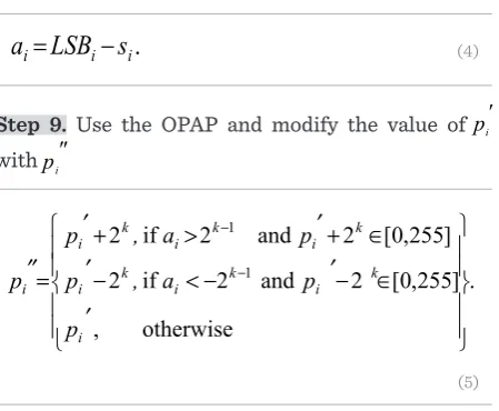
(4)Step 9. Use the OPAP and modify the value of pi′ with pi″
. otherwise , ] 255 , 0 [ 2 and 2 if 2 ] 255 , 0 [ 2 and 2 if 2 1 1 i k i k i k i k i k i k i i p p a , p p a , p p (5)
Step 10.Move to the next block and return back to Step 4.
Step 11. For embedding secret data bits using Oc-ta-PVD, use the obtained sub-ranges Rj from Step 4 to calculate the number of embedding secret bits (ti) for each pixel pair in the current block Bi. The number of embedding secret data bits can be calculated using the following equation:
).
1
(
log
2
i ii
u
l
t
(6) . otherwise ), ( 0 if , i i i i ii l b
d b l d (7) ). 7 ..., , 0 ( , 2 ) (
d d i
zi i i (8)
,
). () ,
(pi pi1 pi zi pi1 zi (9)
(6)
Step 12. For each pixel pair, read ti bits from the bi-nary bitstream S′ and convert them into its decimal value bi.
Step 13. Calculate eight new difference values di′ )
7 ..., , 0
(i= to replace the eight original difference
val-ues di (i=0,...,7)
).
1
(
log
2
i ii
u
l
t
(6) . otherwise ), ( 0 if , i i i i ii l b
d b l d (7) ). 7 ..., , 0 ( , 2 ) (
d d i
zi i i (8)
,
). () ,
(pi pi1 pi zi pi1 zi (9)
(7)
Step 14. Compute zi as follows:
).
1
(
log
2
i ii
u
l
t
(6) . otherwise ), ( 0 if , i i i i ii l b
d b l d (7) ). 7 ..., , 0 ( , 2 ) (
d d i
zi i i (8)
,
).( ) ,
(pi pi1 pi zi pi1 zi (9)
(8)
Step 15. Calculate new pixel pair values (pi′, pi+1′) using
).
1
(
log
2
i ii
u
l
t
(6) . otherwise ), ( 0 if , i i i i ii l b
d b l d (7) ). 7 ..., , 0 ( , 2 ) (
d d i
zi i i (8)
,
).( ) ,
(pi pi1 pi zi pi1 zi (9) (9)
Figure 3
Range table proposed in [40]
R1 = [0, 7] t1 = 3
R2 = [8, 15] t2 = 3
R3 = [16, 31] t3 = 4
R4 = [32, 63] t4 = 5
R5 = [64, 127] t5 = 6
R6 = [128, 255] t6 = 7
Step 7. For each pixel pi in the block and using the in-dices of pixels in Ns, replace the k-rightmost LSBs of the pixel pi by the k-leftmost bits of the bitstream S′ (k′ {3, 4}) to obtain stego pixel pi′. In addition, trans-form these k bits-LSBs from pi and k bits from the bi-nary bitstream S′ into their decimal values (call them
LSBi and si, respectively).
Step 16. Use the optimal reference point selection ap-proach (ORPSA) that will be explained later to select the optimal reference point from the resulting eight pixel pairs and then use it to modify the other seven pixel pairs.
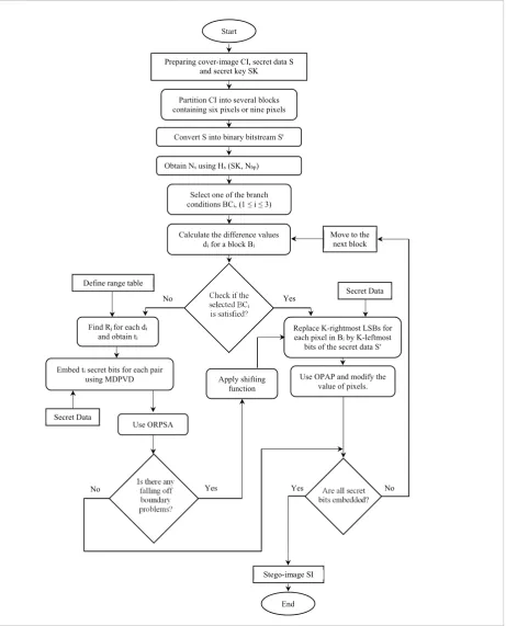
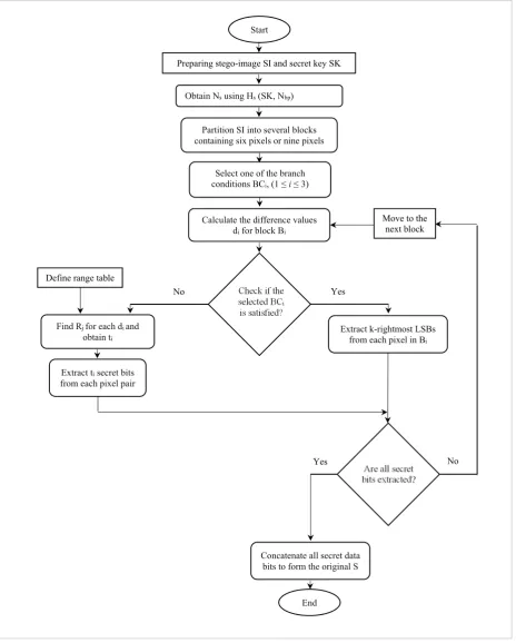
Step 17. If there is any falling-off-boundary cases happened, then use the shifting function and return back to Step 6 to re-embed this block using MLSB. Step 18. Move to the next block and go to Step 4 until all secret data bits are embedded in the cover-image. Notice that by using the shifting function, all blocks in the cover-image will be exploited to hide secret data bits, and thus giving higher embedding capacity. It is worth stating that the complexity time produced by our method is about O (n2) which is less than or equal to 59s. The embedding process is illustrated in Fig. 4. Optimal Reference Point
Selection Approach (ORPSA)
To achieve a minimum mean square error (MSE) and thus minimize stego-image distortion, the optimal reference point must be carefully obtained to adjust the other remaining gray values of the pixel pairs in each block. The authors of the TPVD algorithm [30] proposed optimal selection rules for obtaining the reference point according to mi values where mi =
di - di′. However, their rules for selecting the optimal reference point depend only on three values of ‘mi’ since there are three directional pixel pairs. Unfor-tunately, these rules are not applicable in this algo-rithm since there exist five or eight directional pixel pairs. Therefore, in this algorithm, a new function is proposed for selecting the optimal reference point for each block, depending on the calculations of the PSNR. Consequently, the optimal reference point can be obtained dynamically to ensure that the best selec-tion is acquired. The overall computaselec-tional complex-ities, induced by this method and TPVD method, are approximately the same.
Shifting function
One of the deficiencies of PVD method is the fall-ing-off-boundary problem. Therefore, a need to use a shifting function arises to modify one pixel value in the block Bito re-embed data in this block using MLSB method. Using shifting function in the proposed algo-rithm will somehow increase the embedding capacity.
Moreover, this modification for one pixel value rarely affects the overall visual quality of the stego-image significantly. The following steps describe how the shifting function works considering the following variables:
_ Mp is the maximum value in block Bi. _ Mip is the middle pixel in block Bi. _ BCi is the selected branch condition.
Step 1. Find the maximum pixel (Mp) among pixels in the block Bi excluding the middle pixel Mip.
Step 2. Let Omp = Mp.
Step 3. Increase Mp by 1 (i.e. Mp = Mp + 1). Then, com-pute dif = Mp – Mip.
Step 4. If only one difference value satisfies the se-lected BCi (i.e., if the selected branch condition is BC1, that means the condition will be “if the dif is equal or greater than 8”), then repeat Step 3 until this “if con-dition” is satisfied.
Step 5. If the Mp is not in the range of 0-255 (i.e. Mp
<0 or 255<Mp), then make Mp = Omp. Otherwise, go to Step 8.
Step 6. Increment Mp by 1 (i.e. Mp = Mp – 1). Then, compute dif = Mp – Mip.
Step 7. If dif does not satisfy the selected BCi, then re-peat Step 6 until the “if condition” is satisfied. Step 8. Modify the original value of the max pixel in the block Bi with Mp.
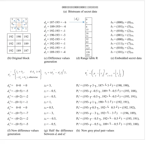
Embedding phase example
Assuming the bitstream of secret data is given as de-scribed in Fig. 5(a) and the sample sub-block for nine neighboring pixels is given as found in Fig. 5(b) where the sub-block has the gray-values of (192, 190, 192, 192, 193, 189, 192, 189, and 187). Consequently, the following are the outcomes (in sequence):
_ The difference values are generated as shown in Fig. 5(c).
_ Assuming branch condition 1 is used, all the difference values, in this sub-block, are less than 8. Thus, this block will be embedded using Octa-PVD where the optimal range for all pairs in this block is R1 = [0, 7] as shown in Fig. 5(d). Consequently, the number of secret data bits can be obtained as follows: ti =log2|7−0+1|=3bits,which will be
23 Information Technology and Control 2017/1/46
7
Yes Check if the
selected BCi is satisfied?
Is there any falling off boundary problems?
Are all secret bits embedded?
Secret Data
No
End
Stego-image SI
No Yes
Preparing cover-image CI, secret data S and secret key SK
Partition CI into several blocks containing six pixels or nine pixels
Calculate the difference values di for a block Bi Select one of the branch conditions BCi, (1 ≤ i ≤ 3)
Start
Convert S into binary bitstream Sꞌ
Yes
Replace K-rightmost LSBs for each pixel in Bi by K-leftmost bits of the secret data S′
Secret Data
Use OPAP and modify the value of pixels.
No
Find Rj for each di and obtain ti
Define range table
Embed ti secret bits for each pair
using MDPVD Apply shifting
function
Figure 4. The flowchart of the embedding procedure in MDPVD-MLSB algorithm. Obtain Ns using Hs (SK, Nbp)
Move to the next block
Use ORPSA
Figure 4
10
000101010001000111010101 (a) Bitstream of secret data
d0= 187-193 = - 6 b0 = (000)2 = (0)10,
d1 = 189-193= - 4 b1 = (101)2 = (5)10,
d2= 192-193 = -1 b2 = (010)2 = (2)10,
d3= 190-193 = -3 b3 = (001)2 = (1)10,
d4= 192-193 = -1 b4 = (000)2 = (0)10,
d5= 192-193 = -1 b5 = (111)2 = (7)10,
d6= 192-193 = -1 b6 = (010)2 = (2)10,
d7= 189-193 = -4 b7 = (101)2 = (5)10.
(b) Original block (c) Difference values
generation (d) Range table R (e) Embedded secret data
otherwise ), (
0 if ,
i b i l
i d i
b i l i
d zi (di di) 2,
i z i p i z i p
1 , i
P
d0ꞌ = 0+0 = 0 z0= 3, P0ꞌ = (193-┌ 3 ┐, 187+└ 3 ┘) = (190, 190),
d1ꞌ = - (0+5) = -5 z1= – 0.5, P1ꞌ = (193-┌ –0.5 ┐, 189+└ –0.5 ┘) = (193, 188),
d2ꞌ = - (0+2) = -2 z2= – 0.5, P2ꞌ = (193-┌ –0.5 ┐, 192+└ –0.5 ┘) = (193, 191),
d3ꞌ= - (0+1) = -1 z3= 1, P3ꞌ = (193-┌ 1 ┐, 190+└ 1 ┘) = (192, 191),
d4ꞌ = 0+0 = 0 z4= 0.5, P4ꞌ = (193-┌ 0.5 ┐, 192+└ 0.5 ┘) = (192, 192),
d5ꞌ = - (0+7) = -7 z5= – 3, P5ꞌ = (193-┌ – 3 ┐, 192+└ – 3 ┘) = (196, 189),
d6ꞌ = - (0+2) = -2 z6 = – 0.5, P6ꞌ = (193-┌ – 0.5 ┐, 192+└ – 0.5 ┘) = (193, 191),
d7ꞌ = - (0+5) = -5 z7= – 0.5, P7ꞌ = (193-┌ – 0.5 ┐, 189+└ – 0.5 ┘) = (193, 188).
(f) New difference values
generation (g) Half the difference between diand di′
(h) New grey pixel pair values
Figure 5 (a-h). An example of the embedding process in our Octa-PVD-MLSB scheme when using the branch
condition 1. Since all the difference values are less than 8, the Octa-PVD is used to embed secret data bits.
190 189 188 183 190 185 188 185 190
193 192 191 186 193 185 191 188 193
193 192 191 186 193 185 191 188 193 (a) Msb1, PSNR1 = 35.4201 (b) Msb2, PSNR2 = 38.5884 (c) Msb3, PSNR3 = 38.5884
192 191 190 185 192 187 190 187 192
192 191 190 185 192 187 190 187 192
196 195 194 189 196 191 194 191 196 (d) Msb4, PSNR4 = 38.0354 (e) Msb5, PSNR5 = 38.0354 (f) Msb6, PSNR6 = 35.7420
193 192 191 186 193 188 191 188 193
190 189 188 183 190 185 188 185 190 (g) Msb7, PSNR7 = 38.5884 (h) Msb8, PSNR8 = 35.4201
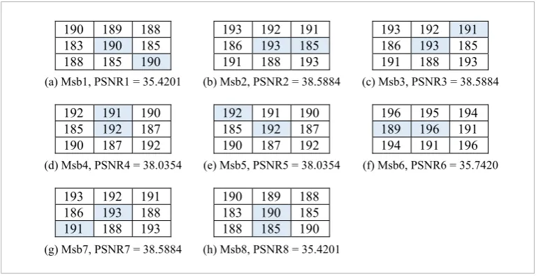
Figure 6 (a-h). Obtaining the optimal reference point for example 1.
0 7 8 15 16 31 32 63 64 127 128 255
| d0|
192 190 192
192 193 189
192 189 187
Figure 5 (a-h)
An example of the embedding process in our Octa-PVD-MLSB scheme when using the branch condition 1. Since all the difference values are less than 8, the Octa-PVD is used to embed secret data bits
_ Using the bitstream of secret data bits in Fig. 5(a), the embedded bits bi for each pixel pair will be as shown in Fig. 5(e).
_ The new eight difference values di′ can be generated as shown in Fig. 5(f).
_ zi values are computed as shown in Fig. 5(g).
_ The new pixel pairs are calculated as shown in Fig.5 (h). Therefore, the new pixel pairs will be as follows: {(190, 190), (193, 188), (193, 191), (192, 191), (192, 192), (196, 189), (193, 191), (193, 188)}. _ Finally, the optimal pixel pair can be found by using
25 Information Technology and Control 2017/1/46
1 When having the pixel pairs that are shown in Fig.5 (h), which are {P0′ = (190,190), P1′ = (193,188),
P2′ = (193,191), P3′ = 192,191), P4′ = (192,192), P5′ = (196,189), P6′ = (193,191), P7′ = (193,188)}, then the first pixel pair denoted by P0′ is the optimal refer-ence point. Consequently, the offsetting process for the other seven pixel pairs will be as follows:
P1′ = (193+190-193, 188+190-193) = (190,185),
P2′= (193+190-193, 191+190-193) = (190,188),
P3′= (192+190-192, 191+190-192) = (190,189),
P4′ = (192+190-192, 192+190-192) = (190,190),
P5′= (196+190-196, 189+190-196) = (190,183),
P6′ = (193+190-193, 191+190-193) = (190,188), P7′ = (193+190-193, 188+190-193) = (190,185). The re-sulting pixel pairs are shown in the modified sub- block ‘Msb1’ that is shown in Fig. 6 (a). After that, the PSNR of Msb1 is found.
2 Moving to the second pixel pair ‘P1′’ and assuming it is the optimal reference point, the same proce-dure done in Step 1 is considered to offset the other remaining pixel pairs in order to obtain ‘Msb2’ and calculate its PSNR value.
3 Repeating the same work performed in Steps 1 and 2 for the rest of pixel pairs.
4 Obtaining a total of eight modified sub-blocks )
,...,
(msb1 msb8 and eight values of the PSNR, as shown in Fig. 6 (a-h). As depicted in Fig. 6 (a-h), the optimal reference pair may be one of the following pixel pairs: {2, 3, or 7} since all of them achieve the highest PSNR (i.e., PSNR =38.5884). For
simplici-ty, the first one is proposed to be dynamically cho-sen. Thus, the final embedded block is the Msb2, as illustrated in Fig. 6 (b).
Extracting phase
To extract secret data bits correctly from each block
Biin a stego-image SI, the following steps are consi- dered:
Input: A W × H stego-image SI, range table R and se-cret key SK.
Output: The secret data S.
Step 1. Partition SI into 3×3 non-overlapping sub-blocks.
Step 2. As in the embedding phase, obtain Ns accord-ing to Hs (SK, Nbp).
Step 3. Choose the same branch condition that is se-lected by the embedding algorithm BCi (1≤i≤ 3). Step 4. Repeat Step 2 in the embedding phase to cal-culate the difference values di′ (0 ≤i≤ 7) for eight pixel pairs.
Step 5. If the branch condition is satisfied, then ex-tract this block by using MLSB. Otherwise, exex-tract this block by using Octa-PVD and apply Steps from 8 to 10.
Step 6. Extract the secret bits si from k-rightmost LSBs of each pixel pi′ in this sub-block. As in the em-bedding process, the secret bits are extracted accord-ing to the pixel indices in Ns set.
Figure 6 (a-h)
Obtaining the optimal reference point for example 1
10
000101010001000111010101 (a) Bitstream of secret data
d0= 187-193 = - 6 b0 = (000)2 = (0)10,
d1 = 189-193= - 4 b1 = (101)2 = (5)10,
d2= 192-193 = -1 b2 = (010)2 = (2)10,
d3= 190-193 = -3 b3 = (001)2 = (1)10,
d4= 192-193 = -1 b4 = (000)2 = (0)10,
d5= 192-193 = -1 b5 = (111)2 = (7)10,
d6= 192-193 = -1 b6 = (010)2 = (2)10,
d7= 189-193 = -4 b7 = (101)2 = (5)10.
(b) Original block (c) Difference values
generation (d) Range table R (e) Embedded secret data
otherwise ), (
0 if ,
i b i l
i d i
b i l i
d zi (di di) 2,
i z i
p i z i p
1 , i
P
d0ꞌ = 0+0 = 0 z0= 3, P0ꞌ = (193-┌ 3 ┐, 187+└ 3 ┘) = (190, 190),
d1ꞌ = - (0+5) = -5 z1= – 0.5, P1ꞌ = (193-┌ –0.5 ┐, 189+└ –0.5 ┘) = (193, 188),
d2ꞌ = - (0+2) = -2 z2= – 0.5, P2ꞌ = (193-┌ –0.5 ┐, 192+└ –0.5 ┘) = (193, 191),
d3ꞌ= - (0+1) = -1 z3= 1, P3ꞌ = (193-┌ 1 ┐, 190+└ 1 ┘) = (192, 191),
d4ꞌ = 0+0 = 0 z4= 0.5, P4ꞌ = (193-┌ 0.5 ┐, 192+└ 0.5 ┘) = (192, 192),
d5ꞌ = - (0+7) = -7 z5= – 3, P5ꞌ = (193-┌ – 3 ┐, 192+└ – 3 ┘) = (196, 189),
d6ꞌ = - (0+2) = -2 z6 = – 0.5, P6ꞌ = (193-┌ – 0.5 ┐, 192+└ – 0.5 ┘) = (193, 191),
d7ꞌ = - (0+5) = -5 z7= – 0.5, P7ꞌ = (193-┌ – 0.5 ┐, 189+└ – 0.5 ┘) = (193, 188).
(f) New difference values
generation (g) Half the difference between di and di′
(h) New grey pixel pair values
Figure 5 (a-h). An example of the embedding process in our Octa-PVD-MLSB scheme when using the branch condition 1. Since all the difference values are less than 8, the Octa-PVD is used to embed secret data bits.
190 189 188 183 190 185 188 185 190
193 192 191 186 193 185 191 188 193
193 192 191 186 193 185 191 188 193 (a) Msb1, PSNR1 = 35.4201 (b) Msb2, PSNR2 = 38.5884 (c) Msb3, PSNR3 = 38.5884
192 191 190 185 192 187 190 187 192
192 191 190 185 192 187 190 187 192
196 195 194 189 196 191 194 191 196 (d) Msb4, PSNR4 = 38.0354 (e) Msb5, PSNR5 = 38.0354 (f) Msb6, PSNR6 = 35.7420
193 192 191 186 193 188 191 188 193
190 189 188 183 190 185 188 185 190 (g) Msb7, PSNR7 = 38.5884 (h) Msb8, PSNR8 = 35.4201
Figure 6 (a-h). Obtaining the optimal reference point for example 1. 0
7 8 15 16 31 32 63 64 127 128 255
| d0|
192 190 192
192 193 189
Step 7. Move to the next block and then return back to Step 4.
Step 8. Find the value of lower bound liby obtaining
the optimal range Ri.
Step 9. Extract the embedding secret data bits from each pixel pair in a block using:
. | | i i
i d l
s (10)
Move to the next block and then go to Step 4 until the recovery process of all the secret bits is finished. Then, concatenate all the secret bits si in the same or-der as in the embedding process to obtain S′. Finally, convert S′ to form the original secret data S.
The extraction process is illustrated in the flowchart shown in Fig. 7.
It is noteworthy to mention that all of the side in-formation used in this algorithm such as the secret key and the branch condition are offline, except the amount of the payload which occupies only 32 bits of the embedding capacity.
Experimental results and discussion
In this section, the performance of the proposed algo-rithm is evaluated, discussed and justified.Firstly, the simulation setup and its parameters are introduced. Secondly, a detailed description of the used metrics is presented. Lastly, the simulation re-sults and comparisons are presented.
Simulation setup Simulation parameters
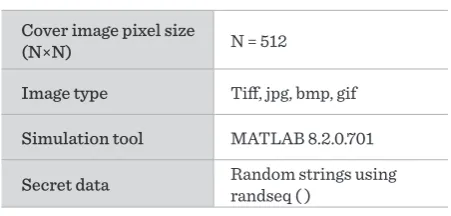
The proposed algorithm has been implemented and simulated using MATLAB 8.2.0.701 (R2013b) on Windows 7 platform with an Intel Core i7-4600U CPU working at 2.1 GHz with a 4 MB cache and 4 GB RAM. The results for different grayscale im-ages are obtained for various random secret data. The various simulation parameters are as given in Table 2.
Performance metrics
The performance of the proposed algorithms was evaluated in terms of imperceptibility and embedding capacity which are defined as follows:
Table 2
Simulation parameters
Cover image pixel size
(N×N) N = 512
Image type Tiff, jpg, bmp, gif
Simulation tool MATLAB 8.2.0.701
Secret data Random strings using randseq ( )
_ Imperceptibility: To measure the imperceptibility or the perceptual quality of a stego-image, the PSNR is used as well as the structural similarity index measure (SSIM) metrics. PSNR is the simplest and most widely used metric [48-51]. It can be found as follows [40, 47]:13
, 255 log
10 10 2
MSE ) ( PSNR (11)
where the value 255 refers to the maximum value of the pixel intensity for 8-bit grayscale images and MSE is the mean square error, which is used to compute the average square of the difference between the grey-scale cover image and its stego-image and is calculated using [52-56]:
. ) ( 1 1 0 1 0 2 M i N
j xij xij
N M
MSE (12)
In this equation, “M×N” represents the size of the cover-image and stego-image. In addition, xij and xijꞌ represent the pixel values at certain index (i, j) of the cover-image and stego-image, respectively. In general, to keep the grayscale cover-image and stego-image indiscernible to the human eye, a high value for the PSNR should be kept. Thus, a high PSNR means that the cover-image and stego-image are very similar to each other whereas a low PSNR means the opposite [57-58]. Besides PSNR, which is error-based metric, SSIM is very popular due to the fact that the human visual system is highly sensitive to structural information. In other words, any loss of structural data can give a good approximation for distortion of the perceived image. However, if the cover and stego images are
defined asx and y,respectively, then SSIM is computed using [59]:
, ) ( ) ( ) 2 )( 2 ( ) , ( 2 2 2 1 2 2 2 1 C C C C y x SSIM y x y x xy y x (13)
where
xandx2refer to the mean and variance ofx
, respectively, yand y2 refer to the mean and variance ofy , respectively, xy denotes for the covariance ofxand . y C1(k1L)2andC2(k2L)2aretwo constants required to stabilize the division when the mean and variance get close to zero, where 03 . 0 , 01 . 0 2
1 k
k , and L2Nbpp 1(where Nbpp is the number of bits per pixel), representing the
maximum possible value of the image pixel. It is good to mention that the results of SSIM fall within the range of {0, 1} in which ‘1’ indicates that the two images are completely identical, while ‘0’ indicates that the two images are entirely different. However, for each image, there are several SSIM indices where each one is calculated within 11 × 11 local window using a certain circular-symmetric Gaussian weighting value (between 0 and 1) and the final SSIM image index is the average of these indexes.
Embedding Capacity (EC): The embedding capacity is defined as the number of secret data bits that
can be hidden in a cover-image. It is also known as embedding rate (ER), which represents the number of secret data bits that can be hidden per pixel, that is basically measured as the ratio of the total number of embedded secret bits to the total number of pixels in a cover-image. Actually, whenever this ratio exceeds one, it indicates that the steganographic embedding scheme has high embedding capacity [3, 19]. It can be calculated as follows:
EC = Total number of embedded secret bits. (14)
). pixel bits ( CI in pixels of number Total bits secret embedded of number Total
ER (15)
(bpp). N M EC ER (16)
4.2. Experimental results
In our experiments, eight 8-bit 512x512 benchmark images, which are obtained from USC-SIPI Image
database and UWATERLOO-LINKS Image Repository [60, 61], are used. These grayscale images namely Lena,
Peppers, Boat, Jet, Splash, Airplane, Baboon and Tiffany are shown in Fig. 8 (a-h). Data to be embedded is randomly generated. The range table used in the experiments is shown in Fig. 3. The maximum embedding capacity in this method can be calculated as follows:
1. Find the embedding capacity for MDPVD blocks:
(11)
where
the value 255 refers to the maximum value of the pix-el intensity for 8-bit grayscale images and MSE is the mean square error, which is used to compute the av-erage square of the difference between the grey-scale cover image and its stego-image and is calculated us-ing [52-56]:
13
, 255 log
10 10 2
MSE ) ( PSNR (11) . ) ( 1 1 0 1 0 2 M i N
j xij xij
N M MSE (12) , ) ( ) ( ) 2 )( 2 ( ) , ( 2 2 2 1 2 2 2 1 C C C C y x SSIM y x y x xy y x (13) 2 2
EC = Total number of embedded secret bits. (14)
). pixel bits ( CI in pixels of number Total bits secret embedded of number Total
ER (15)
(bpp). N M EC ER (16) (12)
![Fig. 1 (a, b) shows the block structures for the two SK [1,362880 ]SK [1,362880 ]](https://thumb-us.123doks.com/thumbv2/123dok_us/8765101.1754025/4.595.307.532.425.664/fig-b-shows-block-structures-sk-sk.webp)