Area Efficient Turbo Encoder for Wireless Applications
on FPGA
Mansi Rastogi
ME Student (ECE), NITTTR Chandigarh, UT, India Email: [email protected]
Rajesh Mehra
Associate Professor, ECE Department NITTTR Chandigarh, UT, India
Abstract – Error control is the major insistence in today’s
wireless communication systems. In this era parallel concatenated convolutional codes known as turbo codes plays a crucial role. These codes have been chosen as error control approach for various wireless applications such as UMTS (Universal Mobile Telecommunication System),DVB (Digital Video Broadcasting) etc. In this paper an area efficient turbo encoder (2, 1, 3) is proposed to suffice the elevated demand of miniaturization in future wireless communication. The proposed design is simulated using matlab and synthesized on Xilinx Virtex-2p (xc2vp30-ff896-5) FPGA. During simulation the proposed design is compared with the matlab model of RSC encoder. The performance of proposed Turbo encoder will be compared for FPGAs in terms of number of slices, number of slice Flip-flops and the number of registers. The Synthesis results show a 7% improvement in the utilized no. of slices and slice flip-flop. So an area efficient, cost effective Parallel Concatenated Convolutional Code Encoder has been proposed in this paper.
Keywords – Parallel Concatenated Convolutional Code, Recursive Systematic Convolutional Encoder, Forward Error Correction, Convolutional Code, FPGA.
I.
I
NTRODUCTIONThe wireless communication system is highly error prone due to its channel deterioration such as noise and interference etc. To overcome these impairments, there is a need of channel coding. In this era ECC (Error Control Codes) are used. The Turbo Codes, introduced in 1993, and LDPC (Low Density Parity Check) codes are the two ECC, approaches the Shannon capacity limit. In ECC, redundancy will be added to the information data and send over the noisy channel. At the receiver end the data will be checked and corrected for the error incurred during the transmission. The performance of Turbo and LDPC codes over vehicular ad-hoc networks based on IEEE 802.11p specifications has been investigated [1]. In general wireless communicationsystems, LDPC and Turbo codes provide powerful errorcorrection capability, especially in mobile environmentswith low signal-to-noise ratio.The FPGA implementation of these codes shows that the Turbo code outperforms the LDPC codes in terms of area utilization and delay.
The multicarrier CDMA supports the high coding rate, high utilization of the frequency spectrum. It also gives good performance of overcoming multipath fading. A model of Turbo code based on OFDM-CDMA (Orthogonal Frequency Division Multiplexing and Code Division Multiple Access) is proposed [2]. Three parts are there, channel code, extending frequency and the modulation of the multicarrier, gives high reliability and good capability of overcoming multipath fading.The Turbo
code based on OFDM-CDMA is superior to the ones that using the AWGN model.FPGA based system is faster and consumes less energy than the software based system [3]. The FPGA based design of turbo codec is simulated using ModelSim. The encoder and decoder are based on the Log-MAP decoding algorithm. The FPGA-based Turbo Codec is able to estimatecorrectly the information sequence.
The performance of Turbo Codes is depending on various parameters [4] such as constraint length (number of states), code rate, block length (information data) and number of iteration etc. The use of turbo code with a reduced number of states causes the deterioration of transmission qualitycompared to the UMTS standard turbo code, but reduces the delay. The processing time and transmission quality are two inverse parameters. Several methods have been proposed to increase the performance and decrease the complexity of turbo codes. Path pruning and puncturing are employed for the construction of recursive systematic convolutional turbo encoders, so that the rate and complexity both can be improved[5]. This will results in flexible turbo code construction.
Till now turbo codes have been established as an error correcting code with very high performance in wireless communication. In this paper an area efficient turbo encoder design is proposed.This work is organized as follows. Section II includes the serial and parallel concatenated turbo encoder, also the methodology of turbo encoder used in this paper has been discussed. Simulation graphs have been shown in section III. A performance evaluation of Hardware Synthesis using FPGA is given in section IV. Finally, the conclusions are summarized in section V.
II.
T
URBOE
NCODERWhenever in wireless communication systems high error correction performance is required, Turbo Codes are ordinarily used. These codes can have two types of structures [6], serial concatenated and parallel concatenated structure. The serial concatenated encoder uses a convolutional encoder block to encode a data frame, a random interleaver block to shuffle the bits in the codeword, and another convolutional encoder block to encode the interleaved bits. Because these blocks are connected in series with each other, the resulting code is called a serially concatenated code. The serial concatenated encoder is shown in figure 1.
Copyright © 2014 IJECCE, All right reserved In this paper, the turbo code used parallel concatenated
structure. Adaptive parallel concatenation technique [7] has been proposed to further improve the performance. The turbo encoder is constructed by parallel concatenation of two RSC (Recursive Systematic Convolutional) encoders. The generator polynomials of these two RSC encoders are given in equation 1 and 2.
G = [1, g2/g1] (1)
G D = [ 1 (1 + D2)/(1 + D + D2 )] (2)
In the above representation, output represent as 1 denotes the systematic output, g2 denotes the feed-forward output, and g1 is the feedback to the input of the RSC encoder.The parameters for turbo code encoder are shown in table 1.
Table 1: List of turbo encoder specifications
No. of Input Sequence 1
No. of Output Sequence 3
Code Rate 1/3
Constraint Length 3
Encoder Type RSC
Polynomial Generator in Octal Notation (7,5)8
Feedback Generator 7
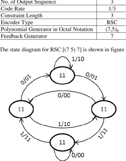
The state diagram for RSC [(7 5) 7] is shown in figure 2.
Fig.2. State Diagram for RSC Encoder
The RSC encoder has four possible memory states (00), (01), (10) and (11) for two registers. There are two branches leaving each state, since the encoder accepts only one input bit at a time, which can take two possible values causing an equal number of state transitions. Each branch is labeled with the input bit and the output bits generated by the RSC encoder. The parallel concatenated convolutional code turbo encoder is shown in figure 3.
The input to the second encoder is interleaved using block interleaver. Due to this the input to encoder 1 is delayed so that both the encoders will receive the input at the same time. The interleaver and delay used in this are double buffered so that it can allow a new block to be loaded while the current block is to be processed.
Fig.3. Turbo Encoder
A.
Interleaver
In an interleaver the input and output bits are same as input but in a different temporal order. In turbo code design the choice of the interleaver is a crucial part. In this the input bits are permuted in a matrix, such that the interleaver output is a pseudo-random string of the input bits. This has two advantages. Firstly, if the input to the second encoder is interleaved, its output is entirely contrasting from the output of the first encoder. This means that there is a smaller chance of producing an output with very low weight or higher weight output because if one of the outputs has low weight, the other does not have. Also, it is used to increase the weights of the codeword. Secondly, if the input to the second decoder is scurry, its output will also be different from the output of the first encoder. This means the interleaving converts by linking easily error-prone code and burst errors together with error free code. If a burst error is crooked a block of letters in the middle of the information message. It is impossible to recover that information signal without interleaver. By using interleaving, it spreads out the signal before sending it to the noisy channel and the text is much easier to derive after deinterleaving. The permutation matrix is based on the number of bits per block. There are various types of interleaver, out of random (pseudo random) interleaver is used in this thesis shown in figure 4. The random interleaver uses a fixed random permutation and maps the input sequence according to the permutation order. The interleaver writes in [0 1 1 0 1 0 0 1] and reads out [0 1 0 1 1 0 1 0].
Fig.4. A Random Interleaver with L=8
III.
P
ROPOSEDD
ESIGNS
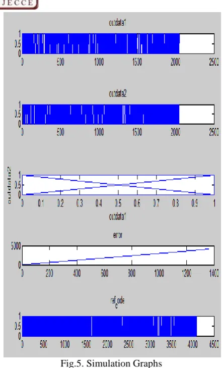
IMULATIONSFig.5. Simulation Graphs
The outdata1 represents the quantized value of the first output of recursive systematic convolutional encoder. The second quantized value is represented by outdata2. The third one is for outdata2: outdata1. Fourth one represents the error. The proposed model is verified against the referenced Matlab model. If they matched then error=0 and comparison graph results in a straight line shown in figure 6. If they did not matched then error=1 and graph will result in a line shown in the fourth graph of figure 5. The fifth one graph of figure 5 represents the ref_code generated by Matlab model. This will come out serially. The output of turbo encoder is shown in figure 7. It will result in the value of +1 and -1.
Fig.6. Simulation Graph of matched model
Fig.7. Simulation Graph of turbo encoder
IV.
FPGA
I
MPLEMENTATIONR
ESULTSField Programmable Gate Array (FPGAs) is a reconfigurable devices designed by using a HDL (Hardware Description language). The proposed design is implemented using VHDLand synthesized on Xilinx Virtex-2p (xc2vp30-ff896) FPGA with a speed grade of -5. The synthesis tool used to measure the performance of proposed decoder is ISE 10.1. The RTL view of Turbo encoder is shown in figure 8.
Fig.8. RTL View
The resource utilization summary of proposed turbo encoder is given in table 2.
Table 2: Resource Utilization Summary xc2vp30ff896-5
Logic Utilization Used Utilization
Number of slices 154 1%
Copyright © 2014 IJECCE, All right reserved
Number of 4 i/p LUTs 277 1%
Number of bonded IOBs 56 10%
Number of GCLKs 1 6%
Number of BRAM 2 1%
No. of adder & Subtractor 5
No. of Counter 1
No. of registers 162
Frequency 114.736
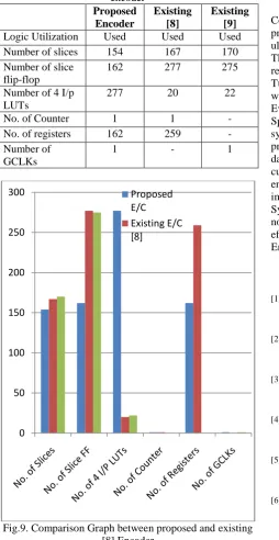
The parameters used in the resource utilization are number of slices, slice flip-flop, 4 I/P LUTs, counters and registers etc. The comparison table between the proposed encoder and existing encoders has been shown in table 3 and the bar graph in figure 9.
Table 3: Comparison table between proposed and existing encoder Proposed Encoder Existing [8] Existing [9] Logic Utilization Used Used Used
Number of slices 154 167 170
Number of slice flip-flop
162 277 275
Number of 4 I/p LUTs
277 20 22
No. of Counter 1 1 -
No. of registers 162 259 -
Number of GCLKs
1 - 1
Fig.9. Comparison Graph between proposed and existing [8] Encoder
In [8], the turbo encoder is synthesized using Xilinx ISE 10.1. The parameters for the comparison are no. of slices, counters and registers etc. As shown in the graph the utilized no. of slices, slice FF, Counter and registers are less as compared to [8]. The proposed encoder results in an optimized area performance. In [9], a comparative analysis of turbo and LDPC encoders has been given in terms of power and device utilization. The parameters for the comparison are no. of slices, slice FF and GCLKs etc. As shown in the graph, the proposed encoder utilized less no. of resources in terms of no. of slices and slice FF. The proposed encoder results in an optimized area performance.
V.
C
ONCLUSIONIn this paper the Parallel Concatenated Convolutional Code Encoder design is proposed. These codes are mostly preferred in wireless communication as they achieve the ultimate limits of the capacity of communication channel. These codes are very useful for those applications where a reliable transmission is required even the SNR is low. Turbo Codes as error correcting codes are used in various wireless applications such as WiMAX, LTE (Long Term Evolution), DVB and CCSDS (Consultative Committee for Space Data Systems) etc. The proposed encoder is synthesized using Xilinx virtex2p (xc2vp30-ff896-5). In proposed encoder a buffering scheme is used so that a new data block can be uploaded during the processing of the current block. The comparison is made with existing encoders [8] and [9] and it shows a remarkable improvement in the utilized number of resources. The Synthesis results show a 7% improvement in the utilized no. of slices and slice flip-flop. So an area efficient, cost effective Parallel Concatenated Convolutional Code Encoder has been proposed in this paper.
R
EFERENCES[1] George Kiokes and George Economakos, “Performance analysis and complexity study of LDPC and Turbo Coding schemes for Inter Vehicle Communications,” IEEE Conference on ITS Telecommunications (ITST), pp. 559-564, August 2011. [2] Liu Na, Shi Wenxiao and Wu Jiang, “A Model of Turbo Code
Based on OFDM-CDMA,” IEEE conference on Wireless Communications, Networking and Mobile Computing, pp. 1-4, September 2006.
[3] Wen-Chen Hu, and Anlei Wang, “Performance Evaluation of a Turbo Codec with Log-MAP algorithm on FPGA and CPU,” IEEE International Conference on Electro/Information Technology (EIT), pp. 1-6, May 2011.
[4] AndrzejMarczak, “Comparison of the Efficiency of Turbo Codes with Different Number of States,” IEEE Conference on Telecommunications and Signal Processing (TSP), pp. 160-164, August 2011.
[5] AlexandrosKatsiotis and Nicholas Kalouptsidis, “Recursive Flexible Convolutional Encoders for Parallel Concatenation,” IEEE International Symposium on Turbo Codes and Iterative Information Processing (ISTC), pp. 250-254, August 2012. [6] NashatAbughalieh and Kris Steenhaut, “Parallel Concatenation
vs. Serial Concatenation Turbo Codes for Wireless Sensor Networks,” IEEE Symposium on Communications and Vehicular Technology (SCVT), pp. 1-6, November 2011.
[7] NashatAbughalieh and Kris Steenhaut, “Adaptive Parallel Concatenation Turbo Codes for Wireless Sensor Networks,” IEEE Conference on Communications and Information Technology (ICCIT), pp. 180-183, March 2011.
[8] S. Kahkashan and R. Badar, “Optimizing the Performance of Turbo Code HDL Model for Rapid Prototype,” IEEE Internation Conference on Emerging Technologies, pp. 352-357, 2009 [9] Sohaib A. and S. Kahkashan, “A Comparative Analysis of
Power and Device Utilization of LDPC and Turbo Encoders,” IEEE Conference on Infirmation and Communication Technologies (ICICT), pp. 1-5, 2011.
A
UTHOR’
SP
ROFILEMansi Rastogi
Miss Mansi Rastogi is pursuing her M.E. in Electronics and Communication Engineering from NITTTR, Chandigarh, India. She has done her B. Tech in Electronics and Communication Engineering from BIT U.P., India. Her areas of interest are Wireless Communication, Signal processing, embedded system design. Her current research is also based on Wireless Communication and Signal processing.