Organized by C.O.E.T, Akola & IWWA, Amravati Center. Available Online at www.ijpret.com373
INTERNATIONAL JOURNAL OF PURE AND
APPLIED RESEARCH IN ENGINEERING AND
TECHNOLOGY
A PATH FOR HORIZING YOUR INNOVATIVE WORK
SPECIAL ISSUE FOR
NATIONAL LEVEL CONFERENCE
"SUSTAINABLE TECHNOLOGIES IN
CIVIL ENGINEERING"
DEVELOPING TEMPERATURE CONTROL TECHNOLOGY UTILIZING A
MIST-COOLING SYSTEM FOR DEVICES THAT GENERATES HIGH TEMPERATURE
PROF. S. R. THAKARE1, PROF. S. C. MAKWANA2
1. Assistant Professor Department of Production Engineering, College Of Engineering and Technology, Akola. 2. HOD Department of Mechanical Engineering, College Of Engineering and Technology, Akola
Accepted Date: 13/03/2015; Published Date: 01/04/2015
Abstract: The increasingly advanced functions and high performance of semiconductor devices is
accompanied by a trend toward higher heat generation in these devices year by year. Although semiconductor devices are given uniform temperature burn-in testing at the final inspection of the manufacturing process, it is becoming increasingly difficult to control the uniform temperature because of the high heat generation of the device itself. Temperature control methods include such approaches as air cooling, water cooling, and heat pipes. However, cooling capacity is not the only requirement of burn-in testing. Other requirements include high temperature control capacity and system miniaturization. It should be noted that the methods listed above are not adequate to fulfil these requirements. In response to this situation, we have undertaken to provide a mist cooling system. By taking advantage of the latent heat of water, the mist cooling system is able to instantaneously dissipate a large amount of heat.
Keywords- Mist-Cooling, Temperature, Latent Heat.
.
Corresponding Author: PROF. S. R. THAKARE
Co Author: PROF. S. C. MAKWANA
Access Online On:
www.ijpret.com
How to Cite This Article:
Organized by C.O.E.T, Akola & IWWA, Amravati Center. Available Online at www.ijpret.com374 INTRODUCTION
In recent years, the growing trend toward miniaturization in manufacturing processes for devices using semiconductors has led to an increase in the number of transistors that these devices can employ, and manufacturers are striving to provide ever more advanced functions in tandem with higher performance. However, this miniaturization in manufacturing processes has resulted in an increased incidence of leak current along with a rising tendency toward greater heat generation by these devices. This heat generation has made it increasingly difficult to design equipment using these devices and device manufacturers are fashioning countermeasures aimed at reducing heat generation. However, at present it is impossible to avoid the increased heat generation that accompanies the more advanced functions and higher performance in these devices. Mass production is already under way for devices in which the heat generation exceeds 100 watts, and mass production is projected for devices with even higher heat generation in the future.1
During the final inspection of the manufacturing process, semiconductor devices are subjected to burn-in testing in which they are exposed to temperatures and usage voltage that are higher than those found in normal use. Conventional burn-in tests control the device temperature by injecting cooled air into the ambient environment. However, as devices have come to generate greater amounts of heat, it is becoming more and more difficult to control device heat generation with the ambient air atmosphere. As a result, cooling methods capable of handling such high-heat-generating devices are now required.
In this report, we would like to discuss the development of cooling technology using mist, which can be considered quite advantageous for its cooling capacity and temperature control capacity.
2. Mist Cooling Methods and their Cooling Principles
2.1 Mist Cooling Methods
Organized by C.O.E.T, Akola & IWWA, Amravati Center. Available Online at www.ijpret.com375 unit of surface measurement. In addition, spraying miniaturized droplets of liquid makes it difficult for the liquid to build up on the heat-generating surface, thus improving the efficiency of the phase change effect.
Fig. 2.1 .Mist spray condition
2-2 Mist cooling features.
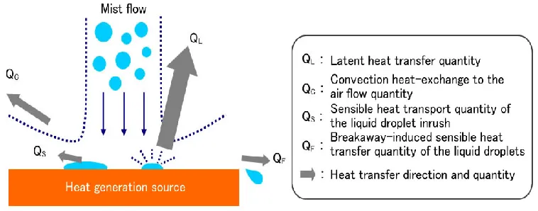
The total amount of mist-cooled heat quantity Q consists of the latent heat transfer quantity QL produced by droplet evaporation, the convection heat-exchange quantity of= the air flow QC, the sensible heat transfer quantity of the liquid droplet inrush QS, and the breakaway-induced sensible heat transfer quantity of the liquid droplets QF. This can be expressed as
Q = QL + QC + QS + QF
Organized by C.O.E.T, Akola & IWWA, Amravati Center. Available Online at www.ijpret.com376 The equipment configuration used for this research has extremely small values QS and QF for coolant retention and coolant breakaway on the surfaces being cooled. With the specific heat capacity of air being 1.0 kJ/kg K, using water as the coolant results in latent heat of 2431 kJ/kg
(300).3) With an air/water ratio of 3:1 by mass for the mist flow, when the temperature change
is 400 after the mist has been sprayed, the heat transfer capacity for the latent heat of water is
approximately 20 times greater than with air cooling. This means that the heat quantity transferred by the latent heat of the mist cooling in this case results in control of the quantity of heat. In this way, mist cooling is able to effect cooling primarily by utilizing the latent heat of the coolant. This makes it possible to vary the amount of cooling using much smaller fluctuations in the amount of coolant than with methods such as water cooling. This effectively makes it possible for mist cooling to handle a much greater range of heat generation quantity on an identical system. It also makes it possible for the mist cooling system to respond easily to abrupt changes in the amount of heat generated
3. Experimental Method
3-1 Evaluation subject and temperature control points
A simulated dummy heater was used along with the actual test device for evaluating cooling capacity. This layout consisted of sandwiching the heater plate between a metal cover and a resin plate, similar to a typical high-heat-generating device of a type currently being manufactured.
To obtain the correlation between the temperature characteristics of the actual test device and the dummy heater, we took the assumed burn-in testing time of the actual test device in Fig.3.1 (a), and then we selected the temperature control point shown in Fig.2 (b) for the dummy heater as being a control point that would yield equivalent temperature characteristics for the cooling time required by the assumed burn-in testing time of the actual test device
Organized by C.O.E.T, Akola & IWWA, Amravati Center. Available Online at www.ijpret.com377 Fig3.1 (b) Dummy heater (Cross-sectional diagram)
Fig 3 Layout of evaluation subjects and temperature control points
We were able to confirm that the actual test device and the dummy heater evidenced no great difference in temperature characteristics for the control points of both devices, and showed a rough correlation in cooling performance
3-2 Experimental Equipment and Conditions
Fig.3.2 shows the layout of the experimental equipment. Mist was sprayed using a spray nozzle that combined high pressure air and liquid. The mist spray amount was adjusted using control valves provided on circuits for the air and water combined under pressure in the spray nozzle to produce the mist spray features. This was used for the desired dummy heater temperature control. The liquid used for the mist was water, due to its great evaporation latent heat and relative ease of handling.
Organized by C.O.E.T, Akola & IWWA, Amravati Center. Available Online at www.ijpret.com378 Table 1 shows the experimental conditions. Special temperature control was not performed
on the air and water used for the mist spray, with the experiment conducted at room
temperature (approximately 250).
Table: 1 Experimental condition
Control subject (heater) heat generation amount 30 W to 300 W
Control temperature 1000 to 1800
Control subject surface area 40 mm x 40 mm
Target temperature control range ±30
Control atmosphere Ambient temperature: approx. 250 Water temperature: approx. 250 Air temperature: approx. 250
4. Experiment Results and Considerations
To verify cooling performance, we assumed device operation conditions under burn-in testing, and then we checked the heat dissipation performance both for static heat generation with only slight fluctuations in the amount of heat generated as well as for dynamic heat generation with abrupt fluctuations in the amount of heat generated.
4-1 Cooling performance with Static Heat Generation
Fig.4.1 shows the results for the dummy heater in regard to both quantity of heat generated
and control temperature fluctuations. With the control temperature set at 1300, we were able
to achieve our targeted mist cooling temperature control within ±30 for the range of 90 to 240
watts. The control performance depends on the control temperature, and mist evaporation
became unstable at temperature control points of 1200 or less, making it impossible to achieve
Organized by C.O.E.T, Akola & IWWA, Amravati Center. Available Online at www.ijpret.com379 cooled surface from the heat-generating source. Doing so could enable mist cooling to efficiently cool heat-generating levels of 200 to 300 watts and possibly more.
Fig.4.1 Relationship between heat generation quantity and control temperature (Temperature control range)
4-2 Cooling performance in dynamic heat generation
Using a dummy heater and instantaneously (maximum 0.5 seconds) fluctuating the heat generation quantity, we evaluated the responsiveness of temperature control for mist cooling of dynamic heat generation. At this time, using the guideline of controllability via differences in the fluctuation amount of heat generation, we set the heat generation quantity fluctuation ranges at ⊿30 watts, ⊿60 watts, and ⊿90 watts, and performed the experiments. Fig.4.2 shows the responsiveness of temperature control for ⊿60 watts. In this case, a temperature overshoot
of 100 occurred after a change in the quantity of heat generated, but within approximately 15
seconds there was a convergence to within ±30 of the control temperature
Organized by C.O.E.T, Akola & IWWA, Amravati Center. Available Online at www.ijpret.com380 Fig.4.2.1 shows the temperature controllability for each heat generation range of fluctuation. These temperature control disturbances that were caused by fluctuations in heat generation quantity were chiefly due to the responsiveness of the nozzle water flow. Raising the water pressure would make it possible to improve the responsiveness. However, doing so would tend to cause a loss of stability in the spray quantity, and so we did not raise the water pressure, instead giving priority to the stability of the spray quantity.
Fig.4.2.1 Relationship between the fluctuation range of heat generation and overshoot values
5. CONCLUSION
The results of developing mist cooling temperature control technology for high-heat-generating devices revealed the following
(1) Using mist cooling, it was possible to control the temperature of high-heat-generating devices.
(2) Using mist cooling to control temperatures of 1300 and above, it was possible to control the
temperature within ±30 for static heat generation in the range from 90 watts to 240 watts.
(3) With dynamic heat generation that produces abrupt fluctuations, an overshoot of 100
appeared in the heat generation fluctuation range of ⊿60 watts immediately following the
fluctuation in heat generation, but following the overshoot the temperature control was able to
converge once again to within ±30
6. REFERENCES
Organized by C.O.E.T, Akola & IWWA, Amravati Center. Available Online at www.ijpret.com381
2. "JSME Data Book: Heat Transfer 4th Edition," p. 121-124, the Japan Society of Mechanical
Engineers, 1986
3. Kumao Ebihara, "Chemical Engineering Handbook," p.27, Maruzen, 1988
4. ASM metals handbook: heat treating. 9th ed. Ohio: Metal Park 1981; vol. 4.
5. Tsujimoto, M., Okumiya, M., Harada, M. Dry Water Mist Spray System to Urban Heat Island
Problem -Its Concept andElementary Assessment- , Society of Heating, Air-Conditioning and Sanitary Engineers of Japan.,2003 .3,In Japanese
6. Ishii, T., Tsujimoto,M., The Experiment at the Platform of Dry-Mist Atomization, Summaries