Available Online at www.ijpret.com 15
INTERNATIONAL JOURNAL OF PURE AND
APPLIED RESEARCH IN ENGINEERING AND
TECHNOLOGY
A PATH FOR HORIZING YOUR INNOVATIVE WORK
TO STUDY THE EFFECT OF WELDING PARAMETER ON WELD BEAD
CHARACTERISTIC BY A-TIG WELDING
PROF. DIXIT A. PATEL1, PROF. MAULIK SHUKAHDIYA2
1. Assistant Professor, Mechanical Engineering Department, Gandhinagar Institute of Technology, Moti Bhoyan, Kalol. 2. Assistant Professor, Mechanical Engineering Department, Gandhinagar Institute of Technology, Moti Bhoyan, Kalol.
Accepted Date: 05/11/2015; Published Date: 01/12/2015
\
Abstract: - TIG welding has a disadvantage against the substantially high productivity welding procedures. This is why there were continuously going on several trials to improve the productivity of the TIG welding. The Activated Tungsten Inert Gas welding (ATIG welding) is one of these trials. There were carried out welding experiments using silica powder as activating flux on 2205 type duplex stainless steel plates. The main problems, which appear when using the ATIG welding, are the choosing of tungsten electrode, the precious fitting of parts for the joining, the equal portioning of the activating flux. They are extremely important to apply the ATIG welding and the results will be presented in this work. In the second part of the paper there will be presented the shapes of the weld pool in function of few welding parameters. We investigated the weld pool geometry using metallographic methods. The first studied parameters were the shielding gas and the backing gas that are pure Argon or 95 % Argon + 5 % Nitrogen, the second parameters are the welding current and welding speed. Beside the shape of weld pool was also determined.
Keywords: TIG welding, ATIG welding, activating flux, penetration, weld pool geometry, Marangoni-effect, arc constriction
Corresponding Author: PROF. DIXIT A. PATEL
Access Online On:
www.ijpret.com
How to Cite This Article:
Dixit A. Patel, IJPRET, 2015; Volume 4 (4): 15-26
Available Online at www.ijpret.com 16 INTRODUCTION
Tungsten inert gas welding (TIG) is one of the cleanest and most important welding procedures for welding duplex stainless steels. The application of TIG welding started during the Second World War, when it became a real mass production procedure. But the relations of that time had been changing by the second third of the 20-th century thankful to the continuously presented new and higher productivity welding procedures (for example MIG, laser beam and electron beam welding). It is well known that the quality of TIG welding did not change any, only its productivity that caused the pushing in the background of the procedure.
Intention of stopping this progress and improving the productivity, several development and ex-perimental procedure based on new suggestions were born. By grouping these procedure versions the classification may happen two main ways. The increasing of the bringing of the welding con-sumables’ quantity into the joint is one of the ways and the improving the efficiency of the welding arc (resulting higher penetration) is the other way. Using of the activating fluxes for TIG welding also belongs to this last direction of the developments.
Considering the theoretical bases of the TIG process and these processes, in which activating fluxes are used – e.g. Activated TIG (ATIG) and Flux-Bonded TIG (FBTIG), which schema are seen in Fig. 1 – there are two significant differences. First, none of welding consumable is needed for ATIG welding. The second difference is the using of activating fluxes. As it looks well on the Fig. 1, the activating flux is very different from the powder of Submerged Arc Welding (SAW) because of the quantity that is in use and the mechanism of the effect.
Fig. 1. Schema of ATIG welding and FBTIG welding
Available Online at www.ijpret.com 17 The theory of Simonik [1] said that oxide and fluoride molecules are present in the activating fluxes, which have affinity to chain the free electrons at the edge of the plasma of the arc. It is well known that the ions formed this way have substantially lower mobility than the free electrons. This leads to increase current density in the centre of the arc by means of the higher movement of the free electrons. This results better focus of the arc, which leads to the deeper penetration.
The theory of Savitskij and Leskov says that the activating fluxes decrease the surface tension of the weld pool, which makes able the arc pressure to cause a deeper invading in the pool. This invading helps the arc pressure to reach a deeper penetration [2].
Heiple and Roper explains [3] the high penetration with the inverse Marangoni effect [4]. The con-vective flow of the molten metal from the centre towards the edge is the phenomenon that is called (Gibbs-) Marangoni effect. It is working when the gradient of the surface tension of the weld pool is negative. This theory says that the activating fluxes changes the gradient of the surface tension from negative to positive that results that the convection turns in the opposite direction and flows towards the centre. This is how the deep penetration obtained by the inverse Marangoni effect.
Lowke, Tanaka and Ushio explains in his theory the deep penetration by the means of the higher electric insulation of the activating fluxes. Thankful to this the arc is able to break through the surface (and the flux on it) at a narrower area. This means that the focus of the arc increases which leads to higher current density in the arc spot and this causes the deep penetration [5].
For lack of uniform theoretical bases the experiences gained of very great importance. In fact it is unable to use the ATIG welding effectively without of this little knowledge [6]. The experiences in question led to make more and more experiments and put some brand new questions about the determinant factors of ATIG welding which are the followings:
– Joint gap
– Method of applying of activating flux
– Sensitivity for the measure of the activating flux
Available Online at www.ijpret.com 18 – Applicability of ATIG welding
– Comparison of TIG and ATIG welding procedure
The joint gap (used for butt-welding) has great importance from the point of view of gaining a fault-less joint. If the gap is wider than a certain joint gap, then inclusions will occur in the welded joint. When this property was realized the ATIG welding was kept a welding procedure that is applicable only with about zero joint gap. However, this condition would query the industrial applications of ATIG welding.
The quantities of the applied activating fluxes (0,1–0,25 g/m [7] and 0,1–0,15 mm [8]) found in the literature of ATIG welding did not seem applicable in industrial environments, because these values are not controllable by the welder. This is why it was necessary the development of a suitable and practical applying method.
It is obvious that the human factor always contains the possibility of faults (not suitable measure of applied flux, overcovering, etc.). This is why the effects of not suitably applied flux had to be de-termined. Another important question was that how large deviation was allowed regarding to the measuring of the fluxes [9-12].
The ATIG welding needed generally 25 % lower amperage than the TIG welding when it was ap-plied on 3 millimetres thick austenitic or duplex stainless steel plates with 13,5 cm/min welding speed by one root. Notwithstanding that the ATIG welding gave full penetration with 25 % lower current nevertheless the tungsten electrode got visibly higher heat load [13-14]. This would lead to faster electrode amortization. To prevent this other tungsten electrode choosing method had to be developed than is usable for TIG welding [15-16].
It was also realised that the ATIG welding is very sensible for the changing of the arc length so the first impression was that this procedure should be used by motorised. But what may be done when thick plates have to weld manually without joint preparation? We propose to use activating fluxes.
1. WELDING EXPERIMENTS
Available Online at www.ijpret.com 19 Table 1. Chemical composition of the investigated steel
C Si Mn P S Cr Ni Mo Nb Cu Co N
0.017 0.40 1.40 0.019 0.001 22.41 5.33 3.19 0.003 0.11 0.08 0.181
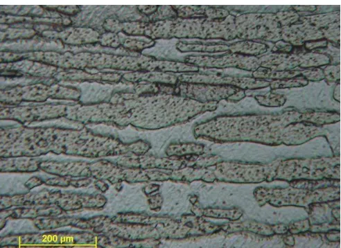
Fig. 2. Microstructure of the 2205 type duplex steel
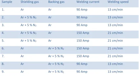
Available Online at www.ijpret.com 20 Table 2. Parameters of the welding experiments
Sample Shielding gas Backing gas Welding current Welding speed
1. Ar Ar 90 Amp 13 cm/min
2. Ar + 5 % N2 Ar 90 Amp 13 cm/min
3. Ar + 5 % N2 Ar 90 Amp 13 cm/min
4. Ar + 5 % N2 Ar 150 Amp 21 cm/min
5. Ar + 5 % N2 Ar 150 Amp 21 cm/min
6. Ar Ar + 5 % N2 150 Amp 21 cm/min
7. Ar Ar + 5 % N2 150 Amp 21 cm/min
8. Ar Ar + 5 % N2 90 Amp 13 cm/min
9. Ar Ar + 5 % N2 90 Amp 13 cm/min
Crown side
ATIG TIG
Flux
Welding direction Welding direction Welding direction
Root side ATIG
TIG
Fig. 3. Crown side and back side of the welded joint of the Sample 4.
2. CHARACTERISATION OF THE WELD POOL GEOMETRY
Available Online at www.ijpret.com 21 parameters were always used as bases and changing were made according to the actual examined factor. By the course of these experiments the answers for the problems of other determinant factors were attained. These results, which are detailed in the followings help substantially the application of the ATIG welding.
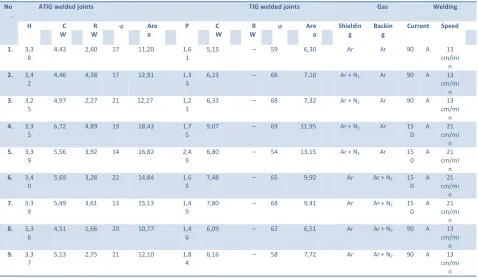
For characterization of the weld pool shape we measured the weld penetration, the width of weld bead and root and the cross section of weld. These characteristics change significantly in function of welding current, welding speed and the nitrogen content of gases. The characteristic measures of solidified weld pool can be seen in Fig. 4. The geometry of weld pool was characterized by measurement of characteristic measures of weld metal, namely width at crown and root side (CW, RW), maximal height (H), penetration (P), deflection angle from vertical axe (ϕ) and the total area of weld metal cross section.
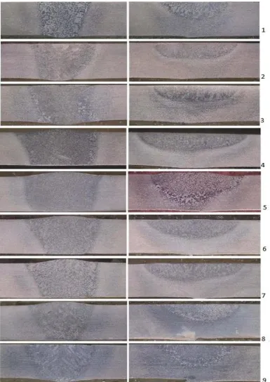
The weld pool geometry was investigated by optical microscopy. The macrographs of the weld cross section are presented in the Fig. 5. The pictures show clearly that the weld penetration at TIG-welded joint is much smaller then at ATIG-welded joints. The root is perfectly formed at ATIG-welded joints. Measured characteristics of weld metal are illustrated in Table 3.
Available Online at www.ijpret.com 22 Fig. 5. Cross sections of seams welded by ATIG welding (left) and TIG welding (right). The
Available Online at www.ijpret.com 23 Table 3. Measured values of the weld metal geometry in function of welding parameters (H,
CW, RW are in mm, ϕ is in degree, Area is in mm2).
No .
ATIG welded joints TIG welded joints Gas Welding
H C
W R W
ϕ Are
a
P C
W
R W
ϕ Are
a Shieldin g Backin g Current Speed 1. 3,3 8
4,43 2,60 17 11,20 1,6
1
5,15 – 59 6,30 Ar Ar 90 A 13
cm/mi n
2. 3,4
2
4,46 4,38 17 12,91 1,3
3
6,23 – 66 7,10 Ar + N2 Ar 90 A 13
cm/mi n
3. 3,2
5
4,97 2,27 21 12,27 1,2
1
6,33 – 68 7,32 Ar + N2 Ar 90 A 13
cm/mi n
4. 3,3
5
6,72 4,89 19 18,43 1,7
5
9,07 – 69 11,95 Ar + N2 Ar 15
0
A 21
cm/mi n
5. 3,3
9
5,56 3,92 14 16,82 2,4
9
6,80 – 54 13,15 Ar + N2 Ar 15
0
A 21
cm/mi n
6. 3,4
0
5,69 3,28 22 14,84 1,6
5
7,48 – 65 9,92 Ar Ar + N2 15
0
A 21
cm/mi n
7. 3,3
9
5,49 3,61 13 15,13 1,4
9
7,80 – 68 9,41 Ar Ar + N2 15
0
A 21
cm/mi n
8. 3,3
6
4,51 1,66 20 10,77 1,4
6
6,09 – 62 6,51 Ar Ar + N2 90 A 13
cm/mi n
9. 3,3
7
5,13 2,75 21 12,10 1,8
4
6,16 – 58 7,72 Ar Ar + N2 90 A 13
cm/mi n
3. DISCUSSION
Effect of the joint gap. It was considered that more the joint gap is closer to zero the better, but this is not realizable in practice. In industrial applications there is no possible to flatten the small geometrical defects, because of the productivity. The joints were made on V-form attached plates with zero gaps on one end and bigger on the other. This bigger gap was being got closer to the maximal allowable gap and finally the suitable gap size was found. It is ascertainable that if the maximum applicable gap does not exceed 0.7 mm for the 5 mm thick plates and 0.3 mm for the 3 mm thick plates then any welding insufficiency and inclusions will not occur. Simply there will not be enough base metal (because of the inaccurate joint preparation) to fill up the joint gap with molten metal.
Available Online at www.ijpret.com 24 acetone or ethanol absolute was found the most accurate for this aim. Suspension that is painted on the surface forms a thin, well-regulated, fast dryer, homogeneous and well adherer coating. By this applying method the regulating is reduced for proper mixing of suspension because the speed of painting must be sufficient. This assures that the accurate measure of flux shall be left on the joint’s surface after drying.
Sensitivity of ATIG welding for the quantity of flux. Does really the suspension applied by human produce a constant measure and homogeneity? During this experiment it was examined that whether the uncertainty of applying of flux (because of human chain-link) will fall into the interval that is proper for ATIG welding or not. As a result of this experiment it was stated that the changing of the suspension’s density by ± 50 % does not cause any detectable differences. It sounds well but do not forget the facts what measure belongs to this percentage. Because of the ± 50 % of the mentioned very small quantities the applying of fluxes suggested to be done by mechanized painter head.
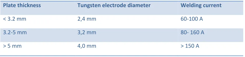
Choosing tungsten electrode. The higher heat load of tungsten (compared to TIG) probably comes from the higher reflected heat that is caused by the good insulator activating flux. The tungsten electrode has to wear this higher heat load. Realized these phenomena the recommendation, which are in the Table 3 has been worked out for choosing the suitable size of tungsten electrode for ATIG welding applications.
Table 3. Recommendation for choosing of tungsten electrode for ATIG welding of 2205 steels
Plate thickness Tungsten electrode diameter Welding current
< 3.2 mm 2,4 mm 60-100 A
3.2-5 mm 3,2 mm 80- 160 A
> 5 mm 4,0 mm > 150 A
Available Online at www.ijpret.com 25 This heat load depends on the amperage, which depends on the thickness. Finally, it is standable that the manual ATIG welding is applicable until 5 mm thickness. Comparison of TIG and ATIG welded joints. To compare correctly the two procedures proper plate thickness had to be found which was weldable by one root with both TIG and ATIG welding. Thickness of 3 millimeters was found the most suitable for this aim, because this size is the upper limit of the weldability (by one root) of TIG welding with acceptable productivity. The upper limit problem does not exist related to ATIG welding, because we do not know its upper limit of weld-ability (by one root). During experiments for austenitic stainless steels (before present work) the 8 mm plate thickness welding by one root butt-weld was attained. These joints were made by 220 A and welding speed of 8 cm/min.
5. CONCLUSIONS
The presented results show that the ATIG welding is applicable in industrial environments and it belongs to the high productivity welding procedures. Its application is suitable for mechanized welding of thick plates over 3 mm with one root (e.g. orbital welding of thick -walled pipes). More-over the possibility of manual applications cannot be precluded based on the manually applied experiments especially at lower thickness (for instance field welding of tanks with wall thickness of 3-5 mm). Increasing the competence of the ATIG process, the welding of much thicker of plates, pipes is possible with one pass. This fact, and the moderate price, thanks to the simple composition of the activating flux altogether makes this method economical.
The reduced heat input was shown also in the size of the heat-affected zone: the HAZ is narrower. The investigation of the sensibility for the root gap proved, that the ATIG welding can be applied not only with zero gap. According to our experiences the maximal gap can be 10 % of plate thick-ness. This fact makes the ATIG-welding applicable in the industry.
REFERENCES
1. A.G. SIMONIK, Svar. Proiz., (1974:3), p.52.
2. M. M. SAVITSKIJ and G.I. LESKOV, Avtom. Svarka, (1980:9), p.17
3. C.R. HEIPLE et al., Weld. Res. Suppl., (1985:6), p.159.
4. G. M. Oreper, T. W. Eagar and J. Szekely, Welding Journal, 62, (1983) p.307.
5. J.J. LOWKE, M. TANAKA and M. USHIO, J. Phys.D: Appl. Phys., 38, (2005) p.3438.
Available Online at www.ijpret.com 26 7. P.C.J. ANDERSON and R. WIKTOROWICZ, TWI report 549/1996
8. N. AMES, M. HOLMQUIST and M.Q. JOHNSON, Proc. Duplex 2000 Conf.
9. M.Q. JOHNSON and CH.M. FOUNTAIN, US Patent 6707005 (2004)
10.J. CORNU, TIG and related processes. IFS Publications Ltd., Bedford, UK, (1988)
11.J.J. LOWKE, M. TANAKA and M. USHIO, Austral. Weld. J., 47, (2002)
12.R. Badji, Mater. Charact., (2007) in press
13.S. SIRE, S. MARYA, C.R. Mecanique, 330, (2002) p.83.
14.S. SIRE, G. Rückert and S. MARYA, Matériaux 2002, Tours, CM08006.PDF
15.P.J. MODENESI, E.R. APOLINÁRIO and I.M. PEREIRA, J. Mater. Proc. Tech., 99 (2000) 260.
16.T. PASKELL, C. LUNDIN and H. CASTNER, Weld. J., 76, (1997) p.57