93
*Corresponding authorEmail address: [email protected]
An efficient finite difference time domain algorithm for band structure
calculations of Phononic crystal
M. Moradi and M. Bagheri Nouri *
Department of Mechanical Engineering, Isfahan University of Technology, Isfahan, 84156-83111, Iran
Article info: Abstract
In this paper, a new algorithm for studying elastic wave propagation in thephononiccrystals is presented. At first, the displacement-based forms of elastic wave equations are derived and then the forms are discretized using finite difference method. So the new algorithm is called the displacement-based finite difference time domain (DBFDTD). Three numerical examples are computed with this method and the results are compared with experimental measurements and the conventional FDTD method. Also, the computational cost of the new approach is compared with the conventional FDTD method. The comparison showed that the calculation time of the DBFDTD method is 37.5 percent less than that of the FDTD method. Received: 31/10/2015
Accepted: 08/03/2016 Online: 03/03/2017
Keywords:
Phononic crystal, Wave propagation, Finite difference time domain,
Displacement-based formulation.
1. Introduction
Phononic crystals have attracted a great deal of research in recent years. These inhomogeneous structures are the periodic arrangement of inclusions in an elastically different material. The frequency range in which elastic waves cannot propagate in any direction is called complete band gap. By realization of the complete band gap, these crystals can manage propagation of elastic waves in any direction [1,2]. Some applications of phononic crystals are acoustic filters and waveguides.
Theoretical and experimental studies on phononic crystals have been performed in several types of researches [3-6]. To analyze these composites numerically, several
researchers have used the plane wave expansion (PWE) method [7-10]. Despite the simplicity of PWE method, it encounters convergence problems when the phononic crystal has a large elastic mismatch. In this case, a great number of plane waves are required for convergence. Furthermore , the PWE method fails when the inclusion is a fluid or vacuum [11-12].
94
large elastic mismatch exists. It can deal with finite size structures and arbitrary shaped inclusions. In addition, it doesn't require any matrix calculations (explicit). In spite of these advantages, the FDTD method requires considerable computations. Therefore, it is necessary to optimize the conventional FDTD method.
Although Cao et al. [23] presented an appropriate initial condition to reduce the computational cost of the FDTD method, they used the same formulation of the conventional FDTD method. In this paper, a new algorithm for analysis of phononic crystals is presented. Against the conventional FDTD method, this approach combines equations of motion and constitute laws to derive displacement-based elastic wave equations. Then, these equations are discretized by finite difference method. We called it displacement-based finite difference time domain (DBFDTD) method. Comparing the DBFDTD formulas presented in the appendix with those of FDTD [11] reveals that the new algorithm requires less elementary arithmetical operations. Therefore computation cost of the new approach is less than the conventional FDTD method.
Three square arrangements, i.e., steel cylinders in water, circular vacuum holes in an aluminum matrix and steel cylinders in an epoxy host are considered. Band structures of elastic waves that propagate perpendicular to the cylinder axis are calculated. The results are compared with experimental measurements [4] and the conventional FDTD method. The computational cost of the new approach is compared with the conventional FDTD method.
Comparison of the DBFDTD results for computing the band structure of various phononic crystals with those of the conventional FDTD method and experimental measurements showed that the DBFDTD method can be used reliably to simulate phononic crystals. In addition, the computational cost of the DBFDTD approach is less than the FDTD method so that the calculation time can be reduced up to 37.5 percents. These features indicate the efficiency of the presented method for analyzing phononic crystals.
2.
FormulationFor simplicity, two-dimensional (2D) phononic crystals are considered. The formulation can be easily expanded to 3D crystals. The cylinders are aligned along the z-direction and are repeated infinitely in the XY plane. The equations of elastic wave can be written as:
.. ,
i ij j
u
ρ
=
σ
, (1),
ij C uijmn m n
σ
= , (2)where
ρ ρ
= ( , )x y andC x yijkl( , )are the density and elastic stiffness tensor of the structure, respectively. The summation convention over dummy indices is considered. Since propagation of the elastic wave in the XY plane is assumed, the displacement of the lattice and its stress tensor do not depend on z, i.e.,( , , )
i i
u u x y t
=
andσ
ij =σ
ij( , , )x y t .According to Bloch theorem, the periodic boundary condition can be written as:
( , ) exp(i ) ( , )
i i
u x +a t = k.a u x t , (3) ( , ) exp(i ) ( , )
ij t ij t
σ
x +a = k.aσ
x , (4)where x=( , )x y T.
a
and k are the latticevector and wave vector, respectively. Subscript i, j are tensor indices
.
To apply easily the periodic boundary condition,u
i andσ
ij are introduced as follows:( , ) exp( i ) ( , )
i i
u x t = −k.x u x t , (5) ( , ) exp( i ) ( , )
ij t ij t
σ
x = −k.xσ
x , (6)The periodic boundary condition can be rewrittenas:
( , ) ( , )
i i
u x +a t =u x t , (7)
( , ) ( , )
ij t ij t
σ
x +a =σ
x , (8)Substitution of Eq. (5-6) in Eq. (1-2) yields [11]:
..
,
i
i ij j j ij
u
k
95
,
( i )
ij Cijmn um n k un m
σ
= + , (10)Now these equations may be discretized and solved by the FDTD method. Suppose that the inclusion and host materials are isotropic. For the study of the mixed mode, in this case, the discretized form of Eq. (9) in a typical node (l,m) at time step n+1 can be rewritten as [11]:
, ; 1 , ; , ; 1 2 ,
1 1 1
1/2, ; 1/2, ; 1 11 1 11
, 1/2; , 1/2; 2 12 2 12
2 /
(
)
l m n l m n l m n l m
l m n l m n
l m n l m n
u u u t
K K
K K
ρ
σ
σ
σ
σ
+ −
+ + − −
+ + − −
= − + ∆
+
+ +
(11)
where
σ σ
11, 12 are components of stress tensor calculated from the constitutive Eq. (10); (l,m) defines a two-dimensional grid point and n stands for time step incremental number. The symbolsK
1+,K
1−,K
2+,K
2− are defined as:1
(
12) / (2 )
K
+= ∆ +
k x
∆
x
,
1
(
12) / (2 )
K
−=
k x
∆ −
∆
x
,2
(
22) / (2 )
K
+=
k y
∆ +
∆
y
,2
(
22) / (2 )
K
−=
k y
∆ −
∆
y
.
x
∆
and ∆y are grid spacing.k
1andk
2 are thex and y component of the wave vector, respectively. For example the discretized form of
σ
11is as follows:1/2, ; 1/2, 1, ; , ;
11 11 1 1 1 1
1/2, 1/2, 1/2;
12 2 2
1/2, 1/2,; 2 2
( )
( )
l m n l m l m n l m n
l m l m n
l m n
C K u K u
C K u
K u
σ
+ + + + −+ + + + − + −
= +
+ +
(12)
There are some equations similar to Eq. (11-12) which has been found in detail in Ref. [11]. To update x component of displacement at node (l, m), Eq. (11) shows that it is needed to evaluate components of stress tensor at four coordinates, .i.e. , 1/2, ;
11l m n
σ
+ , 1/2, ; 11l m nσ
− , , 1/2; 12l m nσ
+, , 1/2; 12l m n
σ
− . As Eq. (12) shows, computation of each of aforementioned stress componentsrequires considerable elementary arithmetical operations. To calculate band structure, fast Fourier transformation of displacement data are taken, therefore calculated stress components have not any direct contributions.
So conventional FDTD method requires computation of components of stress tensor which are only used for updating components of displacement. By derivation of displacement-based forms of elastic wave equations and discretization of resultant equations one can remove components of stress tensor from the updating equations. This leads to the efficient updating equations which require less elementary arithmetical operations and therefore less computational cost. This efficiency can be easily understood by comparison of Eq. (A.5-A.6) with Eq. (11-12). This comparison shows that Eq. (A.5-A.6) have about 44% less elementary arithmetical operations. The procedure of derivation of these updating equations is explained below.
For points beyond the interface of the inclusion and the host material, we have:
, ( , i , )
ij j Cijmn um nj k un m j
σ
= + (13)By Substitution of Eq. (10, 13) in Eq. (9), the displacement-based formulation of the elastic wave propagation in phononic crystals can be derived as:
..
, , ,
(
i
i
)
i ijmn m nj n m j j m n j n m
u C
u
k u
k u
k k u
ρ
=
+
+
−
(14)
96
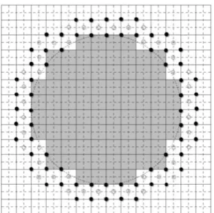
typical phononic crystal. In this figure, the solid and hollow circles indicate interfacial grid and half-grid points, respectively. As can be seen from Fig. 1, the four points surrounding each interfacial point may not be the same material. Also Fig. 1 shows that a few numbers of points are interfacial. To update the displacements of these points, Eqs. (9-10) should be used. To update the displacements of other ones, Eq. (14) is applied. So displacements of plenty of points can be updated by Eq. (14) which is more efficient than Eqs. (9-10).
Fig. 1. Discretized unit cell of a typical phononic crystal. The solid and hollow circles represent interfacial grid and half-grid points, respectively.
Now, finite difference method may be used to discretize the displacement-based Eq. (14) in both space and time domains. The discretized form of Eq. (14), which is called displacement-based finite difference time domain (DBFDTD), is given in the appendix. To discretize Eq. (14), all derivatives are replaced with central difference approximations. By applying the initial (pulse type) and periodic boundary conditions, resultant equations can be solved numerically to give the displacement of the non-interfacial grid points for a specified wave vector. For the interfacial grid and half-grid points, the discretized form of the Eq. (9-10) are used. To implement the DBFDTD method, the periodic boundary condition reduced to Eq. (7). Taking fast Fourier transformation of a sufficiently large number of displacement data for a given wave vector leads to the frequency spectrum. Peaks of obtained frequency spectrum indicate the position of eigenfrequencies.
3. Numerical examples
Consider propagation of the elastic wave in the XY plane. Therefore the displacement of the lattice and its stress tensor do not depend on z. With this assumption, there are two decoupled vibrational modes: mixed mode with the displacements in the XY plane and transverse mode with the displacement along the z direction. Explicitly, propagation of the mixed mode in the XY plane is studied. In numerical calculation, three different square arrangements are considered, i.e., steel rods in epoxy, vacuum holes in aluminum and steel rods in the water. To implement the DBFDTD scheme, a grid of
*
n n
(n=60-200) points in the unit cell was assumed. Numerical examples were calculated by a developed FORTRAN code based on parallel processing algorithm. The parallel code divides the calculation by wave vectors.3. 1. Steel in epoxy
As the first example, a 2D square steel/epoxy lattice was considered. The steel cylinders have a diameter d=6 mm and the lattice constant is a=8 mm. The density and elastic constants C11 and C44 of the steel are assumed to be 7900 kg/m3, 280.2 GPa and 82.9 GPa, respectively, and those for epoxy are 1180 kg/m3, 7.61 GPa and 1.59 GPa. Figure 2 shows the band structure obtained by DBFDTD calculation of the mixed mode. A grid of 60*60 points in the unit cell was assumed. The equations of motion were solved over 217 time steps with each time step
lasting for 15 ns. The dispersion relation shows a complete band gap that extends from 88 kHz to 210 kHz. The computed band gap compares very well with that of calculated by the FDTD method (90-204 kHz) [25].
The CPU time to calculate eigenfrequencies for a given wave vector is typically 30 min for the DBFDTD method and 48 min for the conventional FDTD method on an Intel core i7 CPU. The calculations were done for a grid of 60*60 points in the unit cell and 217 time steps.
97
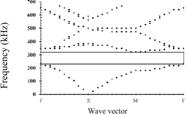
3. 2. Steel in waterFigure 3 presents the dispersion relations of the mixed mode calculated with the DBFDTD method for a 2D square steel/water lattice. The steel rods have a diameter d=2.5 mm and the lattice constant is a=3 mm. The density and longitudinal velocity of the water are assumed as 1000 kg/m3 and 1490 m/s, respectively. A grid of 60*60 points in the unit cell was considered. The equations of motion were solved over 217 time steps with each time step
lasting 2.4 ns.
Figure 3 shows a complete band gap extending from 231 kHz to 321 kHz. An experimental observation of the phononic crystal showed a complete band gap extending from 250 kHz to 325 kHz [4]. So the computed complete band gap and the experimental data are in good agreement.
Fig. 2. DBFDTD results (with a grid of 60*60 points in the unit cell) for the band structure of the mixed mode in a two-dimensional square arrangement of steel rods in the epoxy background. The diameter of cylinders is d=6 mm and the lattice constant is a=8 mm. The complete band gap is represented as the rectangular area.
Fig. 3. The band structure of the mixed mode in a two-dimensional square arrangement of steel rods in
water background. The diameter of cylinders and lattice constant are d=2.5 mm and a=3 mm, respectively. The DBFDTD method was implemented with a grid of 60*60 points in the unit cell. The complete band gap is showed as the rectangular area.
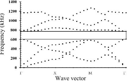
3.3 Vacuum holes in aluminum
In Fig. 4 the dispersion relations of the mixed mode calculated by DBFDTD method for 2D square vacuum/aluminum lattice is shown. The diameter of circular vacuum holes (d) and the lattice constant (a) are 2.5 and 3 mm, respectively. The density and elastic constants C11 and C44 of aluminum are assumed as 2700 kg/m3, 110.9 GPa and 26.1 GPa, respectively. A
grid of 200*200 points in the unit cell was assumed. The equations of motion were solved over 217 time steps with each time step lasting
for 0.83 ns. Figure 4 shows a complete band gap extending from 609 kHz to 772 kHz. The frequency range of the computed complete band gap can be given in terms of the reduced frequency (wa/vt) as 3.69-4.68, where w is the
angular frequency and vt is the shear velocity of
aluminum. The DBFDTD result for the band gap is in agreement with the result (3.8-4.8) obtained by the FDTD method [11].
4. Conclusions
A displacement-based finite difference time domain (DBFDTD) method was developed for simulating elastic wave propagation in the phononic crystals. At first, the displacement-based forms of elastic wave equations have been derived and then, this form has been discretized using finite difference method. The propagation of acoustic waves in three different 2D phononic crystals, i.e., a square arrangement of circular steel cylinders in the epoxy background, a square arrangement of circular steel cylinders in the water background and a square arrangement of circular vacuum holes in the aluminum background have been investigated by the new algorithm.
Comparison of the computed dispersion relations by the DBFDTD method with the experimental data and those obtained by the
Fre
qu
en
cy
(k
Hz)
Wave vector Wave vector
Fre
qu
en
cy
(k
98
conventional FDTD method proves the efficiency of the new algorithm for studying phononic crystals. Also, the computational cost of the DBFDTD method has been compared with that of the FDTD method which showed the calculation time of the DBFDTD method is 37.5 percents less than that of the FDTD method.
Fig. 4. The dispersion relations of the mixed mode in a two-dimensional square arrangement of circular vacuum holes in the aluminum background. The diameter of cylinders and lattice constant are d=2.5 mm and a=3 mm, respectively. The DBFDTD method was implemented with a grid of 200*200 points in the unit cell. The complete band gap is showed as the rectangular area.
Appendix
It is assumed that the inclusion and the host materials are isotropic. For the study of the mixed mode, in this case, Eq. (14) can be rewritten as:
..
2 2
1 1 11 2 44 1
1 2 12 44 2 1 11 1,1
1 12 44 2,2 2 44 1,2
2 12 44 2,1 11 1,11
44 1,22 12 44 2,12
( )
( ) 2i
i ( ) 2i
i ( )
( ) ,
u k C k C u
k k C C u k C u
k C C u k C u
k C C u C u
C u C C u
ρ
= − +− + +
+ + +
+ + +
+ + +
(
A.1
)..
2 2
2 1 44 2 11 2
1 2 12 44 1 2 11 2,2
2 12 44 1,1 1 44 2,1
1 12 44 1,2 11 2,22
12 44 1,12 44 2,11
( )
( ) 2i
i ( ) 2i
i ( )
( ) .
u k C k C u
k k C C u k C u
k C C u k C u
k C C u C u
C C u C u
ρ
= − +− + +
+ + +
+ + +
+ + +
(
A.2
)For a suitable representation of discretized form of the above equations, the following coefficients are defined:
, 2 , 2 ,
1 1 11 2 44
, , 2
2 11
, , 2
3 44
, ,
4 1 11
, ,
5 2 44
, , ,
6 1 2 12 44
, , ,
7 1 12 44
, , ,
8 2 12 44
, , ,
9 12 44
/
/
i /
i /
(
) / 4
i(
) / (2 )
i(
) / (2 )
(
l m l m l m
l m l m
l m l m
l m l m
l m l m
l m l m l m
l m l m l m
l m l m l m
l m l m l
k C
k C
C
x
C
y
k C
x
k C
y
k k C
C
k C
C
y
k C
C
x
C
C
α
α
α
α
α
α
α
α
α
=
+
=
∆
=
∆
=
∆
=
∆
= −
+
=
+
∆
=
+
∆
=
+
1/2, 1/2 2 1/2, 1/2 2 1/2, 1/2
10 1 44 2 11
1/2, 1/2 1/2, 1/2 2
11 44
1/2, 1/2 1/2, 1/2 2
12 11
1/2, 1/2 1/2, 1/2
13 1 44
) / (
)
/
/
i /
ml m l m l m
l m l m
l m l m
l m l m
x y
k C
k C
C
x
C
y
k C
x
α
α
α
α
+ + + + + + + + + + + + + + + + + +∆ ∆
=
+
=
∆
=
∆
=
∆
1/2, 1/2 1/2, 1/2
14 2 11
1/2, 1/2 1/2, 1/2 1/2, 1/2
15 1 2 12 44
1/2, 1/2 1/2, 1/2 1/2, 1/2
16 2 12 44
1/2, 1/2 1/2, 1/2 1/2, 1/2
17 1 12 44
1
i /
(
) / 4
i(
)
/ (2 )
i(
)
/ (2 )
l m l m
l m l m l m
l m l m l m
l m l m l m
k C
y
k k C
C
k C
C
x
k C
C
y
α
α
α
α
α
+ + + + + + + + + + + + + + + + + + + + + +=
∆
= −
+
=
+
∆
=
+
∆
1/2, 1/2 1/2, 1/2 1/2, 1/2
8
(
12 44)
/ (
)
l m
C
l mC
l mx y
+ +
=
+ ++
+ +∆ ∆
(
A.3
)99
, , , ,
1 1 2 3
, , ,
2 4 2
, , ,
3 4 2
, , ,
4 3 5
, , ,
5 3 5
, , , , ,
6 6 7 8 9
, , , , ,
7 6 7 8 9
, , , , ,
8 6 7 8 9
, , ,
9 6 7
2 2
l m l m l m l m
l m l m l m
l m l m l m
l m l m l m
l m l m l m
l m l m l m l m l m
l m l m l m l m l m
l m l m l m l m l m
l m l m l m
β α α α
β α α
β α α
β α α
β α α
β α α α α
β α α α α
β α α α α
β α α
= − − − = + = − + = + = − = + + + = − + − = + − − = − − , , 8 9
1/2, 1/2 1/2, 1/2 1/2, 1/2
1 10 11
1/2, 1/2 12
1/2, 1/2 1/2, 1/2 1/2, 1/2
2 11 13
1/2, 1/2 1/2, 1/2 1/2, 1/2
3 11 13
1/2, 1/2 1/2, 1/2 1/2, 1/
4 12 14
2 2
l m l m
l m l m l m
l m
l m l m l m
l m l m l m
l m l m l m
α α
γ α α
α
γ α α
γ α α
γ α α
+ + + + + + + + + + + + + + + + + + + + + + + + + + + = − − − = + = −
= + 2
1/2, 1/2 1/2, 1/2 1/2, 1/2
5 12 14
1/2, 1/2 1/2, 1/2 1/2, 1/2
6 15 16
1/2, 1/2 1/2, 1/2
17 18
1/2, 1/2 1/2, 1/2 1/2, 1/2
7 15 16
1/2, 1/2 1/2, 1/2
17 18
1/2, 8
l m l m l m
l m l m l m
l m l m
l m l m l m
l m l m
l m
γ α α
γ α α
α α
γ α α
α α γ + + + + + + + + + + + + + + + + + + + + + + + + + + + + = − = + + + = − + −
1/2 1/2, 1/2 1/2, 1/2
15 16
1/2, 1/2 1/2, 1/2
17 18
1/2, 1/2 1/2, 1/2 1/2, 1/2
9 15 16
1/2, 1/2 1/2, 1/2
17 18
l m l m
l m l m
l m l m l m
l m l m
α α
α α
γ α α
α α + + + + + + + + + + + + + + + + + + = + − − = − − +
(
A.4
)Coefficients introduced by Eq. (A.3- A.4) may be calculated before the time evolution loop of the DBFDTD method and stored in appropriate matrixes. Then it is not required to calculate them in each time step. Discretizing of Eq. (A.1) using the finite difference method leads to:
, ; 1 , ; , ; 1
1 1 1
2 ,
2 /
l m n l m n l m n
l m
u u u
t
ρ
+ = − −
+ ∆ ×Σ (
A.5
)where
:
, , ; , 1, ;
1 1 2 1
, 1, ; , , 1;
3 1 4 1
, , 1; , 1/2, 1/2;
5 1 6 2
, 1/2, 1/2; , 1/2, 1/2;
7 2 8 2
, 1/2, 1/2; 9 2
l m l m n l m l m n
l m l m n l m l m n
l m l m n l m l m n
l m l m n l m l m n
l m l m n
u u u u u u u u u
β
β
β
β
β
β
β
β
β
+ − + − + + + − − + − −Σ = × + ×
+ × + ×
+ × + ×
+ × + ×
+ ×
(
A.6
)Discretized form of Eq. (A.2) can be expressed as:
1/2, 1/2; 1 1/2, 1/2; 1/2, 1/2; 1
2 2 2
2 1/2, 1/2
2 /
l m n l m n l m n
l m
u u u
t
ρ
χ
+ + + + + + + − + + = − + ∆ ×
,
(A.7)
where:
1/2, 1/2 1/2, 1/2; 1/2, 1/2 1/2, 3/2;
1 2 2 2
1/2, 1/2 1/2, 1/2; 1/2, 1/2 3/2, 1/2;
3 2 4 2
1/2, 1/2 1/2, 1/2; 1/2, 1/2 1, 1;
5 2 6 1
1/2, 1/2 7
l m l m n l m l m n
l m l m n l m l m n
l m l m n l m l m n
l m
u u
u u
u u
u
χ γ γ
γ γ γ γ γ + + + + + + + + + + + − + + + + + + − + + + + + + + = × + × + × + × + × + ×
+ × 1, ; 1/2, 1/2 , 1;
1 8 1
1/2, 1/2 , ;
9 1
l m n l m l m n
l m l m n
u u γ γ + + + + + + + × + ×
(A.8)
References[1] M. S. Kushwaha, P. Halevi, L. Dobrzynski, and B. Djafari-Rouhani, “Acoustic band structure of periodic elastic composites”, Phys. Rev. Lett., Vol. 71, No. 13, pp. 2022-2025, (1993). [2] R. Martinez-Sala, J. Sancho, J. V.
Sanchez, V. Gomez, J. Llinares, and F. Meseguer, “Sound attenuation by sculpture”, Nature., Vol. 378, No. 6554, pp. 241-241, (1995).
[3] F. R. Montero de Espinosa, E. Jime´nez, and M. Torres, “Ultrasonic Band Gap in a Periodic Two-Dimensional Composite”, Phys. Rev. Lett., Vol. 80, No. 6, pp. 1208-1211, (1998).
100
ultrasonic crystal”, IEEE Ultrasonics Symposium, pp. 377-380, (2003).
[5] Y. Pennec, B. Djafari-Rouhani, J. O. Vasseur, A. Khelif, and P. A. Deymier, “Tunable filtering and demultiplexing in phononic crystals with hollow cylinders”, Phys. Rev. E., Vol. 69, 046608, (2004). [6] W. Liu, J. W. Chen, and X. Y. Su, “Local
resonance phononic band gaps in modified two-dimensional lattice materials”, Acta Mech. Sin., Vol. 28, pp. 659-669, (2012).
[7] M. Kafesaki, M. M. Sigalas, and N. García, “Frequency Modulation in the Transmittivity of Wave Guides in Elastic-Wave Band-Gap Materials”, Phys. Rev. Lett., Vol. 85, No. 19, pp. 4044-4047, (2000).
[8] A. Khelif, B. Djafari-Rouhani, J. O. Vasseur, and P. A. Deymier, “Transmission and dispersion relations of perfect and defect-containing waveguide structures in phononic band gap materials”, Phys. Rev. B., Vol. 68, No. 2, 024302, (2003).
[9] Y. Yao, Z. Hou, and Y. Liu, “The two-dimensional phononic band gaps tuned by the position of the additional rod”, Phys Let. A., Vol. 362, No. 5-6, pp. 494-499, (2007).
[10] B. Wu, R. Wei, H. Zhao, and C. He, “Phononic Band Gaps in Two-Dimensional Hybrid Triangular Lattice”, Acta Mech. Solida Sin., Vol. 23, No. 3, pp. 255-259, (2010).
[11] Y. Tanaka, Y. Tomoyasu, and S. Tamura, “Band structure of acoustic waves in phononic lattices: Two-dimensional composites with large acoustic mismatch”, Phys. Rev. B., Vol. 62, No. 11, pp. 7387-7392, (2000). [12] P. Hsieh, T. Wu, and J. Sun,
“Three-Dimensional Phononic Band Gap Calculations Using the FDTD Method and a PC Cluster System”, Ieee T. Ultrason. Ferr., Vol. 53, No. 1, pp. 148-158, (2006).
[13] D. García-Pablos, M. Sigalas, F. R. Montero de Espinosa, M. Torres, M. Kafesaki, and N. García, “Theory and
Experiments on Elastic Band Gaps”, Phys. Rev. Lett., Vol. 84, No. 19, pp. 4349 -4352, (2000).
[14] A. Khelif, P. A. Deymier, B. Djafari-Rouhani, J. O. Vasseur, and L. Dobrzynski, “Two-dimensional phononic crystal with tunable narrow pass band: Application to a waveguide with selective frequency”, J. Appl. Phys., Vol. 94, No. 3, pp. 1308-1311, (2003).
[15] J. H. Sun, and T. T. Wu, “Analyses of mode coupling in joined parallel phononic crystal waveguides”, Phys. Rev. B., Vol. 71, 174303, (2005).
[16] Y. Pennec, B. Djafari-Rouhani, H. Larabi, J. Vasseur, and A. C. Hladky-Hennion, “Phononic crystals and manipulation of sound”, Phys. Status Solidi C., Vol. 6, No. 9, pp. 2080-2085, (2009).
[17] H. F. Gao, T. Matsumoto, T. Takahashi, and H. Isakari, “Analysis of Band Structure for 2D Acoustic Phononic Structure by BEM and the Block SS Method”, CMES-Comp. Model. Eng., Vol. 90, No. 4, pp. 283-301, (2013). [18] M. Kafesaki, and E. N. Economou,
“Multiple-scattering theory for three dimensional periodic acoustic composites”, Phy. Rev. B., Vol. 60, No.17, 11993, (1999).
[19] Z. Z. Yan, and Y. S. Wang, “Wavelet-based method for calculating elastic band gaps of two-dimensional phononic crystals”, J. Comput. Phys., Vol. 74, 224303, (2006).
[20] B. Djafari-Rouhani, J. O. Vasseur, A. C. Hladky-Hennion, P. Deymier, F. Duval, B. Dubus, and Y. Pennec, “Absolute band gaps and waveguiding in free standing and supported phononic crystal slabs”, Photonic Nanostruct., Vol. 6, No. 1, pp. 32-37, (2008).
101
[22] M. Liu, P. Li, Y. Zhong, and J. Xiang,“Research on the band gap characteristics of two-dimensional phononic crystals micro-cavity with local resonant structure”, Shock. Vib., Vol. 2015, 239832, (2015).
[23] Y. Cao, Z. Hou, and Y. Liu, “Finite difference time domain method for band-structure calculations of two-dimensional
phononic crystals”, Solid State Commun., Vol. 132, No. 8, pp. 539-543, (2004). [24] A. Taflove, Advances in Computational
Electrodynamics, Artech House, London, (1999).
[25] T. T. Wu, J. H. Sun, “4G-3 Guided Surface Acoustic Waves in Phononic Crystal Waveguides”, IEEE Ultrasonics Symposium, pp. 673-676, (2006).
How to cite this paper:
M. Moradi and M. Bagheri Nouri, “An efficient finite difference time domain algorithm for band structure calculations of Phononic crystal”, Journal of Computational and Applied Research in Mechanical Engineering, Vol. 6. No. 2, pp. 93-101
DOI: 10.22061/jcarme.2017.60