A Model for Scuffing Prediction
Enrico Ciulli1,* - Ida Bartilotta1 - Alessandro Polacco2 - Salvatore Manconi3 - Dagoberto Vela1 - Francesco Saverio Guerrieri Paleotti1
1 University of Pisa, Dept. of Mechanical, Nuclear, and Production Engineering, Italy 2 Avio Propulsione aerospaziale S.p.A., Italy
3 AM Testing – c/o Lab. Scalbatraio, Italy
A correct prediction of scuffing failures is not easy. Several models have been developed by a number of authors but none can be applied with a certain degree of reliability in every conditions.
In this work a simplified model for scuffing prediction is proposed. The model takes into account the presence of various lubrication regimes during the machine running.
Experimental tests are being carried out at Pisa University in order to validate the model, under a cooperation agreement between AVIO Propulsione Aerospaziale S.p.A. and AM testing s.r.l.. The procedures used and first results are presented.
© 2010 Journal of Mechanical Engineering. All rights reserved.
Keywords: scuffing, friction, gear, Stribeck curves, thermal effects, non-conformal contacts
0 INTRODUCTION
Scuffing is a degenerative form of adhesive wear influenced by a great number of quantities. Working conditions (load, rolling and sliding speeds, oil temperature), materials, lubricant and additives characteristics, bodies’ surface characteristics (roughness and topography, surface treatments and coatings) and geometry of the lubricated contact are some of the most important factors influencing scuffing. Therefore, experimental works are of fundamental importance in order to understand how to avoid scuffing risk in machines and also to calibrate models for scuffing predictions that can reduce the long ad expensive tests.
Two main kinds of experimental apparata have generally been used: rigs using real components and rigs simulating the real contacts. For instance, tests on gears, often using the standardised FZG test low speed rig [1] to [3], on pistons [4] and [5] and on cams [6] and [7] have been carried out. In this case, real conditions of the machine components are better simulated, but it is more difficult to make detailed measurements of several quantities, such as local temperature, pressure and film thickness. Simulating rigs allow easier measurements, but some aspects of the real contacts can be lost. Several basic tribological test rigs for simulating the real contacts can be found in literature such as, for instance, ball-on-disc [8], four-ball [9] and discs [10] machines. Usually tests are carried out at constant speed by
increasing the load continuously [8] [9] or with steps [10] until a sudden increasing of friction and/or temperature is recorded. This transition is usually related to the scuffing arising.
A correct prediction of scuffing is not easy. Several models, based on energy or on temperature criteria, have been developed by a number of researchers, but none can be applied with a certain degree of reliability in every conditions. Some constants present in the models are usually calibrated using experimental results. Therefore their validity is often limited only to contacts similar to the ones investigated.
Some damage models use quite complex analytical/numerical solutions of the thermo-elastohydrodynamic model for non-conformal contacts. This calculation can be extremely time-consuming and it is difficult to combine it with other equations, such as the ones that describe lubricant behaviour.
Other models calculate energy losses using empirical formulas to evaluate the friction coefficient. However, these formulas usually do not consider the arising of different lubrication regimes, related to various film thickness during the machine running.
the original method requires a full numerical solution of the thermo-elastohydrodynamic equations, the proposed model uses only formulas that can more easily modified. Thus, the model should also be used for other kinds of gears and contacts using proper calibration of the constants based on experimental results. Some examples of the first experimental results obtained with a new gear test rig are also reported.
This study is a part of a larger research on gear characterization made jointly by the Department of Mechanical, Nuclear, and Production Engineering of the University of Pisa (DIMNP), AVIO Propulsione Aerospaziale S.p.A. and AM Testing s.r.l.
1 THE MODEL
Some formulas are used for a simple but comprehensive estimation of the friction coefficient, in order to take into account the transition from boundary to mixed and from mixed to full fluid lubrication conditions, as well as the presence of thermal effects. The constants that appear in the model are based on experimental data taken from literature, or obtained using an experimental apparatus for film thickness and friction measurements developed by Pisa University and briefly described, for instance, in [11] and [12].
A scuffing parameter [3] based on the ratio between the actual Friction Power Intensity and its limiting value (estimated from a critical temperature of the used lubricant and from the thermal characteristics of the contacting bodies) is used for scuffing prediction.
2.1 Friction Coefficient
The friction coefficient, fa, is evaluated
from boundary to full-film lubrication conditions by using a load sharing function g(Λ). g(Λ) is the portion of load supported by the full film contact and Λ is the ratio between the central film thickness and the surface roughness of the contacting bodies. According to [13], the following formula can be used:
1.2
( ) 1 ( )
a c b
f f g f g (1) where fc is the friction coefficient related to
hydrodynamic (full fluid) lubrication and fb is the
boundary friction coefficient. Several formulas
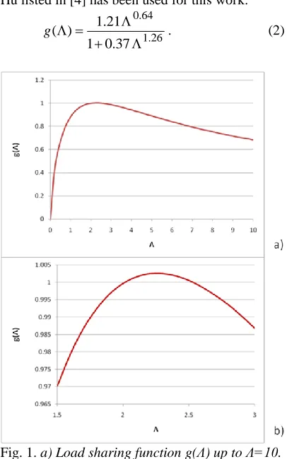
can be used to evaluate g(Λ). The one of Zhu and Hu listed in [4] has been used for this work:
0.64 1.26
1.21 ( )
1 0.37
g
. (2)
Fig. 1. a) Load sharing function g(Λ) up to Λ=10. b) Zoom of load sharing factor between Λ=1.5
and Λ=3
As shown in Fig. 1, the value of g(Λ) becomes greater than one for Λ = 2 and then rapidly decreases. For this reason g(Λ) is set to 1 for Λ > 2.
fb is usually considered constant (0.08 to
0.1 are typical values), while the determination of fc includes several aspects, such as the ones
related to the model used for the lubricant. A mean value of fc has been evaluated by dividing
the shear stress, τ, by the mean contact pressure, pm. For elliptical non-conformal contacts, such as
the ones occurring between crowned gear teeth, the mean contact pressure, pm, can be estimated as
two thirds of the Hertzian pressure pH:
H
H p
p p
f m c
2 3 3
/
2
. (3)
e L
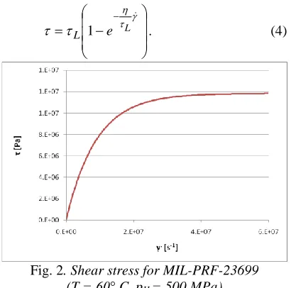
L 1 . (4)
Fig. 2. Shear stress for MIL-PRF-23699 (T = 60° C, pH = 500 MPa)
τL is the limiting shear stress, η is the
dynamic viscosity and is the shear strain rate. Formulas for τL and η can be obtained in literature
as a function of both temperature and pressure. The ones chosen for the neopentyl polyol ester base lubricant MIL-PRF-23699 are listed in the appendix. An example of shear stress trend for this lubricant, that has been used for some experimental tests described later in this paper, is shown in Fig. 2.
As a first approximation, can be evaluated as the ratio of the difference between the velocities of the two contacting bodies, Δu = u2 - u1, and the central film thickness hc.
Said u = (u2 + u1) / 2 the rolling velocity and S=Δu/u the slide-to-roll ratio, fc can be
evaluated by combining Eqs. (3) and (4):
hc
u S L
c e
p f
H
L
1 2 3
. (5)
The central film thickness, hc, can be
calculated with formulas for isothermal lubricated contacts. Isoviscous-elastic and elastohydro-dynamic regimes are of particular interest. In order to take into account the film thickness reduction due to thermal effects, one of the equations available in literature has been used. The formulas used are listed in the appendix.
The calculated film thickness is also used for the evaluation of Λ.
A preliminary comparison of the results obtained between Eq. (1) and experimental data,
has shown that Eq. (1) is not suitable for taking into account the friction reduction that can occur by increasing the slide-to-roll ratio S, as found for instance in [12]. A more correct evaluation of the friction coefficient, f, has been obtained multiplying fa (E q.(1)) by a thermal correction
function, c, based on the product η0pHu and on S
(0 is the atmospheric pressure viscosity). The function is related to the traction behaviour of the lubricant used. The results listed in this work are related to MIL-PRF-23699 lubricant. The experimental results of [14] have been used, particularly the friction coefficient values of the traction curves shown in Fig. 4 (S/2 is on the abscissa).
Fig. 3. Experimental traction curves for MIL-PRF-23699 lubricant. From [5]
The maximum value of friction coefficient, as shown in Fig. 4, depends on lubricant temperature (and therefore on viscosity η0), pressure pH and velocity u. Due to the fact
that the parameter η0pHu is related to the friction
power losses, a function of this quantity has been searched for. As a first attempt, it has been found that the maximum of each curve occurs when Sm= 0.01[η0 pH u]-3/2 and the thermal correction
function, to be used for S > Sm, is:
0.088ln(0 ) 0.220
0.28 ln( ) 0.39 p uH
H
c
p u S (6) For S < Sm, c = 1.
2.2 Scuffing Criterion
Friction Power Intensity, f pH Δu , along the line
of action. The maximum value between the arc of approach and the arc of recess is evaluated and it is compared with a quantity depending on a thermal conductivity, C, and on the difference between a critical lubricant temperature, Tcr,and
the oil bath temperature, T0. The scuffing risk increases by increasing this maximum value. In [3] the friction coefficient, f, is evaluated by using a formula purposely developed for FZG testing conditions. The use of the formula developed in this work could extend the applicability of the criterion to different conditions and different kind of gears. In this work, the friction coefficient is evaluated by multiplying Eq. (1) and (6), f = cfa.
According to [3], a scuffing parameter SP is calculated:
0
H H
2 max f p , f p
pitch B
b b
A pitch
cr
u r d u r d
SP
C T T
.(7)
The first integral is evaluated from the beginning of the arc of approach, θA, to the pitch point, θpitch, while the second integral is evaluated from the pitch point to the end of the arc of recess, θA; rb is the base radius of gear.
The criterion has been implemented in a software that use, as input, the load distribution from LDP (Load Distribution Program [15]). Tcr =
126° C has been use for MIL-PRF-23699. According to [3], if SP > 1 scuffing occurs, if SP < 0.7 scuffing does not occur.
2 EXPERIMENTAL WORK
In order to validate and optimize the analytical model, scuffing tests are being carried out at Pisa University.
The research program has been planned using Design of Experiment (DoE) technique. The parameters considered are:
• material;
• surface finishing; • pressure angle; • peripheral speed; • lubricant temperature.
Each parameter is tested at two levels. In particular, peripheral speed and lubricant temperature must be defined using specific tests (search tests) that are currently carried out.
Purposely designed gears are used in the experimental campaign: the main characteristics of test gears are listed in Table 1:
Table 1. Main characteristic of test gears Number of teeth 28
Centre distance 140 mm Pressure angle 20° (right flank)
25° (left flank)
Material AMS 6265
AMS6308
Surface finishing As Ground (Ra: 0.4 μm) REM (Ra: 0.1 μm)
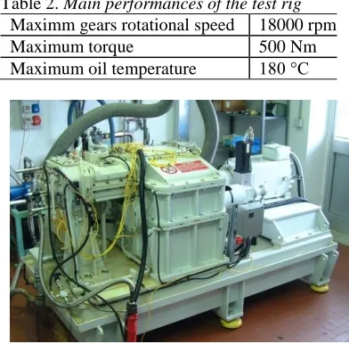
The experimental apparatus is composed by a re-circulating power gear test rig [16], purposely designed for aerospace gear testing [17] (Fig. 2). The rig, operating at the Gear Research Centre (Centro Ricerca sulle Trasmissioni Meccaniche, CRTM) located in the "Scalbatraio" test site of DIMNP, can achieve the following performances:
Table 2. Main performances of the test rig Maximm gears rotational speed 18000 rpm
Maximum torque 500 Nm
Maximum oil temperature 180 °C
Fig. 4. Test rig for the characterization of aerospace gears
The gears input lubricant is a synthetic oil for aerospace applications, defined by the MIL-PRF-23699 specification. In mesh lubrication is used.
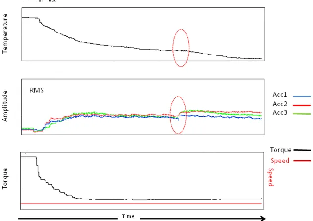
high frequency accelerometers, and complex diagnostic techniques are used in order to detect failures. In particular, the damage can be detected by the increase of out of mesh temperature and a change in RMS value (Fig. 6).
Fig. 7 shows the calculated friction coefficient f at the load step when failure occurs. In this condition, scuffing parameter SP predicts failure (2.3).
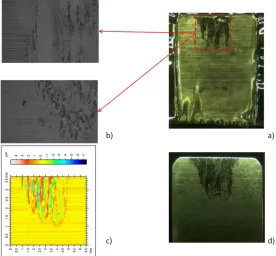
The study of the surface gears teeth damage is performed by using 3D roughness acquisition, stereo and electron microscope analysis, replicas and metallographic analysis (Fig. 8).
Fig. 5. Example of scuffing test. The red line indicates gears running-in
Fig. 6. Scuffing failure a) Increase of out of mesh temperature; b) Change in RMS value; c) Test conditions
Fig. 8. a) Replica;b) Metallographic microscope analysis of replica;c) 3D roughness analysis; d)Stereo microscope appearence of scuffing
3 CONCLUSION AND FUTURE DEVELOPMENTS
The model proposed in this paper can extend the scuffing criterion proposed in [3] to different kind of gears (not only FZG gears) and to different working conditions, thanks to a more general evaluation of the friction coefficient and to the use of formulas instead of solving the equations of the thermo-elastohydrodynamic problem. The model has been implemented in a software that currently uses LDP load distribution in order to evaluate the scuffing risk.
Some of the formulas and constants present in the model will be optimised and validated by using the experimental results of an extensive tests campaign carried out at Pisa University. Particularly, one of the main goal of the experimental campaign is to evaluate the constants of the model, in particular C and Tcrof
Eq. (7).
Some first experimental results agree with the numerical ones, despite the use of some not-optimised constant values taken for the literature. It is obviously suitable to wait for the end of the experimental campaign in order to validate the model.
4 APPENDIX
For the lubricant MIL-PRF-23699, the limiting shear stress has been evaluated as a function of temperature, T, and pressure, p, with the formula [14]:
0
2 1 1
3
0
a
p p
T T
L H L
L L e
with the reference values τL0 = 7.5927x10⁶ Pa,
αL = 1.3338x10⁻⁹ Pa-1, pa atmospheric pressure,
βL = 0, T0 = 80° C.
Table 3. Formulas for central film thickness evaluation Lubrication regime hc
Isoviscous-elastic
k
x e
F E
R
u 0.28
213 . 0 447 . 0 766 . 0 66 . 0 66 . 0
0 1 0.72
' 15 .
11
Elastohydrodynamic
k
x
e F
E
R
u 0.73
063 . 0 087 . 0 446 . 0 68 . 0 53 . 0 68 . 0 0 61 . 0 1 ' 61 .
3
0
01 135
5 0 6.3110
S T
G
pH pa
e 3 2 0
with S0 = 1.084, G0 = 3.45 and
) log( 10 485 . 6 10 609 .
2 8 9
0
.
The central film thickness hc has been
evaluated using the formulas reported in Table 3. Rx is the equivalent radius along the
entraining motion direction, E’ the equivalent elastic modulus, F the load and k the ellipticity ratio. The calculated film thickness value has been corrected by multiply it by a reduction factor
0.83 0.64
1
1 0.1 (1 8.33S )L
with 2 0u
L ,
0 0 0 135 67 . 9 ) ln( T S
and
κ = 0.1678 – 0.0001094(T0 + 273.1) thermal conductivity.
5 ACKNOWLEDGEMENTS
The authors would like to thank Jonny Harianto of Gears and Power Transmission Research Laboratory of Ohio State Univerisity for the support on LDP program.
6 REFERENCES
[1] Castro, J., Seabra, J. (1998). Scuffing and lubricant film breakdown in FZG gears part I. Analytical and experimental approach, Wear, vol. 215, p. 104-113.
[2] Höhn, B. R., Michaelis, K. (2004). Influence of oil temperature on gear failures, Tribology International, vol. 37, p. 103-109.
[3] Castro, J., Sottomayor, A., Seabra, J. (2005). Experimental and analytical scuffing criteria for FZG gears, Life Cycle Tribology, D. Dowson et al. (Eds.), Elsevier, p. 651-661.
[4] Zhang, C., Cheng, H. S., Wang, Q. J. (2004). Scuffing behaviour of piston-pin/bore bearing in mixed lubrication – Part II: scuffing mechanisms and failure criterion, Tribology Transactions, vol. 47, p. 149-156. [5] Ye, Z., Zhang, C., Wang, Y., Cheng, H. S.,
Tung, S., Wang, Q. J., He, X. (2004). An experimental investigation of piston skirt scuffing: a piston scuffing apparatus, experiments, and scuffing mechanism analyses, Wear, vol. 257, p. 8-31.
[6] Lewis, R., Dwyer-Joyce, R. S. (2002). Wear of diesel engine inlet valves and seat insert, Proc. Instn. Mech. Engrs, 216, Part D, J. of Automobile Engineering, p. 205-216. [7] Lindhom, P., Svahn, F. (2006). Study of
thickness of sputtered-carbon coating for low friction valve lifters, Wear, vol. 261, p. 241-250.
[8] Andersson, S., Salas-Russo, E. (1994). The influence of surface roughness and oil viscosity on the transition in mixed lubricated sliding steel contacts, Wear, vol. 174, no. 1-2, p. 71-79.
[9] Szczerek, M., Tuszynski, W. (2002). A method for testing lubricants under conditions of scuffing. Part I. Presentation of the method, Tribotest, p. 273-284.
[10] Patching, M. J., Kweh, C. C., Evans, H. P., Snidle, R. W. (1995). Conditions for scuffing failure of ground and superfinished steel disks at high sliding speeds using a gas turbine engine oil, Trans. of the ASME, vol. 117, p. 482-489.
[11] Ciulli, E., Lorenzetti, M., Stadler, K. (2008). Investigation on Material and Dimension Effects in Elastohydrodynamic Lubricated Point Contacts, Proceedings of the 16th
International Colloquium Tribology, Technische Akademie Esslingen, Germany, on CD.
friction coefficient and film thickness of EHD point contacts under steady state and transient conditions, Trib. Int., vol. 42, no. 4, p. 526-534.
[13] Castro, J., Campos, A., Sottomayor, A., Seabra, J. (2005). Friction Coefficient between Gear Teeth in Mixed Film Lubrication, D. Dowson et al. (Eds.), Life Cycle Tribology,Elsevier, p. 525-533. [14] Sottomayor, A., Campos, A., Seabra, J.,
Flamand, L., Nelias, D. (2004). Experimental Evaluation and Numerical Simulation of MIL-L-23699 Traction Curves, G. Dalmaz et al. (Eds.), Transient Processes in Tribology, Elsevier, p. 795-806.
[15] http://gearlab1.eng.ohio-state.edu/software.htm [16] Andrei, G.L., Manconi, S., Manfredi, E., Vitali, M., 2001, Attrezzature per prove su ingranaggi ad alte prestazioni, XXX Convegno Nazionale dell'Associazione Italiana per l'Analisi delle Sollecitazioni (AIAS2001), vol. 1, p. 127-