33
Available online at www.ijiere.com
International Journal of Innovative and Emerging
Research in Engineering
e-ISSN: 2394 – 3343 p-ISSN: 2394 – 5494
EFFECT OF SPEED, FEED AND DEPTH OF CUT ON
SURFACE ROUGHNESS OF SS304 MATERIAL
Motgi Rakesh S.1
a, Javed Dhalait G. 2
b, Narote Bhupsh E. 3
c1a, Lecturer, Mechanical Engineering Department, A. G. Patil Polytechnic Institute, Solapur, India. 2b, Lecturer, Mechanical Engineering Department, A. G. Patil Polytechnic Institute, Solapur, India. 3c, Lecturer, Mechanical Engineering Department, A. G. Patil Polytechnic Institute, Solapur, India.
ABSTRACT
Machining is one of the traditional process for precise shaping of components in the manufacturing industry. It is estimated that 15% of the value of all mechanical components manufactured worldwide are derived from machining operations. Hence it becomes very important to maintain surface finish along with mass production rate. In proposed work effect of speed, feed and depth of cut is taken into consideration during dry orthogonal turning of SS 304 material. This paper demonstrates effect of all said parameter on surface finish and difference between values of surface finish obtained through experimentation and theoretical calculation. Results obtained during work shows that a better theoretical relation can be build for finding surface finish.
Keywords: Orthogonal cutting, Turning, Speed, Feed, Depth of Cut, Nose Radius, Surface Roughness
I. INTRODUCTION
Machining is the process to create a part or shape with specified dimensions and its tolerances. The modern trend of machine tool development is required to produce precise, accurate and reliable product which are gradually becoming more prominent features. Surface roughness is related to quality of product. It allows proper functioning of product. Due to increasing demand for better quality and a greater variety of products, manufacturing engineers are facing different problems of increasing productivity without compromising quality. Stringent control on the quality of machined surface and sub-surface during turning is most important [1]. Simple orthogonal turning operation is simplest method for machining a component, but during machining, parameters as shown in fig. 1 can affect on surface roughness of machined component. In present work, out of all mentioned affecting parameters, machining parameters are studied and recommended parameter values for machining SS 304 material are varied.
34
II.
LITERATURE REVIEWM. Dogra, V. S.et. al. studied the effect of cutting tool geometry issue in understanding mechanics of turning. Key conclusions of their study are 1. Large edge hone tools produce statistically higher forces in the axial (feed) and radial (thrust) directions than small edge hone tools. 2. During finish hard turning increase in the rake angle or the chamfer angle as well as the hone cutting edge radius allows an increase in the compressive residual stress in the subsurface. 3. Size of tool edge radius is an important factor and it affects the mechanics of cutting. Edge radius must be selected according to cutting conditions. 4. The nose radius of tool affects the roughness of machined surface, residual stresses of machined surfaces, chip morphology and forces arise during cutting. 5. Most of the discrepancy between the theoretical surfaces due to the additional surface roughening caused by plastic side flow. 6. Increasing the nose radius has a direct effect on cutting forces, leading to a significant increase in the ploughing effect in the cutting zone.
Zahari Taha compared measured surface roughness from experiment with theoretical surface roughness of two different inserts, C and T type. Experiment focused on the turning process. Feed rate was varied and it observed that large deviation between measured and theoretical surface roughness at low feed rates for both inserts.
Safeen Y. Kassab et. al. in their study concluded that cutting tool acceleration has a significant effect on surface roughness of work-piece. The surface roughness of work piece is proportional to cutting tool acceleration. This effect interacts with other independent variables such as feed rate, cutting speed and depth of cut.
III.EXPERIMENTALPROCEDURE
A. MATERIAL, TOOL AND EQUIPMENT USED. i. Material SS304
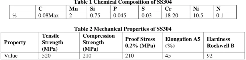
SS304 is nonmagnetic in nature. Type 304 stainless steel is an austenitic grade that can be severely deep drawn. This property has resulted in 304 being the dominant grade used in applications like sinks and saucepans. Type 304L is the low carbon version of 304.
Table 1 Chemical Composition of SS304
C Mn Si P S Cr Ni N
% 0.08Max 2 0.75 0.045 0.03 18-20 10.5 0.1
Table 2 Mechanical Properties of SS304
Property
Tensile Strength (MPa)
Compression Strength (MPa)
Proof Stress 0.2% (MPa)
Elongation A5 (%)
Hardness Rockwell B
Value 520 210 210 45 92
ii. Tool ISO 6L2525
Table 3. Specification of the Cutting Tool
Ordering
Code Tip
Dimensions
h b l1 f1 f2 ap rɛ ᵧ1 λ2
ISO 6L2525 1212
C10 12 12 140 35 15.5 20 1.2 120 00
35
iii. CNC Machine
“Fig 3 Mitutoyo Surftest SJ-210” “Fig 4 Ace Micromatic CNC Machine”
iv. Surface Finish Tester
Here Mitutoyo Surftest SJ-210 is used for measuring surface roughness of machined component.
B. MACHINING
A test piece of SS 304 material is clamped in three jaw chuck of CNC machine and initial rough cutting is done. Then 10 mm cut is taken for each speed, feed and depth of cut for parameters values in table 4.
(a) (b)
“Fig 5 Turning (a) Machining Operation (b) Machined Component”
C. MEASUREMENT OF SURFACE ROUGHNESS.
Mitutoyo Surftest was used to find surface roughness of machined component. Later by using equation 1.1 and 1.2 theoretical values of surface roughness are found out and is as shown in table 4.
Roughness (max) = 1000 x
r
f
8
2………..Eqn 1.1 [3].
Roughnessi = 1000 x
r
f
32
2……….Eqn 1.2 [3].
Ra = Average Surface Roughness in µm f = feed
r = nose radius
36 tool. This equation gives you a rough Ra value [3].
“Fig. 6 Surface Roughness values”
IV.RESULT AND CONCLUSIONS
TABLE 4.COMPARISON BETWEEN FINITE THEORETICAL AND EXPERIMENTAL RESULTS
Sr.
No.
Depth
(mm)
Feed
(mm/rev)
Speed
(rpm)
Max
Surface
Roughness
in µ
Average
Surface
Roughness
in µ
Theoretical
Max
Surface
Roughness
in µ
Theoretical
Average
Surface
Roughness
in µ
1
0.5
0.1
140
2.363
0.387
1.0417
0.2604
2
0.5
0.1
220
2.551
0.486
1.0417*
0.2604*
3
0.5
0.1
360
2.005
0.408
1.0417*
0.2604*
4
0.5
0.16
140
2.147
0.355
2.667
0.666
5
0.5
0.16
220
1.187
0.217
2.667*
0.666*
6
0.5
0.16
360
1.503
0.285
2.667*
0.666*
7
0.5
0.25
140
2.058
0.512
6.510
1.627
8
0.5
0.25
220
1.649
0.334
6.510*
1.627*
9
0.5
0.25
360
1.580
0.359
6.510*
1.627*
10
0.6
0.1
140
1.817
0.258
1.0417*
0.2604*
11
0.6
0.1
220
2.085
0.464
1.0417*
0.2604*
12
0.6
0.1
360
2.597
0.338
1.0417*
0.2604*
13
0.6
0.16
140
1.690
0.346
2.667*
0.666*
14
0.6
0.16
220
1.365
0.253
2.667*
0.666*
15
0.6
0.16
360
1.396
0.297
2.667*
0.666*
16
0.6
0.25
140
1.463
0.236
6.510*
1.627*
17
0.6
0.25
220
1.083
0.215
6.510*
1.627*
18
0.6
0.25
360
1.529
0.373
6.510*
1.627*
19
0.7
0.1
140
2.114
0.372
1.0417*
0.2604*
20
0.7
0.1
220
2.213
0.436
1.0417*
0.2604*
21
0.7
0.1
360
2.392
0.549
1.0417*
0.2604*
22
0.7
0.16
140
1.601
0.303
2.667*
0.666*
23
0.7
0.16
220
1.133
0.235
2.667*
0.666*
24
0.7
0.16
360
1.540
0.247
2.667*
0.666*
25
0.7
0.25
140
2.206
0.282
6.510*
1.627*
26
0.7
0.25
220
3.300
0.485
6.510*
1.627*
27
0.7
0.25
360
1.216
0.263
6.510*
1.627*
37
“Fig. 7 Effect of Speed and Feed on Surface Roughness, Keeping Depth of Cut Constant as 0.5mm.”
“Fig. 8 Effect of Speed and Feed on Surface Roughness, Keeping Depth of Cut Constant as 0.6 mm.”
“Fig. 9 Effect of Speed and Feed on Surface Roughness, Keeping Depth of Cut Constant as 0.7mm.”
“Fig. 10 Effect of Feed Variation on Surface Roughness (Theoretical).”
In this work behavior of vibration of the cutting tool was observed by changing cutting parameters i.e.; the speed, feed and the depth of cut. SS 304 was taken as the work piece material; the cutting tool was ISO 6L 2525. As there were 3 factors each having three levels so a total of 27 experiments were done by varying the factors and the data thus obtained is verified by using theoretical formulae’s.
It is observed that Surface roughness found with using theoretical equation shows that increase in feed rate increases both max and average surface roughness though experimental values of surface roughness shows significant variation at higher feed rates, it may be due to work-piece material hardness or poor machining condition such as dry turning operation.
REFERENCES
[1] M. Dogra,V. S. Sharmab, J. Dureja, “Effect of tool geometry variation on finish turning – A Review”, Journal of Engineering Science and Technology Review, 2011, pp. 1-2
[2] https://www.researchgate.net/figure/282365740_fig1_Figure-1-Factors-affecting-surface-roughness-during-SPIF [3] http://cadem.com/cncetc/cnc-turning-surface-finish-nose-radius/
[4] Zahari Taha, “Effect of Insert Geometry on Surface Roughness in the Turning Process of AISI D2”, 11th Asia Pacific Industrial Engineering and Management System Conference, 2010, pp. 2-3.