ORIGINAL ARTICLE
Modelling of the Influence of Tool Runout
on Surface Generation in Micro Milling
Wanqun Chen
1,2, Yazhou Sun
2, Dehong Huo
1*and Xiangyu Teng
1Abstract
Micro milling is a flexible and economical method to fabricate micro components with three-dimensional geometry features over a wide range of engineering materials. But the surface roughness and micro topography always limit the performance of the machined micro components. This paper presents a surface generation simulation in micro end milling considering both axial and radial tool runout. Firstly, a surface generation model is established based on the geometry of micro milling cutter. Secondly, the influence of the runout in axial and radial directions on the surface generation are investigated and the surface roughness prediction is realized. It is found that the axial runout has a significant influence on the surface topography generation. Furthermore, the influence of axial runout on the surface micro topography was studied quantitatively, and a critical axial runout is given for variable feed per tooth to generate specific surface topography. Finally, the proposed model is validated by means of experiments and a good correlation is obtained. The proposed surface generation model offers a basis for designing and optimizing surface parameters of functional machined surfaces.
Keywords: Surface generation, Roughness prediction, Surface topography, Runout, Micro milling
© The Author(s) 2019. This article is distributed under the terms of the Creative Commons Attribution 4.0 International License (http://creat iveco mmons .org/licen ses/by/4.0/), which permits unrestricted use, distribution, and reproduction in any medium, provided you give appropriate credit to the original author(s) and the source, provide a link to the Creative Commons license, and indicate if changes were made.
1 Introduction
Micro milling is recognized as one of the most versa-tile machining processes to fabricate micro components and micro features [1], due to the advantages including wide material choices, true 3D micro geometry machin-ing capability, high accuracy, low cost and environmen-tally friendliness [2–5]. Recently, micro milling has been employed to fabricate the microfluidic devices [6–10]. Microfluidic channels are the important part of micro-chemical devices, which is widely being used in microe-lectronic and biomedical applications. The characteristic scale of microfluidic channels is generally between a few to several hundred microns, and micro-milling has a very high superiority in such scale machining. Tool diam-eters are down-scaled in micro milling, unfortunately the surface roughness is not down-scaled in micro mill-ing, this is mainly due to the fact that cutting edge radius and machining dynamics such as tool runout are not
down-scaled and they are similar to those in conventional milling. Therefore, the relative surface roughness, i.e., the ratio of surface roughness to the machined feature size, is believed to be larger in micro milling. Research has shown that the wall roughness and micro topography can significantly affect the flow and drag along the microflu-idic channel path [11], and microreactors often need to control the flow pattern to achieve enhanced mixing, to achieve enhanced mass transfer, and improve the reac-tion rate. And on the other hand, design and control of wall roughness and micro topography has become an effective means of micro-flow control [12–14]. In addi-tion, the micro features size produced by micro milling makes the subsequent finishing processes, e.g., grinding or polishing, expensive or even impossible. Therefore, modelling surface generation in micro-milling is signifi-cant and it provides a theoretical basis the design and manufacture of micro-fluidic channels.
Research has been carried out in micro milling surface generation in recent years. Vogler et al. [15] developed a model to predict the surface generation for single-phase materials based on the minimum chip thickness con-cept. investigated the effect of micro tool cutting edge
Open Access
*Correspondence: [email protected]
1 Mechanical Engineering, School of Engineering, Newcastle University,
Newcastle upon Tyne NE1 7RU, UK
radius on the surface roughness in the micro machining, and pointed out that larger cutting edge radius would increase the surface roughness due to the existence of the minimum chip thickness. Oliaei and Karpat [16] inves-tigated the influence of machining parameters on the surface roughness of stainless steel machining. Bissacco et al. [17] studied the size effects on surface generation by ball nose and flat end micro milling of hardened tool steel, and the effects of the increased ratio between cut-ting edge radius and chip thickness have been observed. Sun et al. [18] studied the relationship among the sur-face roughness, the feed per tooth, as well as the cutter geometry. Li et al. [19] proposed a trajectory-based sur-face roughness model for micro-end-milling and proven capable of capturing the minimum chip thickness, micro tool geometry and process parameters. Based on this model, a surface roughness model with tool wear effect is developed by taking the material removal volume and cutting velocity into account and is experimentally vali-dated. Weule et al. [20] investigated surface generation in micro-end-milling of steel and concluded that the sur-face roughness had the increasing trend when the feed rate was smaller than the cutting edge radius. Previous research studied the influence of geometry of the cutter, machining parameters, tool wear and minimum cutting chip thickness on the surface generation in micro milling. While the runout of the tool is ignored, which plays an important role in the surface generation in micro mill-ing due to the fact that in micro millmill-ing the magnitude of tool runout is comparable with the feed per tooth. In this paper, a surface generation model is proposed consider-ing the tool runout both in axial and radial directions, after that the influence of the runout on the surface gen-eration is studied quantitatively.
2 Surface Generation Model in Micro Milling
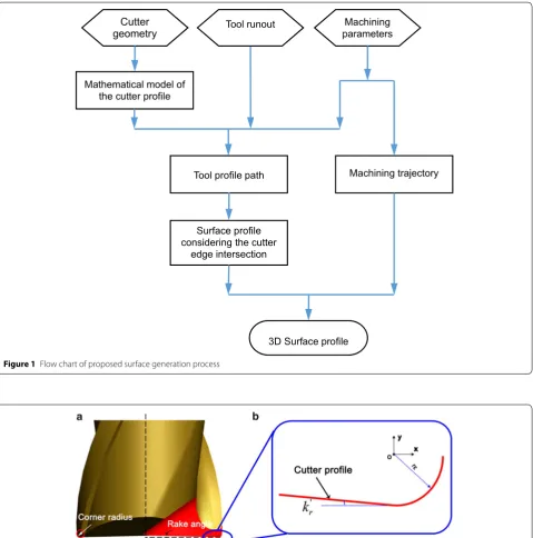
A model to simulate the surface generation in micro end milling is proposed by considering the tool-workpiece intersection caused by the runout of the cutter. The complex end milling cutter geometry is considered and used to generate the surface profile around the centerline region of the machined slot. For each tool path, the sur-face profile is computed as combination of the previously computed surface profile, the finial surface is generated by the deepest cutting path considering the tool inter-section. The following procedure is used in the model to develop the surface profile, as shown in Figure 1. Firstly, the cutter profile is described in a mathematical model, considering the geometry parameters of the cut-ter, including corner radius, end cutting edge angle; Sec-ondly, the cutter profile is translated according to the machining parameters, such as the feed per tooth and tool runout; Thirdly, the final surface profile is generated
by considering the intersection of the cutting edge. Lastly, the final surface profile is swept along the trajectory of the cutting path to form a three dimensional surface.
2.1 Mathematical Model of the Cutter and Ideal Machined Surface Generation
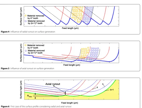
Figure 2 shows the contour of a micro milling tool, the cutter profile
x,y
can be expressed as:
where rε denotes the corner radius of the tool and kr′ denotes the rake angle.
The ideal surface roughness of the machined surface were mainly determined by the tool geometry (corner radius rε , rake angle k′
r ) and the feed per tooth fz , the sur-face left by the cutter can be divided into the following two cases.
1. rε>0 , fz≤2rεsinkr′ , the machined surface is made up of the circular arc edge of the tool, as shown in Figure 3(a). The maximum height of residual area (peak-valley) is
2. rε>0 , fz>2rεsinkr′ , the machined surface is made up of the circular arc edge of the tool and the end cutting edge, as shown in Figure 3(b). The maximum height of residual area (peak-valley) is
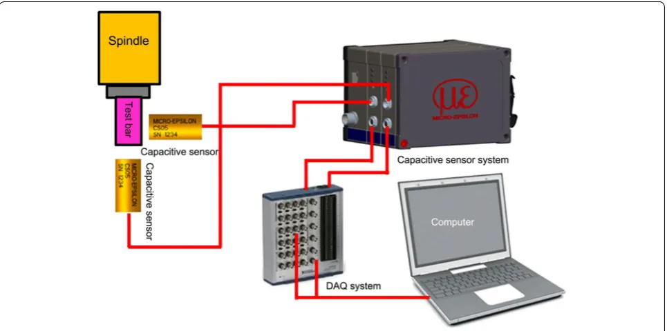
2.2 Surface Generation Model Considering Tool Runout When considering the tool runout, the machined surface generation becomes more complex, Figure 4 and Figure 5
show the influence of radial and axial runout on the sur-face generation.
From Figure 4 it can be found that the kth tooth removes more material than the (k+1)th, due to the runout in radial direction, which affect the uncut chip thickness of each feed per tooth. Thus, the runout in radial direction has a significant influence on cutting forces.
Figure 5 shows the influence of the runout in axial direction on surface generation. It can be found that the tool mark generates by the kth tooth was completely
(1)
y= r
2
ε−x2, rε≥x>−rεsin
k′
r
,
rεcos
k′
r
+x+rεsin k′ r tan k′ r
, x≤ −rεsin k′ r , (2)
RImax1=rε−
r2 ε− fz 2 2 ≈ f 2 z
8rε .
(3)
RImax2=rε
1−cosk′
r
+fzsinkr′
cosk′
r−sink
′
r
2rε
fzsinkr′
−1
removed by the (k+1)th tooth due to the cutter runout in axial direction. The finial profile of the machined sur-face formed by the (k+1)th tooth. The period of the tool mark is around twice time of the feed per tooth. Thus, the cutter runout in axial direction affects the cutting depth directly and hence has a significant influence on surface generation.
However, in a micro milling machining system, both radial and axial runout exist simultaneously, which make
the machined surface becomes more complex. When considering both radial and axial runout, the surface topography presents three typical cases.
1. rε>0 , fz≤2rεsinkr′ , the machined surface as shown in Figure 6 is made up of the circular arc edge of the tool, the maximum height of residual area (peak-val-ley) is
Cutter geometry
Mathematical model of the cutter profile
Machining parameters
Surface profile considering the cutter
edge intersection
Tool profile path Machining trajectory
3D Surface profile Tool runout
Figure 1 Flow chart of proposed surface generation process
Figure 3 Ideal machined surface in micro milling: a 1st case of the ideal machined surface, b 2nd case of the ideal machined surface
Figure 4 Influence of radial runout on surface generation
Figure 5 Influence of axial runout on surface generation
It can be found that in this case a slight axial runout ( raxial> f
2
z
2rε ) will cause the emergence of single-tooth cutting, which increases surface roughness signifi-cantly, i.e., almost 4 times larger than the ideal rough-ness as shown in Eq. (2). Considering that the magni-tude of inevitable axial runout is comparable to feed per tooth, in this case the ideal roughness as shown in Figure 3(a) is difficult to achieve. This explains the reason why in micro milling actual surface roughness deviates substantially from theoretical surface rough-ness in most of the machining system and merely reducing feedrate cannot improve surface roughness. 2. rε>0 , fz>2rεsinkr′ , the machined surface as shown
in Figure 7 is made up of the circular arc edge of the tool and the end cutting edge. The second and third cases fall into this criterion and are illustrated as fol-lows.
In the second case, the surface is composed by the two teeth, and the maximum roughness of the sur-face is
(4)
RAmax=rε−
r2 ε − 2fz 2 2 ≈ f 2 z 2rε
.
(5)
RAmax1=rε
1−cosk′
r
+fzsinkr′
×
cosk′ r−sinkr′
2rε
fzsinkr′
−1
+2raxial.
It can be found that the RAmax1 is equal to the ideal
RImax2 as shown in Eq. (3) plus the axial runout of the cutter.
In the third case, the surface is only formed by one tooth as shown in Figure 8, and the maximum rough-ness of the surface (peak-valley) is
In this case, it can be found that the tool path on the machined surface is equal to the spindle rotation speed, rather than the spindle rotation speed multiplies the number of flutes.
The critical axial runout for the separation of the sec-ond case and the third case surface generation can be judged as follows:
when raxial≤(RAmax2−RImax2)/2 , the second case occur;
when raxial> (RAmax2−RImax2)/2, the third case occur.
A critical axial runout diagram for the separation of the second case and the third case surface generation is given in Figure 9, for a specified feed per tooth, if the actual axial runout is smaller than the critical axial runout, then the second case of the surface profile will occur. Otherwise if the real axial runout is larger than the critical axial runout, then the third case of the sur-face profile will occur.
(6)
RAmax2=rε
1−cosk′ r
+2fzsinkr′
cosk′ r−sink
′ r
2rε
2fzsinkr′
−1
.
Figure 7 Second case of the surface profile considering radial and axial runout
3 Experimental Validation
3.1 Determination of Tool Runout
The experiments were carried out on a 3-axis micro mill-ing machine tool (Nanowave MTS5R), the runout of the high speed spindle is tested by using a modular capacitive sensor system (Demodulator DL6220, Micro-epsilon), two capacitive sensors (CS005) with 1 nm resolution and 50 μm measuring range. As shown in Figure 10, an
ultra-precision test bar was clamped in the spindle, and two capacitive sensors were used to test the spindle runout with 20000 r/min in axial direction and radial direction. The test results show that the axial and radial runout is 1 μm and 1.6 μm, respectively.
From the judgment map as Figure 9, it can be found that for axial runout of 1 μm, when the feed per tooth less than 24 μm per tooth, the machined surface genera-tion falls into the third case; and when the feed per tooth larger than 24 μm per tooth, the machined surface gen-eration falls into the second case.
3.2 Simulation and Experimental Verification
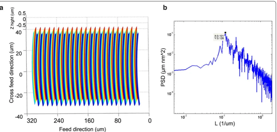
Two set simulation and machining experiments are car-ried out with a 2 flutes micro milling cutter, the cutter diameter is 0.5 mm, the corner radius and the end cutting edge angle are measured as 5 μm and 5°, respectively. The machining parameters used in the experiments are 5 μm per tooth and 35 μm per tooth, respectively, at a spindle speed of 20000 r/min and an axial depth of cut of 20 μm.
Figure 11(a) shows the surface topography simulation results of 5 μm feed per tooth. The simulation results are analyzed by PSD as shown in Figure 11(b). The period of the tool marks is determined as 0.101 μm−1 (10 μm), which indicates that the tool marks of the 2nd tooth are removed by the 1st tooth because of the influence of the axial runout. Therefore, the tool make period is twice of the feed per tooth.
Figure 9 Critical axial runout for the separation of the second case and the third case surface generation
Figure 12(a) shows the surface topography simula-tion results of 35 μm feed per tooth. The PSD analysis of the simulation results as shown in Figure 12(b) indi-cates that the period of the tool marks is determined as 0.0287 μm−1 (35 μm), which indicates that with the increase of the feed per tooth, the effect of axial runout on the topography can be reduced. Each cutting tooth can be reflected in the final surface topography, there-fore, the tool marks period agree with the feed per tooth.
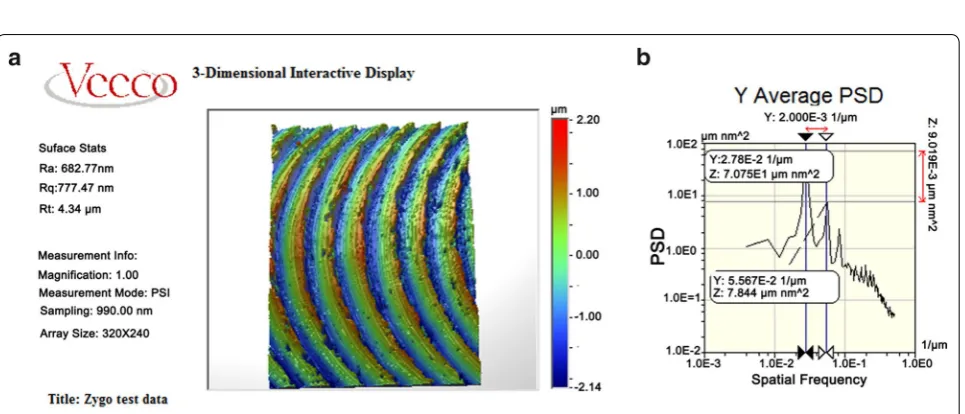
The machining experiments were carried out using the same machining parameters as those in the simulation. Figures 13 and 14 give the surface measurement results, which were obtained by a white light interferometer (Vecco NTll00). It can be seen that when the feed per tooth is 5 μm, the period of the tool mark is twice time of the feed per tooth 0.103 μm−1 (9.7 μm). When the feed per tooth increases to 35 μm, the period of the tool mark is the same as the feed per tooth 0.0278 μm−1 (35.9 μm). The experiment results agree well with the simulation Figure 11 Surface topography simulation results of 5 μm feed per tooth: a surface topography, b PSD analysis
results and hence verify the reliability of the proposed method.
4 Conclusions
In this paper, a surface generation model of micro end milling has been developed by taking into account tool runout in the machining process. A numerical model based on the geometry of the cutter profile is estab-lished to investigate the tool intersection caused by the tool runout. The influence of the tool runout on machined surface roughness and machined topography
are discussed. Simulation using the proposed model with different feed per tooth (5 μm/tooth, 35 μm/tooth) and the results were verified by corresponding micro milling experiments. The following conclusions can be drawn:
• Tool runout has a significant influence of the sur-face roughness, and axial tool runout limits the achievable surface roughness. Three typical surface topography generation cases of the machined sur-face in micro milling are presented by considering tool runout, and the emergence conditions for each Figure 13 Machined surface topography results of 5 μm feed per tooth: a surface topography, b PSD analysis
surface generation cases are investigated quantita-tively.
• The tool runout in axial direction has significant influence on the machined topography generation. • Proposed surface generation model has been verified
by the micro milling experiments over a wide range of feedrate, and the results show that it provides accurate surface topography prediction.
Authors’ Contributions
DH and WC were in charge of the whole trial; WC wrote the manuscript; YS and XT assisted with sampling and laboratory analyses. All authors read and approved the final manuscript.
Author Details
1 Mechanical Engineering, School of Engineering, Newcastle University,
Newcastle upon Tyne NE1 7RU, UK. 2 Center for Precision Engineering, Harbin
Institute of Technology, Harbin 150001, China.
Authors’ Information
Wanqun Chen, born in 1987, is currently an associate professor at School of Mechatronics Engineering, Harbin Institute of Technology, China. He is also a Research Associate at School of Mechanical and Systems Engineering, Newcastle University, UK. He received his PhD degree from Harbin Institute of Technology, China, in 2014. His research interests include ultra-precision machine design and dynamic analysis.
Yazhou Sun, born in 1968, is currently a professor at School of Mechatronics Engineering, Harbin Institute of Technology, China. He received his PhD degree from Harbin Institute of Technology, China, in 2005. His research interests include ultra-precision machine design and dynamic analysis.
Dehong Huo, born in 1975, is currently a Senior Lecturer at School of Mechanical and Systems Engineering, Newcastle University, UK. He received his PhD degree from Harbin Institute of Technology, China, in 2004. His research interests include micro machining process and precision machine design.
Xiangyu Teng, born in 1991, is currently a PhD candidate at School of Mechanical and Systems Engineering, Newcastle University, UK.
Competing Interests
The authors declare that they have no competing interests.
Funding
Supported by Engineering and Physical Sciences Research Council (Grant No. EP/M020657/1), National Natural Science Foundation of China (Grant No. 51505107) and Project of Natural Scientific Research Innovation Foundation in Harbin Institute of Technology (Grant No. HIT.NSRIF.2017029).
Publisher’s Note
Springer Nature remains neutral with regard to jurisdictional claims in pub-lished maps and institutional affiliations.
Received: 8 February 2017 Accepted: 10 January 2019
References
[1] K Cheng, D Huo. Micro cutting: fundamentals and applications. Wiley, Chichester, 2013.
[2] X Liu, R DeVor, S Kapoor, et al. The mechanics of machining at the microscale: Assessment of the current state of the science. Journal of Manufacturing Science & Engineering, 2004, 126: 666-678.
[3] S Bruschi, et al. Environmentally clean micromilling of electron beam melted Ti6Al4V. Journal of Cleaner Production, 2016(133): 932-941. [4] Wei Li, Zhixiong Zhou, Bi Zhang, et al. A micro-coupling for micro
mechanical systems. Chinese Journal of Mechanical Engineering, 2016, 29(3): 571-578.
[5] Xuefeng Wu, Gaocheng Feng, Xianli Liu. Design and implementation of a system for laser assisted milling of advanced materials. Chinese Journal of Mechanical Engineering, 2016, 29(5): 921-929.
[6] David J Guckenberger, et al. Micromilling: a method for ultra-rapid prototyping of plastic microfluidic devices. Lab on a Chip, 2015, 15(11): 2364-2378.
[7] H Andersson, A Van. Microfluidic devices for cellomics: a review. Sensors and Actuators B: Chemical, 2003, 92(3): 315-325.
[8] I Ogilvie, V Sieben, C Floquet, et al. Reduction of surface roughness for optical quality microfluidic devices in PMMA and COC. Journal of Micro-mechanics and Microengineering, 2010, 20(6): 065016.
[9] H Becker, L E Locascio. Polymer microfluidic devices. Talanta, 2002, 56(2): 267-287.
10] A Sodemann, M Li, R Mayor, et al. Micromilling of molds for microfluidic blood diagnostic devices. Proc. Annu. Meet Am. Soc. Precis. Eng., 2009: 4-9. [11] C Mishra, Y Peles. Cavitation in flow through a micro-orifice inside a
silicon microchannel. Physics of Fluids, 2005, 17(1): 013601.
[12] C Kleinstreuer, J Koo. Computational analysis of wall roughness effects for liquid flow in micro-conduits. Journal of Fluids Engineering, 2004, 126(1): 1-9. [13] R Lopes, R O Rodrigues, D Pinho, et al. Low cost microfluidic device for
partial cell separation: micromilling approach. Industrial Technology (ICIT), 2015 IEEE International Conference on. IEEE, 2015: 3347-3350.
[14] M Ali. Fabrication of microfluidic channel using micro end milling and micro electrical discharge milling. International Journal of Mechanical and Materials Engineering, 2009, 4(1): 93-97.
[15] V M ogler, R DeVor, S Kapoor. On the modeling and analysis of machining performance in micro-endmilling, Part I: Surface generation. Journal of Manufacturing Science and Engineering, 2004, 126(4): 685-694.
[16] S Oliaei, Y Karpat. Experimental investigations on micro milling of Stavax stainless steel. Procedia CIRP, 2014, 14: 377-382.
[17] G Bissacco, H N Hansen, L De Chiffre. Size effects on surface generation in micro milling of hardened tool steel. CIRP Annals-Manufacturing Technol-ogy, 2006, 55: 593-596.
[18] Y Sun, Y Liang, R Du. Simulation and analysis of surface generation in micro-milling. Proceedings of the 6th WSEAS International Conference on Robotics, Control and Manufacturing Technology, Hangzhou, China, 2006: 30-35.
[19] H Li, X Lai, C Li, et al. Modelling and experimental analysis of the effects of tool wear, minimum chip thickness and micro tool geometry on the surface roughness in micro-end-milling. Journal of Micromechanics and Microengineering, 2007, 18(2): 025006.